Download to read offline
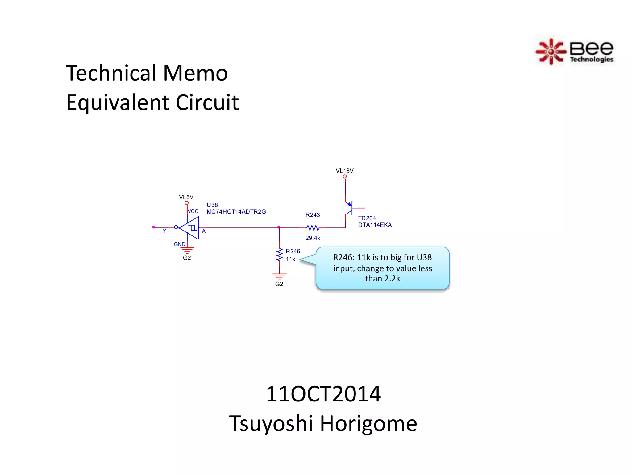
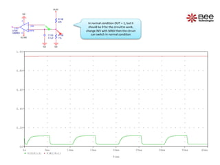

This technical memo discusses changes needed to an electronic circuit diagram. The memo notes that the value of resistor R246, which is connected to the input of chip U38, is too large and should be changed to a value less than 2.2k. It also states that the inverting symbol on chip U100 should be changed to a non-inverting symbol in order for the circuit to switch in normal conditions as the output is currently 1 but needs to be 0. Simulation waveforms are included showing the voltage levels over time at nodes U101:1 and R139:1.