
More Related Content
What's hot
What's hot (20)
Similar to EG UNIT 1PLANE CURVES.ppt
Similar to EG UNIT 1PLANE CURVES.ppt (20)
Recently uploaded
Recently uploaded (20)
EG UNIT 1PLANE CURVES.ppt
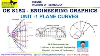
- 1. GE 8152 - ENGINEERING GRAPHICS Dr.R.Ganesamoorthy. Professor / Mechanical Engineering. Chennai Institute of Technology. GE8152- ENGINEERING GRAPHICS - UNIT-1 PLANE CURVES UNIT -1 PLANE CURVES
- 2. CONIC SECTIONS GE8152- ENGINEERING GRAPHICS - UNIT-1 PLANE CURVES Definition: The sections obtained by the intersection of a right circular cone by a cutting plane in different positions are called conic sections or conics.
- 3. CONIC SECTIONS GE8152- ENGINEERING GRAPHICS - UNIT-1 PLANE CURVES CIRCLE: When the cutting plane is parallel to the base or perpendicular to the axis, then the true shape of the section is circle. ELLIPSE: When the cutting plane is inclined to the horizontal plane and perpendicular to the vertical plane, then the true shape of the section is an ellipse.
- 4. GE8152- ENGINEERING GRAPHICS - UNIT-1 PLANE CURVES Parabola: When the cutting plane is inclined to the axis and is parallel to one of the generators, then the true shape of the section is a parabola. Hyperbola: When the cutting plane is parallel to the axis of the cone, then the true shape of the section is a rectangular hyperbola.
- 5. GE8152- ENGINEERING GRAPHICS - UNIT-1 PLANE CURVES Focus & Directrix Conic may be defined as the locus of a point moving in a plane in such a way that the ratio of its distances from a fixed point, called focus and a fixed straight line called directrix. Eccentricity The ratio of shortest distance from the focus to the shortest distance from the directrix is called eccentricity.
- 6. GE8152- ENGINEERING GRAPHICS - UNIT-1 PLANE CURVES
- 7. GE8152- ENGINEERING GRAPHICS - UNIT-1 PLANE CURVES 1.Draw the directrix AB and axis CC’ 2.Mark F on CC’ such that CF = 80 mm. 3.Divide CF into 7 equal parts and mark V at the fourth division from C. 4.Now, e = FV/ CV = 3/4. 5.At V, erect a perpendicular VB = VF. Join CB. Through F, draw a line at 45° to meet CB produced at D. Through D, drop a perpendicular DV’on CC’. Mark O at the midpoint of V– V’. Draw an ellipse when the distance between the focus and directrix is 80mm and eccentricity is ¾.
- 8. GE8152- ENGINEERING GRAPHICS - UNIT-1 PLANE CURVES 6.With F as a centre and radius = 1–1’, cut two arcs on the perpendicular through 1 to locate P1 and P1’. Similarly, with F as centre and radii =2-2’, 3–3’, etc., cut arcs on the corresponding perpendiculars to locate P2 and P2’, P3 and P3’, etc. Also, cut similar arcs on the perpendicular through O to locate V1 and V1’. 7. Draw a smooth closed curve passing through V, P1, P/2, P/3,., V1, …,V’, …, V1’, … P/3’, P/2’, P1’. 8. Mark F’ on CC’ such that V’ F’ = VF.
- 9. GE8152- ENGINEERING GRAPHICS - UNIT-1 PLANE CURVES Draw an ellipse when the distance between the focus and directrix is 50mm and eccentricity is 2/3. Also draw the tangent and normal curve.
- 10. GE8152- ENGINEERING GRAPHICS - UNIT-1 PLANE CURVES Construction of Parabola:
- 11. GE8152- ENGINEERING GRAPHICS - UNIT-1 PLANE CURVES Construct a parabola when the distance of the Focus from the directrix is 60 mm. Note: Eccentricity, e = 1. 1.Draw directrix AB and axis CC’ as shown. 2.Mark F on CC’ such that CF = 60 mm. 3.Mark V at the midpoint of CF. Therefore, e = VF/ VC = 1. At V, erect a perpendicular VB = VF. Join CB. 4.Mark a few points, say, 1, 2, 3, … on VC’ and erect perpendiculars through them meeting CB produced at 1’,2’, 3’… 5.With F as a centre and radius = 1–1’, cut two arcs on the perpendicular through 1 to locate P1 and P1’. Similarly, with F as a centre and radii = 2–2’, 3–3’, etc., cut arcs on the corresponding perpendiculars to locate P2 and P2’,P3 and P3’ etc. 6.Draw a smooth curve passing through V, P1,P2,P3 …P3’,P2’,P1’.
- 12. GE8152- ENGINEERING GRAPHICS - UNIT-1 PLANE CURVES Construct a parabola when the distance of the Focus from the directrix is 50 mm. Also draw tangent and normal curve at any point.
- 13. GE8152- ENGINEERING GRAPHICS - UNIT-1 PLANE CURVES Construction of Hyperbola: Hyperbolic shapes finds large number of industrial applications like the shape of cooling towers, mirrors Used for long distance telescopes, etc.
- 14. GE8152- ENGINEERING GRAPHICS - UNIT-1 PLANE CURVES Draw a hyperbola when the distance of the focus from the directrix is 55 mm and eccentricity is 3/2. 1. Draw a perpendicular line AB (directrix) and a horizontal line CC’ (axis). 2. Mark the focus point F on the axis line 55 mm from the directrix. 3. Divide the CF in to 5 equal parts. 4. As per the eccentricity mark the vertex V, in the third division of CF 5. Draw a perpendicular line from vertex V, and mark the point B, 6. with the distance VF. 7. Join the points C& B and extend the line.
- 15. GE8152- ENGINEERING GRAPHICS - UNIT-1 PLANE CURVES 7. Draw number of smooth vertical lines 1,2,3,4,5,6,etc., as shown in figure. 8. Now mark the points 1′, 2′, 3′, 4′, 5′… 9. Take the vertical distance of 11′ and with F as centre draw an arc cutting the vertical line 11′ above and below the axis. 10. Similarly draw the arcs in all the vertical lines (22′, 33′, 44′…) 11. Draw a smooth curve through the cutting points to get the required hyperbola by free hand.
- 16. GE8152- ENGINEERING GRAPHICS - UNIT-1 PLANE CURVES Draw a hyperbola when the distance of the focus from the directrix is 50 mm and eccentricity is 3/2. Also draw tangent and normal curve at any point.
- 17. GE8152- ENGINEERING GRAPHICS - UNIT-1 PLANE CURVES Cycloidal curves Cycloidal curves are generated by a fixed point on the circumference of a circle, which rolls without slipping along a fixed straight line or a circle. In engineering drawing some special Curves ( Cycloidal curves) are used in the profile of teeth of gear wheels. The rolling circle is called generating circle. The fixed straight line or circle is called directing line or directing circle.
- 18. GE8152- ENGINEERING GRAPHICS - UNIT-1 PLANE CURVES 1. Cycloid is a curve generated by a point on the circumference of a circle which rolls along a straight line. 2. Draw a circle with diameter 50mm and mark the centre O. 3. Divide the circle in to 12 equal parts as1,2,3…12. 4. Draw horizontal line from the bottom points of the circle, with the distance equal to the circumference of the circle (ПD) and mark the other end point B. 5. Divide the line AB in to 12 equal parts. (1′, 2′, 3′…12′) 6. Draw a horizontal line from O to and mark the equal distance point O1, O2,O3…O12. 7. Draw smooth horizontal lines from the points 1,2,3…12.
- 19. GE8152- ENGINEERING GRAPHICS - UNIT-1 PLANE CURVES 8. When the circle starts rolling towards right hand side, the point 1 coincides with 1′ at the same time the centreO moves to O1. Take OA as radius, O1 as center draw an arc to cut the horizontal line 1 to mark the point a1. 9. Similarly O2 as center and with same radius OA draw an arc to cut the horizontal line 2 to mark the point a2. Similarly mark a3, a4…a11. 10. Draw a smooth curve through the points a1, a2, a3,…. a11, B by free hand. 11. The obtained curve is a cycloid
- 20. GE8152- ENGINEERING GRAPHICS - UNIT-1 PLANE CURVES A circle of 72mm dia rolls along a straight line without slipping. Draw the curve traced out by a point P on the circumference, for complete one revolution. Name the curve, also draw the tangent and normal curve at a point 62 mm from the straight line.
- 21. GE8152- ENGINEERING GRAPHICS - UNIT-1 PLANE CURVES Epicycloid is the curve generated by a point on the circumference of a circle which rolls without slipping along another circle outside it.
- 22. GE8152- ENGINEERING GRAPHICS - UNIT-1 PLANE CURVES 1. With O as centre and radius OP (base circle radius), draw an arc PQ. 2. The included angle θ = (r/R) x 360°. 3. With O as centre and OC as radius, draw an arc to represent locus of centre. 4. Divide arc PQ in to 12 equal parts and name them as 1’, 2’, …., 12’. 5. Join O1’, O2’, … and produce them to cut the locus of centres at C1, C2, ….C12. Taking C1 as centre, 6. and radius equal to r, draw an arc cutting the arc through 1 at P1. 7. Taking C2 as centre and with the same radius, draw an arc cutting the arc through 2 at P2 Similarly obtain points P3, P3, …., P12. 8. Draw a smooth curve passing through P1, P2….. , P12, which is the required epiclycloid.
- 23. GE8152- ENGINEERING GRAPHICS - UNIT-1 PLANE CURVES
- 24. GE8152- ENGINEERING GRAPHICS - UNIT-1 PLANE CURVES Construct a epi-cycloid rolling circle 60mm diameter and directing circle 122mm radius. Draw also the tangent and normal at M, which on the curve. 1. With O as centre and radius OP (base circle radius), draw an arc PQ. 2. The included angle θ = (r/R) x 360°. 3. With O as centre and OC as radius, draw an arc to represent locus of centre. 4. Divide arc PQ in to 12 equal parts and name them as 1’, 2’, …., 12’. 5. Join O1’, O2’, … and produce them to cut the locus of centres at C1, C2, ….C12. Taking C1 as centre, 6. and radius equal to r, draw an arc cutting the arc through 1 at P1. 7. Taking C2 as centre and with the same radius, draw an arc cutting the arc through 2 at P2 Similarly obtain points P3, P3, …., P12. 8. Draw a smooth curve passing through P1, P2….. , P12, which is the required epiclycloid.
- 25. GE8152- ENGINEERING GRAPHICS - UNIT-1 PLANE CURVES Hypocycloid is the curve generated by a point on the circumference of a circle which rolls without slipping inside another circle.
- 26. GE8152- ENGINEERING GRAPHICS - UNIT-1 PLANE CURVES 1.With O as centre and radius OB (base circle radius), draw an arc BA. 2.The included angle θ = (r/R) x 360°. With O as centre and OB as radius, draw an arc to represent locus of centre. 3.Divide arc AB in to 12 equal parts and name them as 1’, 2’, …., 12’. Join O1’, O2’, …, O12’ so as to cut the locus of centres at C1, C2,….C12. 4.Taking C1 as centre, and radius equal to r, draw an arc cutting the arc through 1 at P1. Taking C2 as centre and with the same radius, draw an arc cutting the arc through 2 at P2. 5.Similarly obtain points P3, P3, …., P12. 6.Draw a smooth curve passing through P1, P2….. , P12, which is the required hypocycloid.
- 27. GE8152- ENGINEERING GRAPHICS - UNIT-1 PLANE CURVES
- 28. GE8152- ENGINEERING GRAPHICS - UNIT-1 PLANE CURVES INVOLUTES: An involutes is a curve traced by a point on a perfectly flexible string, while unwinding from around a circle or polygon the string being kept taut (tight). It is also a curve traced by a point on a straight line while the line is rolling around a circle or polygon without slipping.
- 29. GE8152- ENGINEERING GRAPHICS - UNIT-1 PLANE CURVES Draw an involutes of a given square. 1. Draw the given square ABCD of side a.(a=30mm) 2. Taking D as the starting point, with centre A and radius DA=a, draw an arc to intersect the line BA produced at P1. 3. With Centre B and radius BP1 = 2 a, draw on arc to intersect the line CB produced at P2. 4. Similarly, locate the points P3 and P4. 5. The curve through D, PI' P2, P3 and P4 is the required involutes. 6. DP 4 is equal to the perimeter of the square.
- 30. GE8152- ENGINEERING GRAPHICS - UNIT-1 PLANE CURVES Construction of Involutes of circle 1. Draw the circle with O as centre and OA as radius.(20mm). 2. Draw line P-P12 = 2π D, tangent to the circle at P 3. Divide the circle into 12 equal parts. Number them as1, 2… 4. Divide the line PQ into 12 equal parts and number as1΄,2΄….. 5. Draw tangents to the circle at 1, 2,3…. 6. Locate points P1, P2 such that 1-P1 = P1΄, 2-P2 = P2΄ Join P, P1,P2... 7.The tangent to the circle at any point on it is always normal to the its involutes.
- 31. GE8152- ENGINEERING GRAPHICS - UNIT-1 PLANE CURVES Thank you