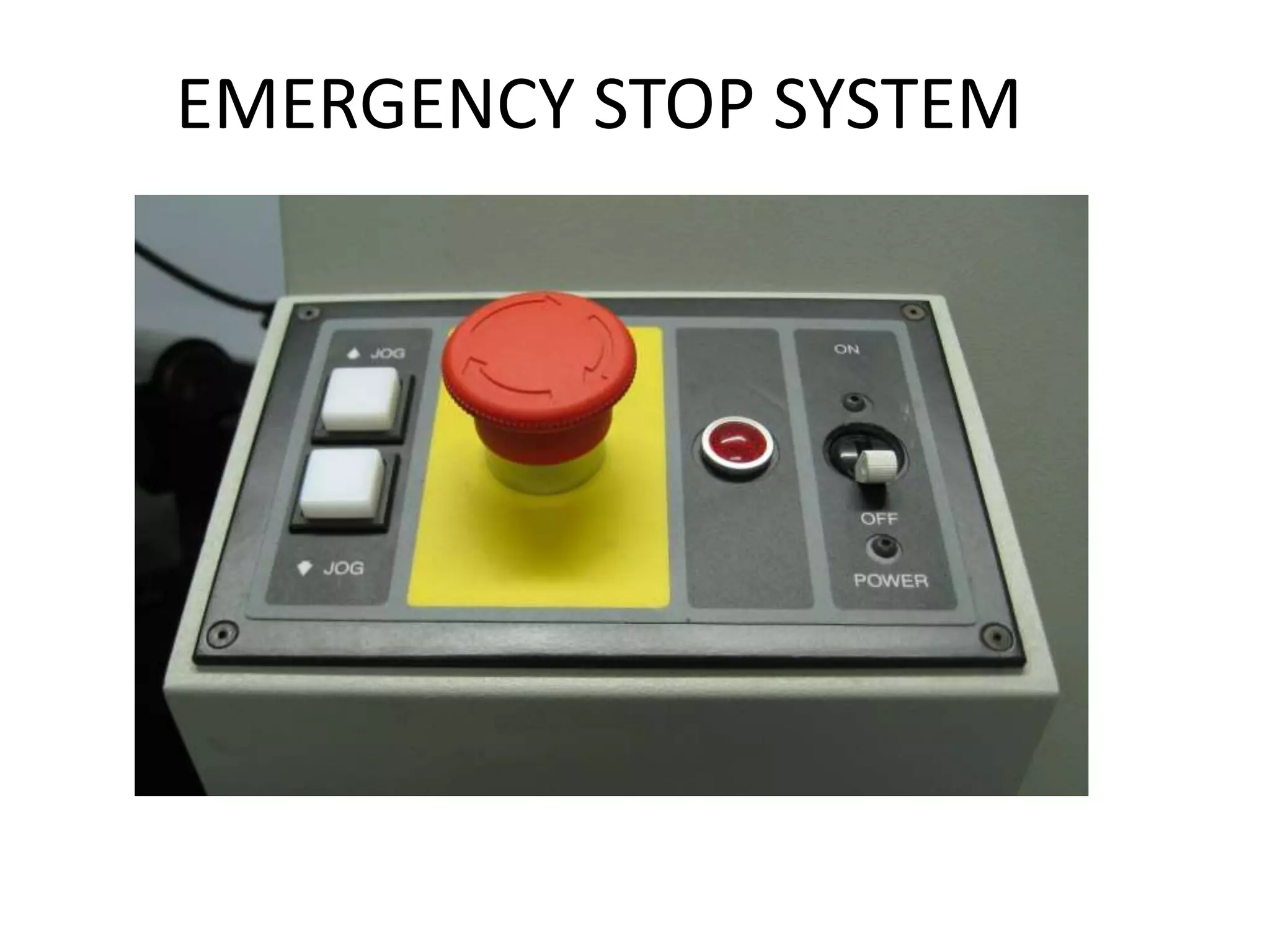
EMERGENCY STOP SYSTEM
DEFINITION
An emergency stop function is intended:
• to avert arising or to reduce existing hazards to
persons, damage to machinery or to work in
progress;
• to be initiated by a single human action when
the normal stopping function is inadequate for
this purpose.
• normal shut-down switch shuts down all systems in an
orderly fashion and turns the machine off without
damaging it.
• But an emergency stop switch is designed and configured
to completely and as quickly as possible abort the
operation, even if this damages equipment and be
operable in a manner that is quick, simple & be obvious
even to an untrained operator or a bystander.
• Many kill switches feature a removable barrier or other
protection against accidental activation (e.g., a plastic cover
that must be lifted or glass that must be broken).
Location
• They should be positioned for easy access by the operator or
anyone who
may need to use them, however, they should not be located where
their use could endanger the user.
Remember that the person using the emergency stop may not
necessarily be the person in danger! It may, therefore, be prudent to
position an emergency stop near an adjacent machine, or machine
zone in the case of a complex system, giving the neighbouring operator
the opportunity to stop the machine if the operator gets into trouble.
Where this is done, the zone of effectiveness of the Emergency Stop
must be clearly indicated to avoid confusion.
TYPES by BS EN 418
• Stop category 0:-
• Uncontrolled stop -- stopping by immediate removal of power to
the machine
• actuator(s), all brakes and/or mechanical stopping devices being
applied.
•
• Stop category 1:-
• Controlled stop -- with power available to the machine actuator(s)
to achieve
• the stop and then removal of the power when the stop is achieved.
•
• Stop category 2:-
• Controlled stop -- with power left available to the machine
actuator(s).
DNV-OS-D201
ELECTRICAL INSTALLATIONS
APRIL 2011
—no single failure will cause loss of duplicated essential or important equipment.
— The control circuits for emergency stop of duplicated equipment shall be arranged as two
separate circuits with separate cables. A common stop button with several contacts (separate for
each consumer) will be accepted.
— The emergency stop signal shall act independently of any software based control system for
the same consumer.
— A computer based emergency stop systems shall be independent from other computer based
systems with control functions for the same consumers. It shall have facilities to detect failures
that will set the system inoperable, and give alarm to the main alarm system. See DNV-OS-D202.
— Alarm for loss of power shall be provided for normally open emergency stop circuits.
DNV GUIDANCE
Emergency stop systems may be based on both
normally open (NO) and normally closed (NC)
circuits.
Systems, which can be stopped without any hazard,
should be based on NC circuits,
emergency stop of systems having effect on
propulsion motors and thruster should
be based on NO circuits.
DNV
• — fuel oil transfer pumps
• — fuel oil feed and booster pumps
• — nozzles cooling pumps when fuel oil is used as coolant
• — fuel and lubrication oil purifiers
• — pumps for oil-burning installations
• — fans for forced draught to boilers
• — all ventilation fans
• — all electrical driven lubrication oil pumps
• — thermal oil circulating pumps
• — hydraulic oil pumps in machinery space.
CARGO PUMPS
• BRIDGE CONSOLE AFT
• CARGO CABINET MAIN DECK
• when we press the emergency stop button, the corresponding
breaker for the circuit at cargo switch board will be tripped, hence
the pump stops. . for restarting the pump we have to reset the
emergency stop button that we pressed.
• usually there will be 2 independent pumps each can be controlled
separately.
• but emergency stop is common for both pumps ,
CO2 SYSTEM
• It is a system used to protect the main engine room
from fire .
• At the occurrence of fire CO2 will be released manually
.
• But we know that
 increased concentration of CO2 in inhaling air can
cause coma and death for persons inside engine room.
 engine room should be isolated from nearby
compartments and from ventilation ducts .
 warning should be given to the crew at the spot to
evacuate immediately.
PUSH BUTTON
SEALING
FRONT PLATE
FIXING NUT
SWITCHING ELEMENT
EMERGENCY STOP SYSTEM

EMERGENCY STOP SYSTEM

  • 1.
  • 3.
    DEFINITION An emergency stopfunction is intended: • to avert arising or to reduce existing hazards to persons, damage to machinery or to work in progress; • to be initiated by a single human action when the normal stopping function is inadequate for this purpose.
  • 4.
    • normal shut-downswitch shuts down all systems in an orderly fashion and turns the machine off without damaging it. • But an emergency stop switch is designed and configured to completely and as quickly as possible abort the operation, even if this damages equipment and be operable in a manner that is quick, simple & be obvious even to an untrained operator or a bystander. • Many kill switches feature a removable barrier or other protection against accidental activation (e.g., a plastic cover that must be lifted or glass that must be broken).
  • 5.
    Location • They shouldbe positioned for easy access by the operator or anyone who may need to use them, however, they should not be located where their use could endanger the user. Remember that the person using the emergency stop may not necessarily be the person in danger! It may, therefore, be prudent to position an emergency stop near an adjacent machine, or machine zone in the case of a complex system, giving the neighbouring operator the opportunity to stop the machine if the operator gets into trouble. Where this is done, the zone of effectiveness of the Emergency Stop must be clearly indicated to avoid confusion.
  • 6.
    TYPES by BSEN 418 • Stop category 0:- • Uncontrolled stop -- stopping by immediate removal of power to the machine • actuator(s), all brakes and/or mechanical stopping devices being applied. • • Stop category 1:- • Controlled stop -- with power available to the machine actuator(s) to achieve • the stop and then removal of the power when the stop is achieved. • • Stop category 2:- • Controlled stop -- with power left available to the machine actuator(s).
  • 7.
    DNV-OS-D201 ELECTRICAL INSTALLATIONS APRIL 2011 —nosingle failure will cause loss of duplicated essential or important equipment. — The control circuits for emergency stop of duplicated equipment shall be arranged as two separate circuits with separate cables. A common stop button with several contacts (separate for each consumer) will be accepted. — The emergency stop signal shall act independently of any software based control system for the same consumer. — A computer based emergency stop systems shall be independent from other computer based systems with control functions for the same consumers. It shall have facilities to detect failures that will set the system inoperable, and give alarm to the main alarm system. See DNV-OS-D202. — Alarm for loss of power shall be provided for normally open emergency stop circuits.
  • 8.
    DNV GUIDANCE Emergency stopsystems may be based on both normally open (NO) and normally closed (NC) circuits. Systems, which can be stopped without any hazard, should be based on NC circuits, emergency stop of systems having effect on propulsion motors and thruster should be based on NO circuits.
  • 9.
    DNV • — fueloil transfer pumps • — fuel oil feed and booster pumps • — nozzles cooling pumps when fuel oil is used as coolant • — fuel and lubrication oil purifiers • — pumps for oil-burning installations • — fans for forced draught to boilers • — all ventilation fans • — all electrical driven lubrication oil pumps • — thermal oil circulating pumps • — hydraulic oil pumps in machinery space.
  • 10.
    CARGO PUMPS • BRIDGECONSOLE AFT • CARGO CABINET MAIN DECK • when we press the emergency stop button, the corresponding breaker for the circuit at cargo switch board will be tripped, hence the pump stops. . for restarting the pump we have to reset the emergency stop button that we pressed. • usually there will be 2 independent pumps each can be controlled separately. • but emergency stop is common for both pumps ,
  • 11.
    CO2 SYSTEM • Itis a system used to protect the main engine room from fire . • At the occurrence of fire CO2 will be released manually . • But we know that  increased concentration of CO2 in inhaling air can cause coma and death for persons inside engine room.  engine room should be isolated from nearby compartments and from ventilation ducts .  warning should be given to the crew at the spot to evacuate immediately.
  • 12.