Download to read offline
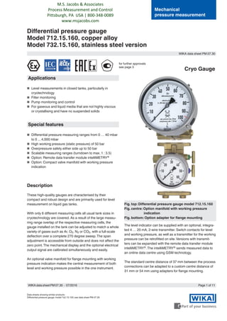


The document details the specifications and functionalities of two models of differential pressure gauges (712.15.160 in copper alloy and 732.15.160 in stainless steel) designed for level and pressure measurement in various applications, particularly in cryotechnology. These gauges feature a wide measuring range, high working pressure, options for remote data transfer, and additional customization such as scale designs and integrated transmitters. It also describes their design principles, operating ranges, compliance with various certifications, and optional accessories for enhanced functionality.


