Downloaded 92 times


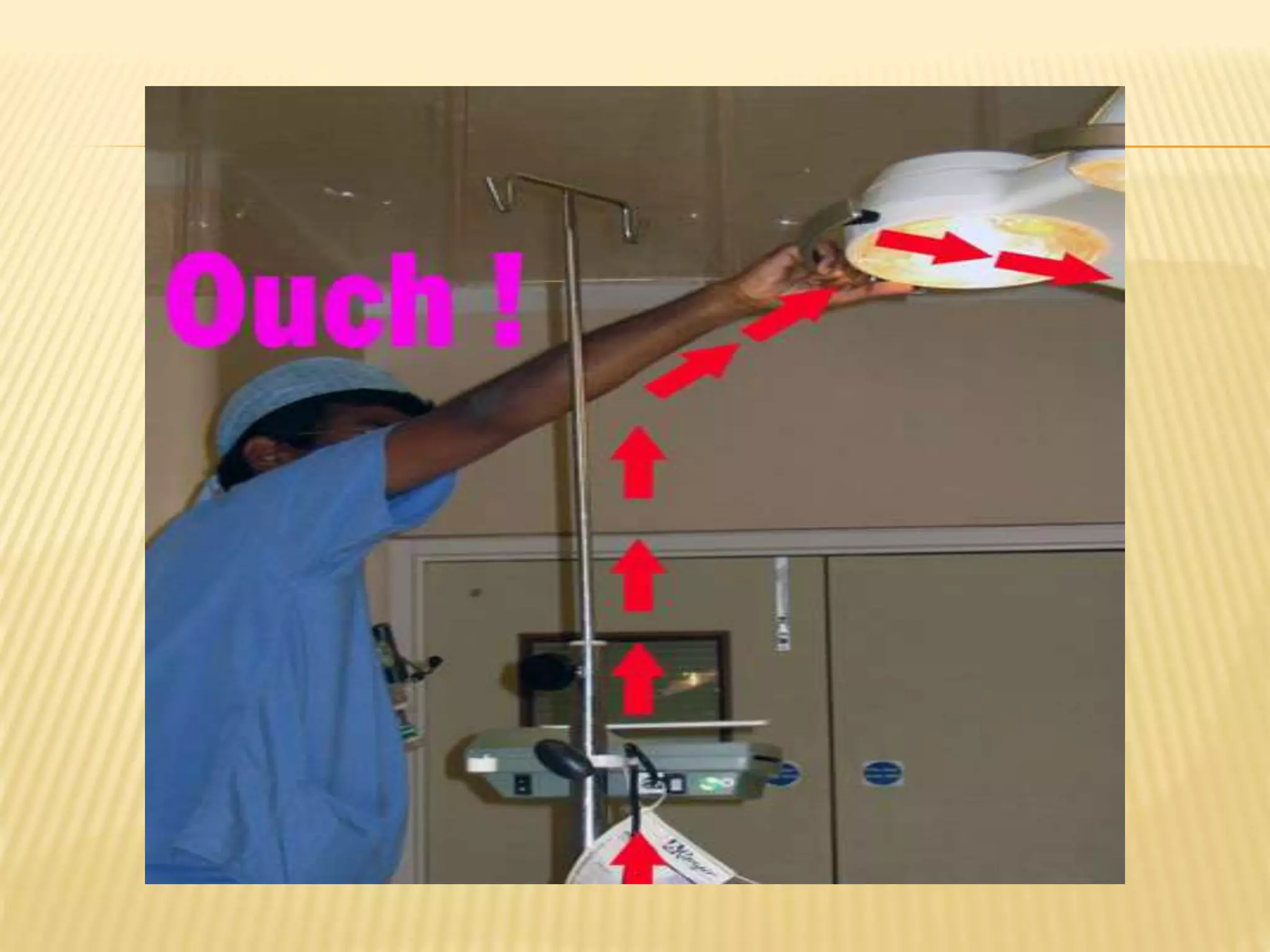


![GUPTA K, PREM KUMAR GV, BANSAL A, MEHTA Y
BURN INJURY BY DISPLACEMENT OF ELECTROCAUTERY PLATE.
INDIAN J ANAESTH [SERIAL ONLINE] 2011 [CITED 2013 FEB 2];55:634-5.
AVAILABLE
FROM: HTTP://WWW.IJAWEB.ORG/TEXT.ASP?2011/55/6/634/90636](https://image.slidesharecdn.com/electricalsafetyinor-170319090320/75/Electrical-safety-in-OR-76-2048.jpg)


![Abdelmalak B, Jagannathan
N, Arain FD, Cymbor S,
McLain R, Tetzlaff JE
Electromagnetic interference
in a pacemaker during
cauterization with the
coagulating, not cutting
mode.
J Anaesthesiol Clin
Pharmacol [serial online]
2011 [cited 2013 Feb
2];27:527-30. Available
from: http://www.joacp.org/te
xt.asp?2011/27/4/527/86600](https://image.slidesharecdn.com/electricalsafetyinor-170319090320/75/Electrical-safety-in-OR-87-2048.jpg)


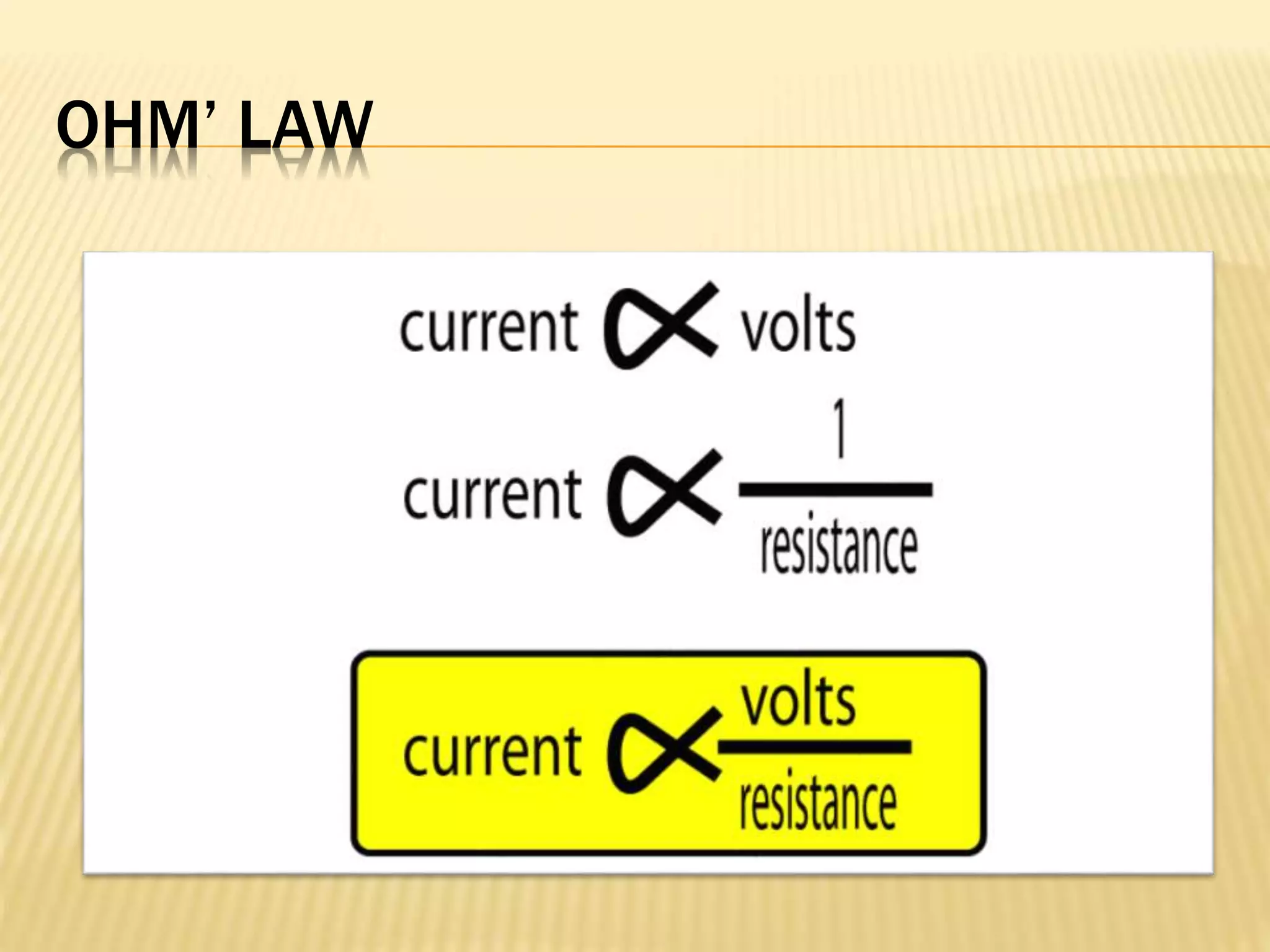
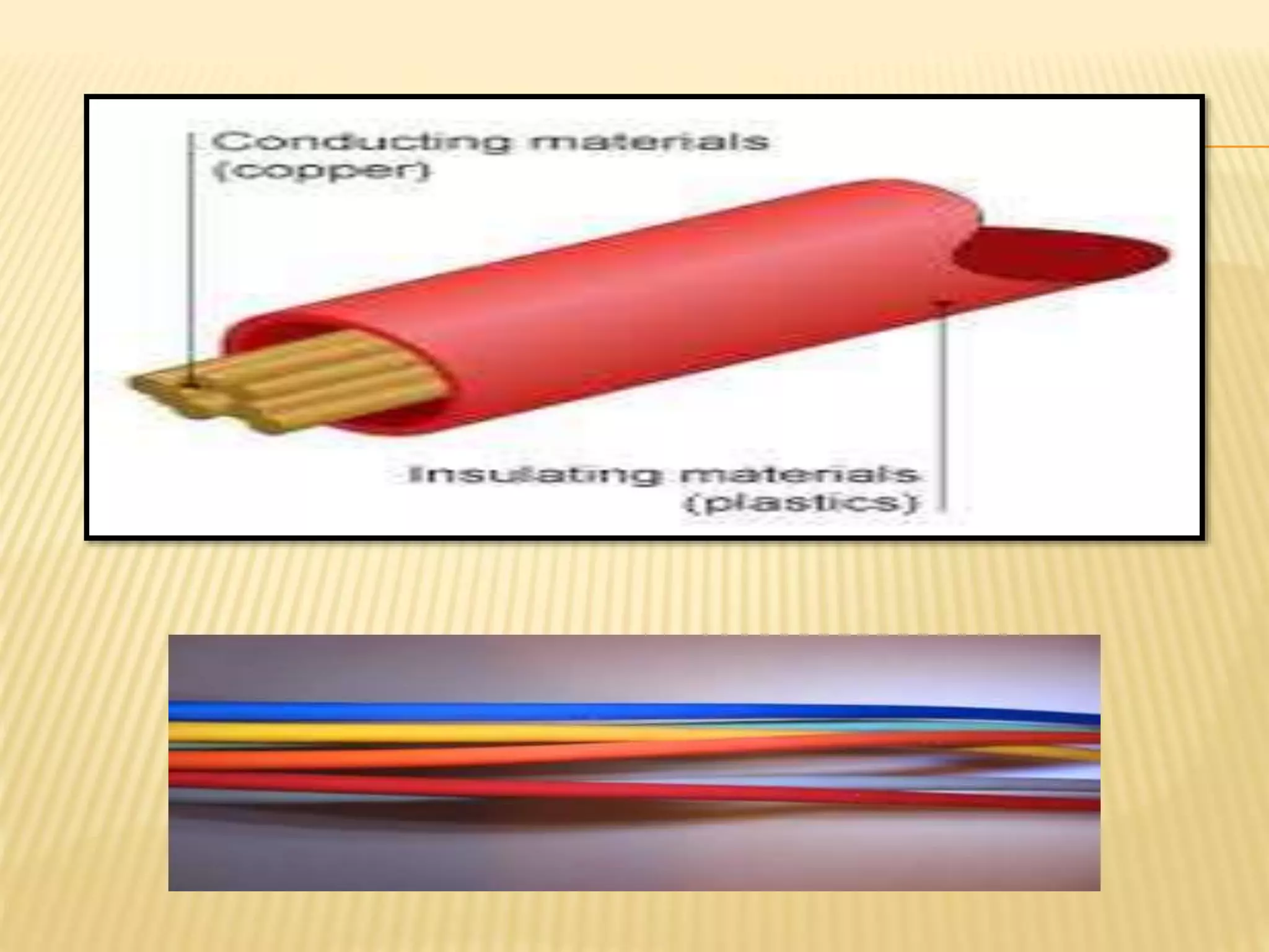
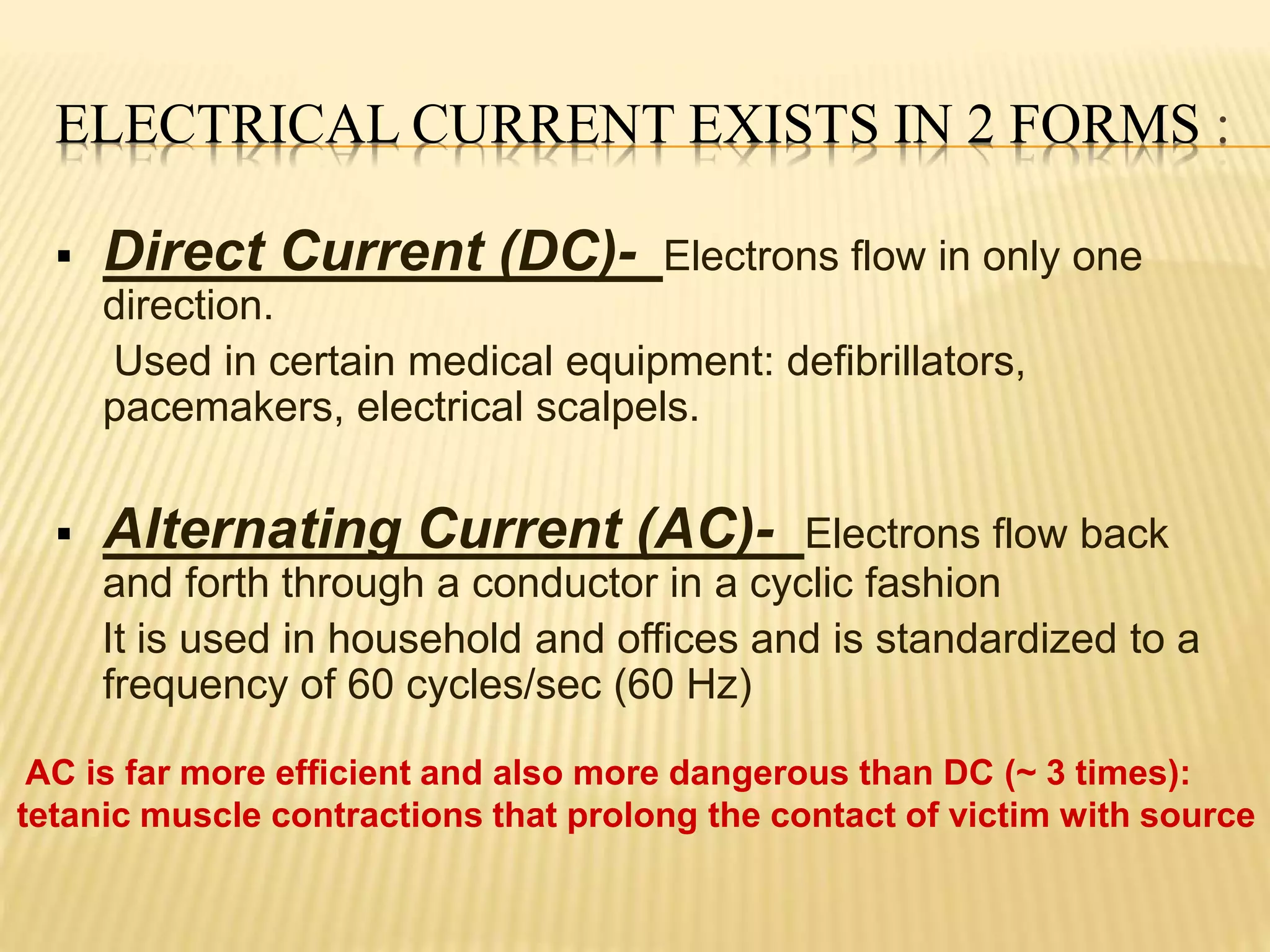
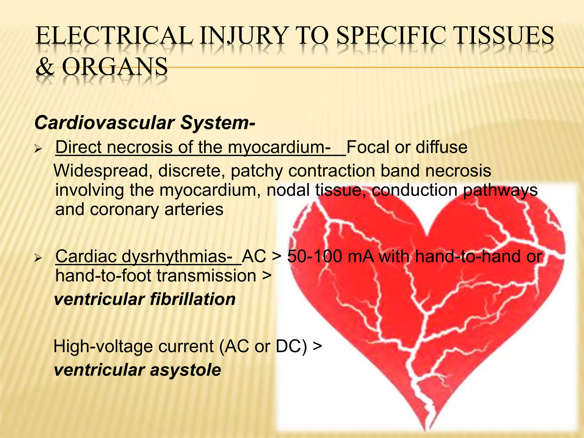
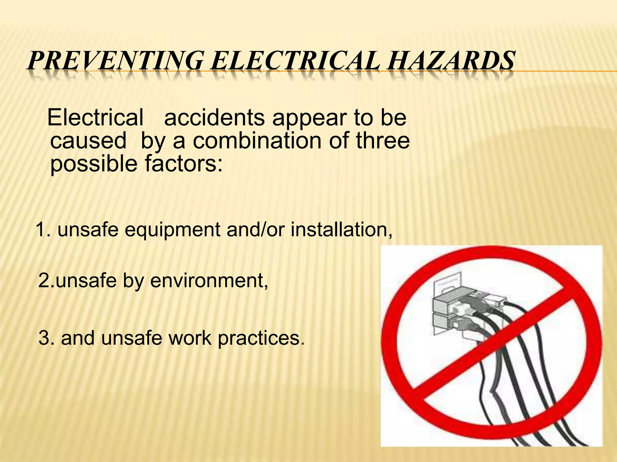
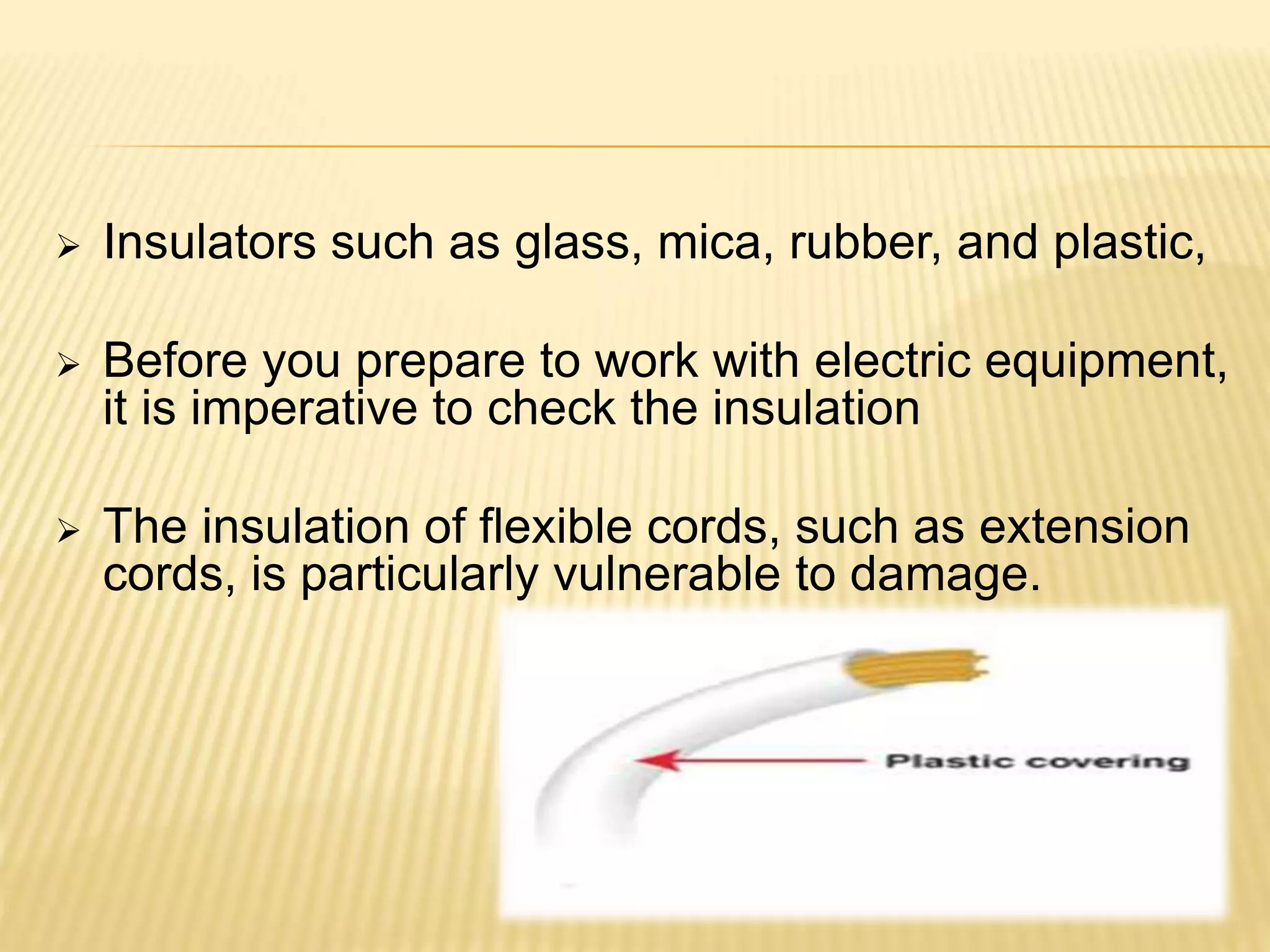
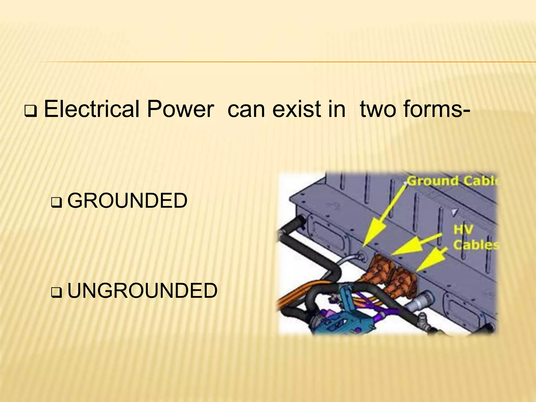
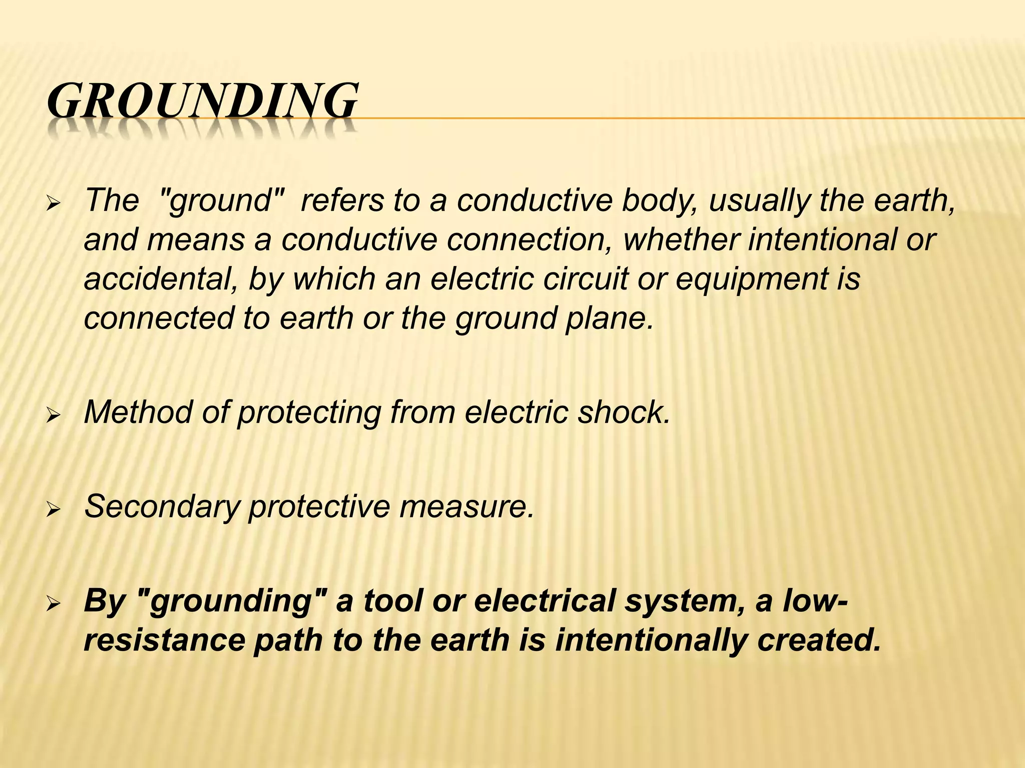
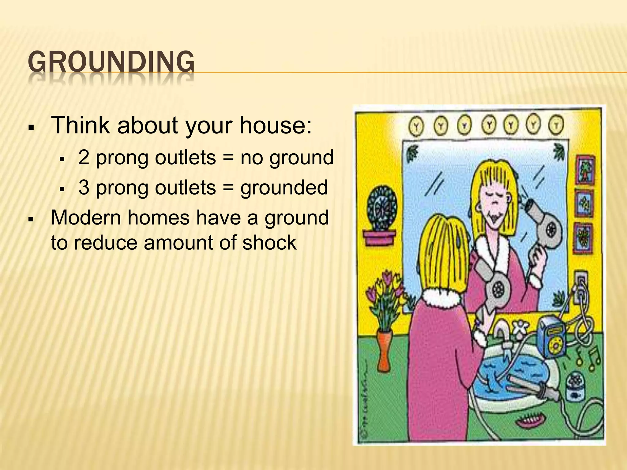
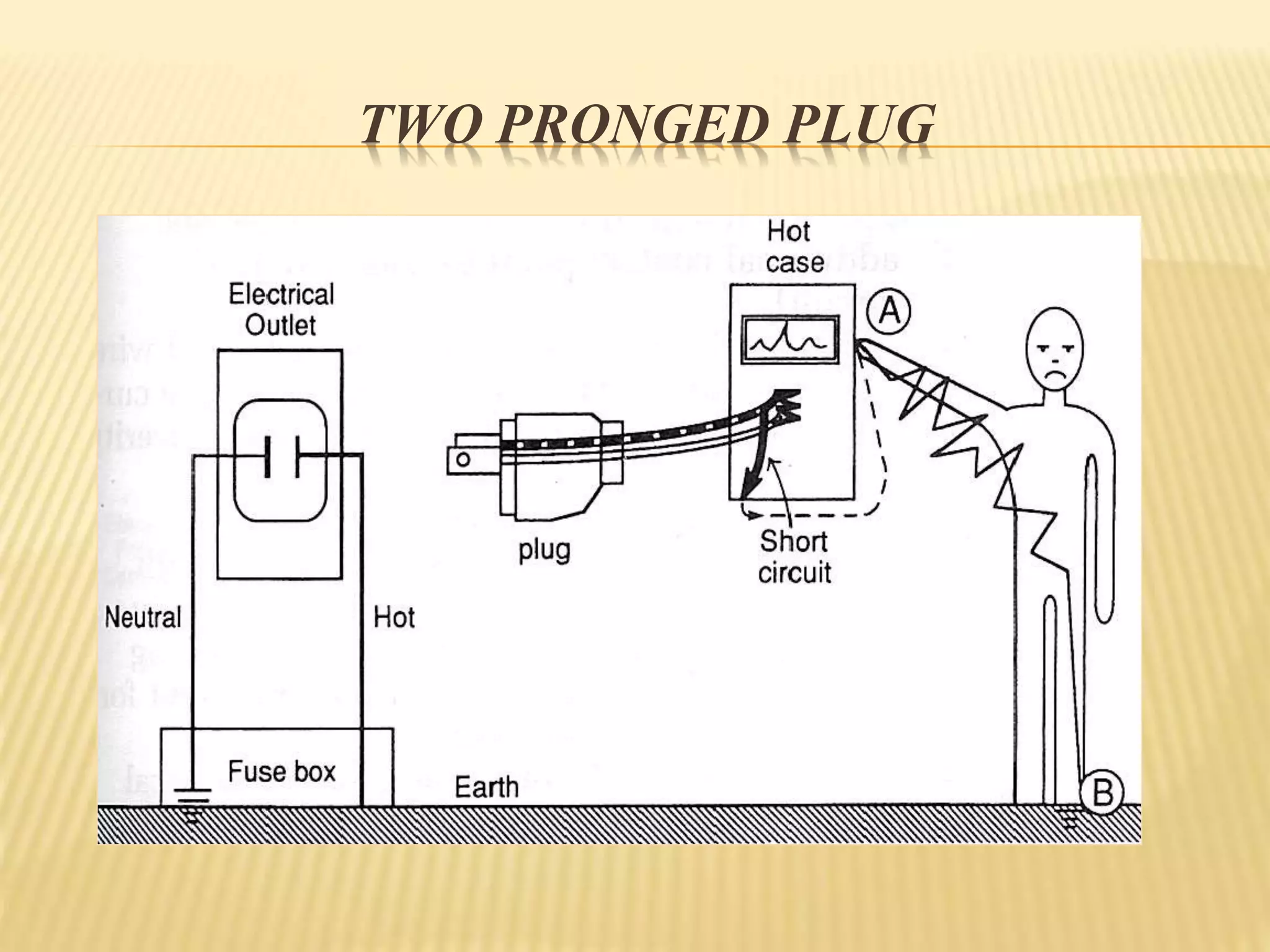
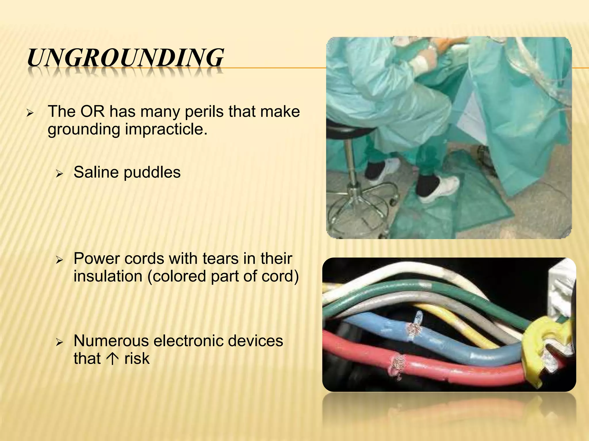
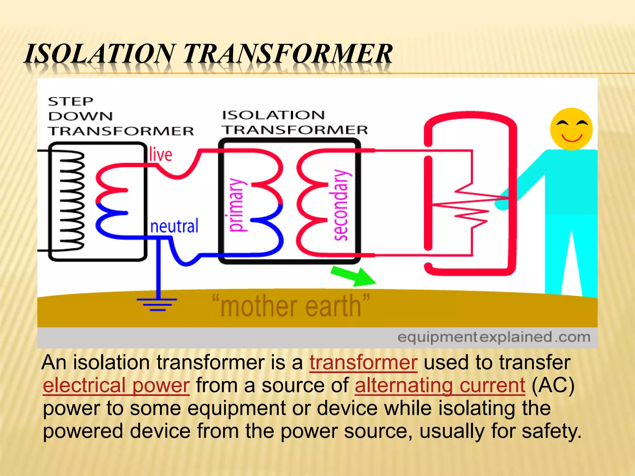
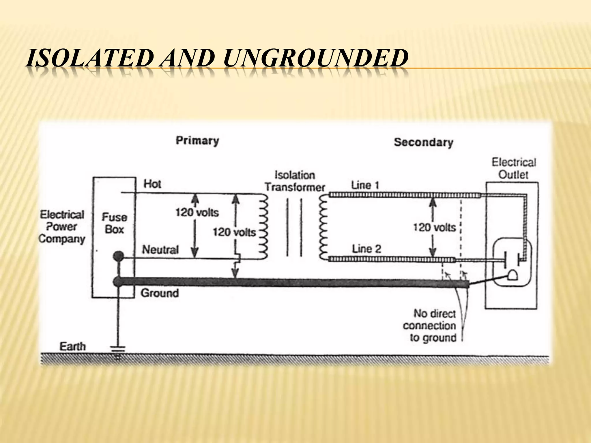
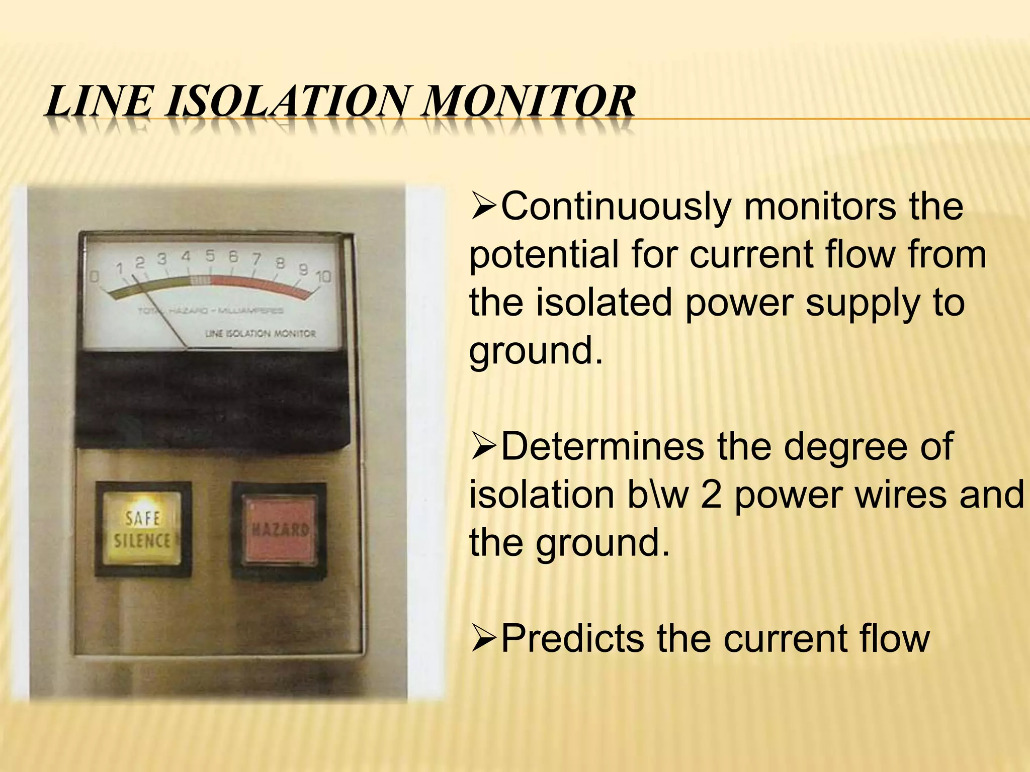
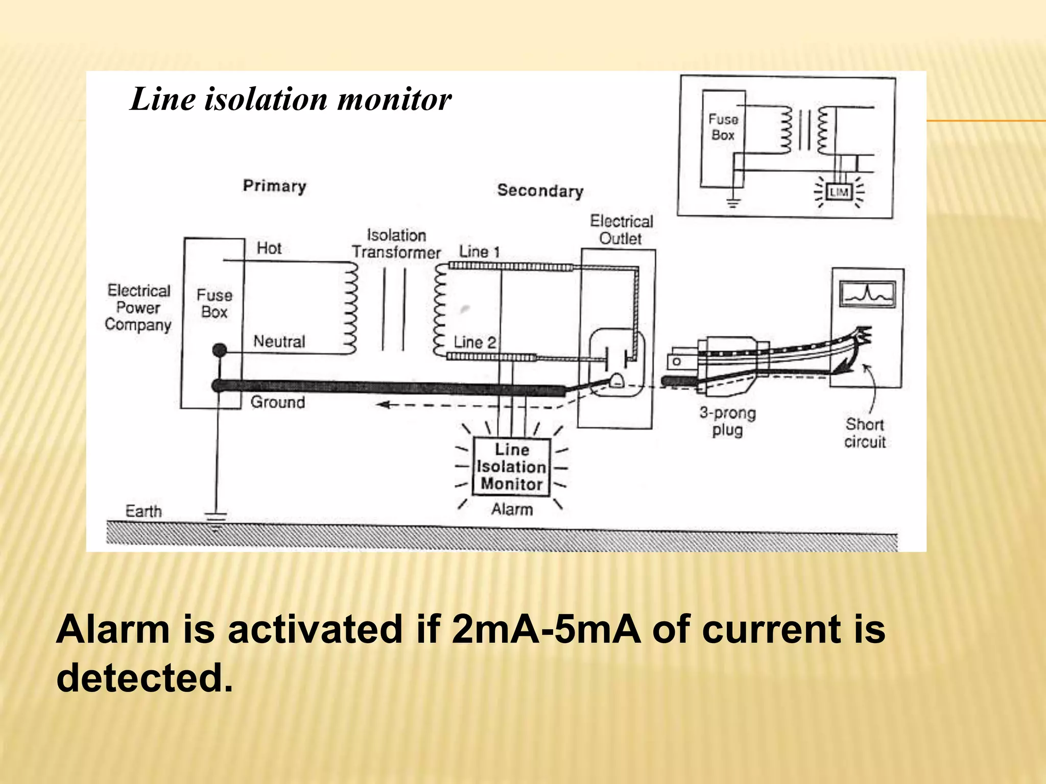
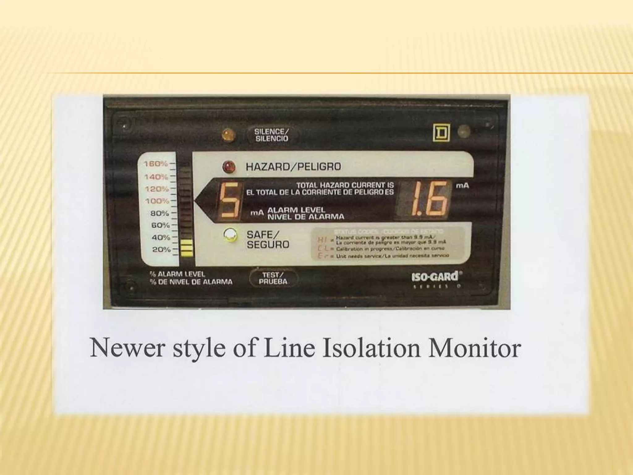
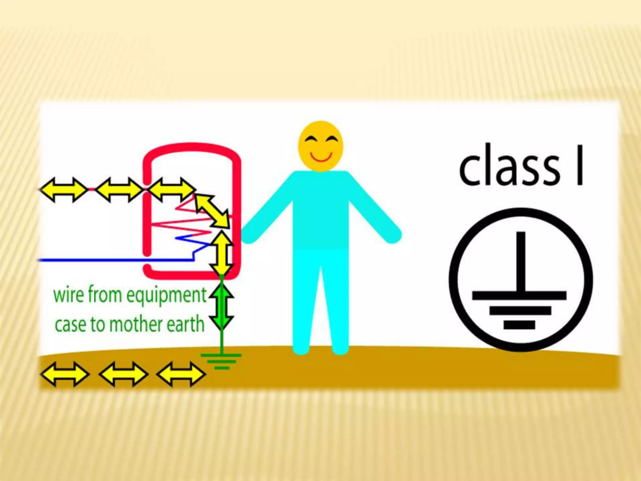
This document discusses electrical safety in operating rooms. It begins by introducing several doctors and the hospital. It then defines key electrical concepts like current, voltage, resistance, and Ohm's Law. It explains how electricity can enter the body through resistive or capacitive coupling. It discusses the types of electrical current, determinants of electrical injuries, and the effects on different body tissues and organs. The document concludes by outlining various prevention methods for electrical hazards like insulation, grounding, and use of protective devices.


![Apporach to lung biopsy [Auto-saved].pptx latest](https://cdn.slidesharecdn.com/ss_thumbnails/apporachtolungbiopsyauto-saved-251211225655-93258539-thumbnail.jpg?width=640&height=640&fit=bounds)


