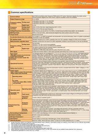
Downloaded 14 times

![Enhanced expandability
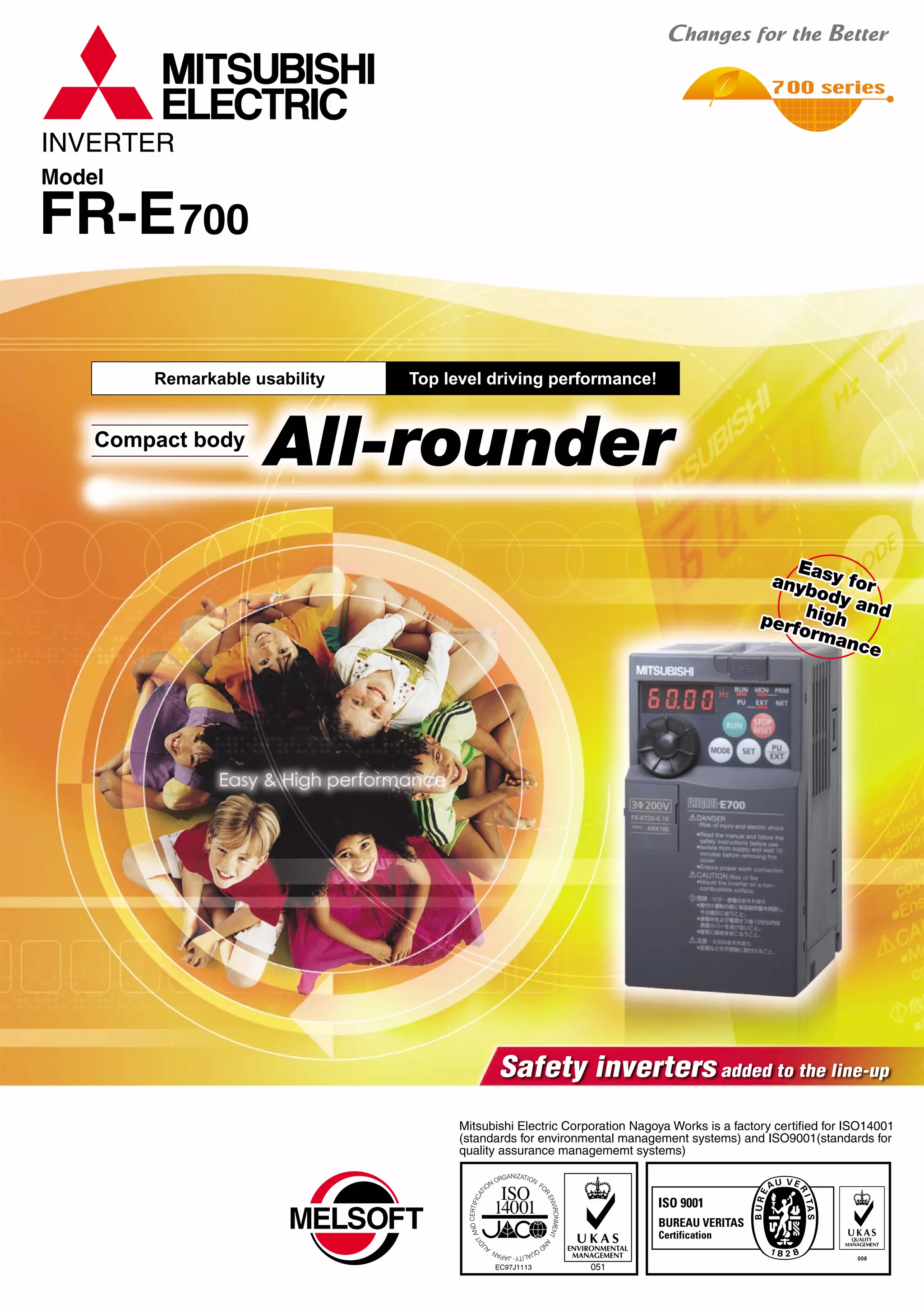
Mitsubishi inverters offer the expandability that answers to every need
Compact and space saving
Compact design expands flexibility of enclosure design.
Ensured maintenance
700 series are the pioneer of long life and high reliability.
Environment-friendly
Human and environment-friendly inverter
Full of useful functions
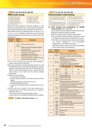
(1) A variety of plug-in options are mountable
Plug-in options supporting digital input, analog output extension, and a variety of communications provide extended functions which is
almost equivalent to the FR-A700 series. (One type of plug-in option can be mounted.)
•The design life of the cooling fan has been extended to 10
years*1. The life of the fan can be further extended utilizing the
it’s ON/OFF control.
•The design life of the capacitors has been extended to 10
years by adopting a capacitor that endures 5000 hours at
105˚C surrounding air temperature*1,*2.
(3) Control terminals are
selectable according to applications
(1) Compact body with
high performance function
Installation size is the same as
the conventional mode (FR-
E500 series) in consideration
of intercompatibility.
(7.5K or less)
(2) Side by side installation saves space
Space can be saved by side by side
no clearance installation*.
(4) Various kinds of networks are supported
EIA-485 (RS-485), ModbusRTU (equipped as standard), CC-Link,
PROFIBUS-DP, DeviceNet®, LONWORKS® (option)
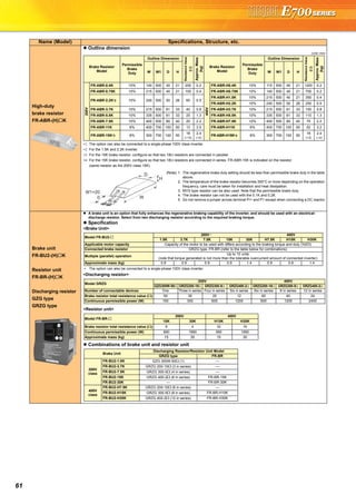
(1) Long-life design
A cooling fan is provided on top of the
inverter for all capacities requiring a
cooling fan*.
A cooling fan can be easily replaced
without disconnecting main circuit wires.
(3) Easy replacement of cooling fan
Since a wiring cover can be installed
after wiring, wiring work is easily done.
(4) Combed shaped wiring cover
Wiring of the control circuit when replacing the same series
inverter can be done by changing the terminal block.
(5) Removable control terminal block
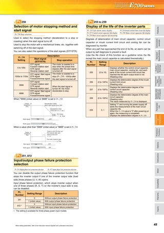
•Degrees of deterioration of main circuit capacitor, control circuit
capacitor, and inrush current limit circuit can be monitored.
•Trouble can be avoided with the self-diagnostic alarm*4 that is
output when the life span is near.
*4: Any one of main circuit capacitor, control circuit capacitor, inrush current limit circuit or
cooling fan reaches the output level, an alarm is output.
Capacity of the main circuit capacitor can be measured by setting parameter at a stop and
turning the power from off to on. Measuring the capacity enables an alarm to be output.
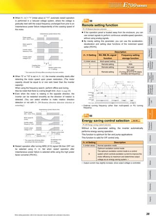
*: The inverter may trip and the motor may coast depending on the load condition.
Detection of coasting speed (frequency search function) prevents the motor speed from
decreasing at a restart, starting the motor smoothly with less output current.
*1: Surrounding air temperature : annual average 40˚C (free from corrosive gas, flammable gas,
oil mist, dust and dirt) Since the design life is a calculated value, it is not a guaranteed value.
*2: Output current : 80% of the inverter rated current
*: Cooling fans are equipped with FR-E720-1.5K (SC) or
more, FR-E740-1.5K (SC) or more, and FR-E720S-0.75K
(SC) or more.
(2) Leading life check function
The inverter is human and environment-friendly by being
compliance with the RoHS Directive.
•Automatic restart after instantaneous power failure function
with frequency search
•Brake sequence mode is useful for mechanical brake control of a lift.
•Regeneration avoidance function prevents regenerative overvoltage in a pressing machine.
•Optimum excitation control can save more energy with the maximum motor efficiency control.
•Main circuit power supply DC input can be connected to DC power supply.
•Enhanced I/O terminal function supports switchover of analog input (voltage / current).
•Password function is effective for parameter setting protection.
and so on
•Power-failure deceleration stop function/operation
continuation at instantaneous power failure function
The motor can be decelerated to a stop when a power failure
or undervoltage occurs to prevent the motor from coasting.
This function is useful to stop a motor at power failure as a fail
safe of machine tool, etc.
With the new operation continuation function at instantaneous
power failure, the motor continues running without coasting
even if an instantaneous power failure occurs during operation.
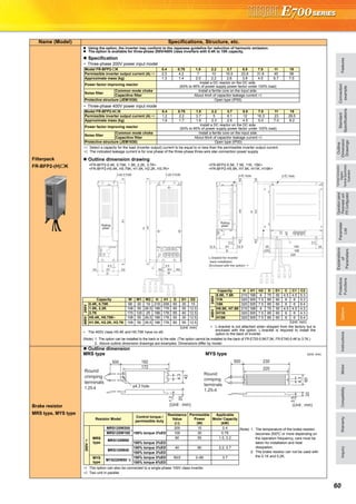
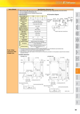
•The inverter with filterpack FR-BFP2 (a package of power factor
improving DC reactor, common mode choke and capacitive
filter) conforms to the Japanese harmonic suppression guideline.
•Noise filter option which is compatible with EMC Directive
(EN61800-3 2nd Environment Category C3) is available.
(2) Filter options
Plug-in option
Plug-in option dedicated front cover
Compatible Plug-in Options
•FR-A7AX E kit ...16-bit digital input
•FR-A7AY E kit ...Digital output
Extension analog output
•FR-A7AR E kit ...Relay output
•FR-A7NC E kit ...CC-Link
•FR-A7ND E kit ...DeviceNet
•FR-A7NP E kit ...PROFIBUS-DP
•FR-A7NL E kit ...LONWORKS
FR-E720-0.2K (SC) FR-E520-0.2K
•Life indication of life components
Components
Cooling fan
Main circuit smoothing capacitor
Printed board smoothing capacitor
Guideline of the FR-E700 Life
10 years
10 years
10 years
Guideline of JEMA*3
2 to 3 years
5 years
5 years
*3: Excerpts from “Periodic check of the transistorized inverter” of JEMA (Japan Electrical Manufacturer’s Association)
FR-E500 series FR-E700 series
Input voltage Output frequency
Motor speed
Output current
Input voltage Output frequency
Motor speed
Output current
LONWORKS® is a registered trademark of Echelon Corporation, DeviceNet® is of ODVA,
and PROFIBUS is of PROFIBUS User Organization.
Other company and product names herein are the trademarks of their respective owners.
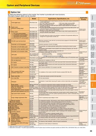
These plug-in options are supported by the standard control circuit terminal model.
Terminal
card
128mm
Terminal cards other than standard terminal
such as two port RS-485 terminal are
available as options.
A terminal card is removable and can be
easily replaced from a standard terminal
card.
*: Use the inverter at the surrounding air temperature
of 40˚C or less.
(1) Compliance with the EU Restriction
of Hazardous Substances (RoHS)
[ For the FR-E700 series, use the "FR-A7 E kit" which is a set of optional board and dedicated front cover.]
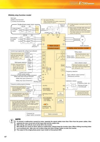
(2) Safety stop function (FR-E700-SC)
•Spring clamp terminals are adopted as control circuit terminals.
Spring clamp terminals are highly reliable and can be easily wired.
•The FR-E700-SC series is compliant to the EU Machinery Directive
without the addition of previously required external devices.
Operation of an external Emergency Stop device results in a
highly reliable immediate shutoff of the D700's output to the motor.
This safety stop function conforms to the following standards.
EN ISO 13849-1 Category 3 / PLd
EN62061 / IEC61508 SIL2
Provided by the user (present) FR-D700
Safety function
is equipped
Emergency stop Emergency stop
For conventional modelFor conventional model...
Two MCs were necessaryTwo MCs were necessary
For conventional model...
Two MCs were necessary
•High cost
•Maintenance of two MCs
was necessary
•Installation space was necessary
•Magnetic contactor (MC)
•Emergency stop wiring
Only one MC is recommendedOnly one MC is recommended
instead of twoinstead of two.
Although MC is not requiredAlthough MC is not required
for the safety stop functionfor the safety stop function.
Only one MC is recommended
instead of two.
Although MC is not required
for the safety stop function.
•Cost reduction
•Maintenance of one MC
•Installation space is reduced
*: Approved safety relay unit
*
Peripheral
device
Mitsubishi magnetic
contactors
•Offer a selection of small frames
•Offer a line-up of safety contactors
•Support with low-level load (auxiliary contact)
•Support many international regulations as a standard model
Refer to page 62 for the selection.
Enhanced functions for all sorts of applications
3 4
FeaturesOptionsInstructionsMotorCompatibilityWarrantyInquiry
Connection
example
Standard
Specifications
Operationpanel
Parameterunit
FRConfigurator
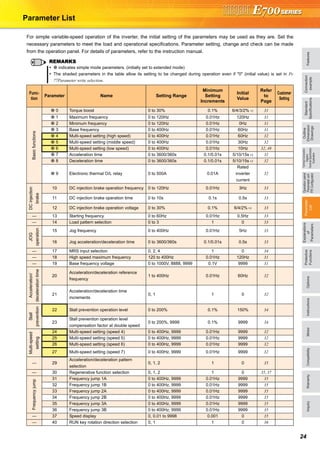
Parameter
List
Protective
Functions
Explanations
of
Parameters
TerminalConnection
Diagram
TerminalSpecification
Explanation
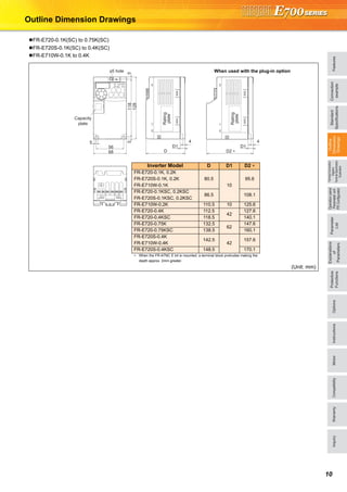
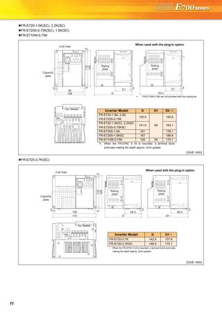
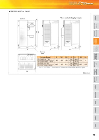
Outline
Dimension
Drawings](https://image.slidesharecdn.com/catalog-fr-e700-mitsubishi-160425074315/85/Catalog-Inverter-FR-E700-Mitsubishi-Electric-Beeteco-com-3-320.jpg)

![21
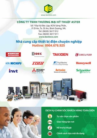
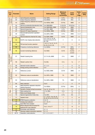
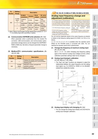
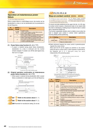
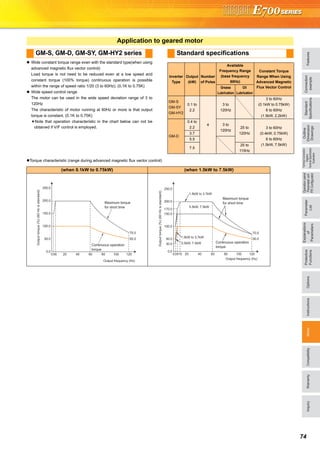
Basic operation of the operation panel
STOP
Operation mode switchover
ParametersettingFaultshistoryMonitor/frequencysetting
At powering ON (External operation mode)
PU operation mode
(output frequency monitor)
Parameter setting mode
PU Jog operation mode
Output current monitor Output voltage monitor
Display the
present setting
Value change
Value change
Parameter write is completed!!
Parameter and a setting value
flicker alternately.
Parameter clear All parameter
clear
Faults history clear
Initial value
change list
(Example)
(Example)
Frequency setting has been
written and completed!!
and frequency flicker.
[Operation for displaying faults history]
Past eight faults can be displayed.
(The latest fault is ended by ".".)
When no fault history exists, is displayed.](https://image.slidesharecdn.com/catalog-fr-e700-mitsubishi-160425074315/85/Catalog-Inverter-FR-E700-Mitsubishi-Electric-Beeteco-com-19-320.jpg)
![FeaturesOptionsInstructionsMotorCompatibilityWarrantyInquiry
Standard
Specifications
Operationpanel
Parameterunit
FRConfigurator
Parameter
List
Protective
Functions
Explanations
of
Parameters
TerminalConnection
Diagram
TerminalSpecification
Explanation
Outline
Dimension
Drawings
Connection
example
22
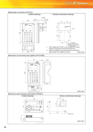
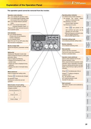
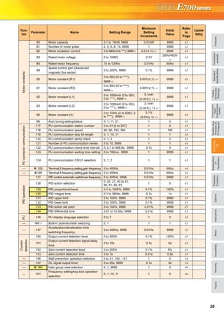
Explanations of Parameter unit
The parameter unit is a convenient tool for inverter setting
such as direct input method with a numeric keypad,
operation status indication, and help function.
Eight languages can be displayed.
Parameter setting values of maximum of three inverters can
be stored.
With the FR-PU07BB(-L), parameter check and setting
change can be made without connecting a power supply to
the inverter. Use AA nickel hydride batteries, AA alkali
batteries, or AC adapter separately available as power
supply.
Since the shape is specially designed for portable use, it is
easy to work with the FR-PU07BB(-L) in hand.
∗ The parameter unit connection cable FR-CB20 is required for connecting to
the inverter. (Parameter unit connection cable FR-CB203(3m) is enclosed
with FR-PU07BB(-L).)
∗ To use a parameter unit with battery pack (FR-PU07BB) outside Japan, order
a "FR-PU07BB-L" (parameter unit type indicated on the package has L at the
end). Since enclosed batteries may conflict with laws in countries to be used
(new EU Directive on batteries and accumulators, etc.), batteries are not
enclosed with an FR-PU07BB-L.
Main functions
∗ Available function differs by the inverter. Please refer to the instruction manual of the inverter and the parameter unit.
Parameter unit (FR-PU07), parameter unit with battery pack (FR-PU07BB(-L))
POWER lamp
Lit when the power turns on.
Monitor
Liquid crystal display
(16 characters 4 lines with backlight)
Interactive parameter setting
Trouble shooting guidance
Monitor (frequency, current, power, etc.)
ALARM lamp
Lit to indicate an inverter alarm occurrence.
(Refer to the table
on the right)
Operation keys
FR-PU07
FR-PU07BB
Key Description
Use for parameter setting
Press to choose the parameter setting mode.
First priority monitor is displayed.
In the initial setting, the output frequency is displayed.
Operation cancel key
Used to display the function menu.
A variety of functions can be used on the function menu.
Used to shift to the next item in the setting or monitoring mode.
to Used to enter a frequency, parameter number or set value.
Inverter operates in the External operation mode.
Used to select the PU operation mode to display the frequency
setting screen.
Used to keep on increasing or decreasing the running
frequency. Hold down to vary the frequency.
Press either of these keys on the parameter setting mode
screen to change the parameter setting value sequentially.
On the selecting screen, these keys are used to move the cursor.
Hold down and press either of these keys to advance
or return the display screen one page.
Forward rotation command key.
Reverse rotation command key.
Stop command key.
Used to reset the inverter when an alarm occurs.
Used to write a set value in the setting mode.
Used as a clear key in the all parameter clear or alarm history
clear mode.
Used as a decimal point when entering numerical value.
Used as a parameter number read key in the setting mode.
Used as an item select key on the menu screen such as
parameter list or monitoring list.
Used as an alarm definition display key in the alarm history
display mode.
Used as a command voltage read key in the calibration mode.
Function Description
Monitor 6 types of monitors appear by simply pressing .
Frequency setting
For PU operation mode and External/PU combined operation mode (Pr.79 = "3"), frequency setting is available.
Settings is performed by the direct setting, which sets frequency directly by to , and the step setting, which
sets frequency continuously by .
Parameter Setting
Reading parameter and changing setting values are easily done. To change the setting value of an parameter, specify
the parameter number, or select a parameter from the functional parameter list.
Batch copy
FR-PU07 (PU07BB) reads parameter settings of an inverter, and stores three different parameter settings.
FR-PU07 (PU07BB) can also copy the stored parameter setting to another inverter of the same series, or verify its
stored parameter setting against the parameter setting stored in an inverter.
Operation
Switching between External operation mode [EXT] and PU operation mode [PU] is easy.
Start/stop is enabled during PU operation mode and External/PU operation mode (Pr.79 = "3").](https://image.slidesharecdn.com/catalog-fr-e700-mitsubishi-160425074315/85/Catalog-Inverter-FR-E700-Mitsubishi-Electric-Beeteco-com-20-320.jpg)
![23
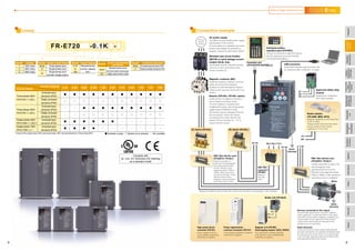
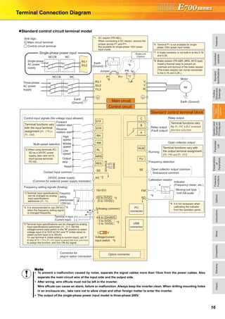
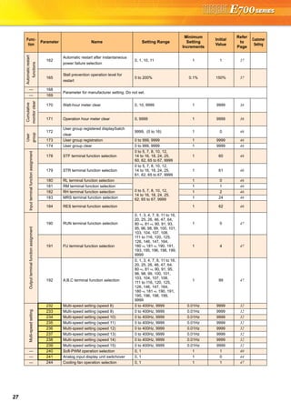
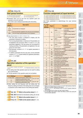
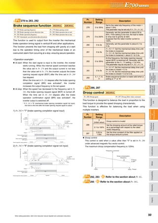
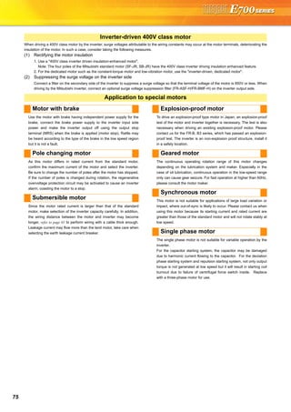
FR Configurator (INVERTER SETUP SOFTWARE)
FR Configurator is software offers an easy operating environment.
Can be utilized effectively from inverter setting up to maintenance.
Parameter setting, monitoring, etc. can be performed on a display of Windows *2 personal computer.
A personal computer and an inverter can be easily connected with a USB cable.
(RS-485 communication *3 using PU connector is also available.)
∗1 FR Configurator does not support the safety stop function model.
∗2 Microsoft, Windows, Microsoft Windows2000, Microsoft Windows XP, Microsoft Windows Vista are registered
trademarks of Microsoft Corporation in the United States and/or other countries.
∗3 RS-485⇔RS-232C converter is required.
Desired function can be performed just after a start-up of
the software.
(1) Open the recent used
System File
(2) Perform Easy Setup
(3) Perform each functions
(4) Help
From station number to parameter setting, setting with
wizard style dialog (interactive) is available.
Procedure for Easy Setup
(1) System File setting
(2) Communication setting
(3) Inverter recognition
(4) Control method selection
(5) Motor setting
(6) Start command,
frequency command
setting
(7) Parameter setting
In Navigation area, switching ONLINE/
OFFLINE and changing operation mode can
be performed.
(1) Frequency setting and forward/reverse
rotation [Test operation]
(2) Display the connected inverter in tree
view [System List]
(3) Function setting without regard to
parameter number [Basic setting]
(4) Estimates the cause of trouble, and
suggest counteraction. [Troubleshooting]
In Monitor area, inverter status can be monitored.
(1) Displays monitor data in
waveform
Displays current
waveform with High
Speed graph function
[Graph]
(2) Monitors the status of I/O
terminals. [I/O Terminal
Monitor]
(3) Displays multiple data in batch. [Batch Monitor]
In System area, parameter setting, Diagnosis,
Troubleshooting, etc. can be performed.
(1) Parameter reading,
writing, verification,
Functional List and
Individual List display
are available.
[Parameter List]
(2) Displays alarm history
and monitor value at
each alarm
occurrence. [Diagnosis]
(3) Parameter setting conversion from conventional
models [Convert]
Setting wizard can set parameters with wizard style dialog
(interactive). Inputting or selecting required items for each
function, parameter setting can be made, without regard to
parameter number.
Displays operating instructions and details of each
parameters.
FR-SW3-SETUP-WE (for 700 series) and FR-SW1-SETUP-WE (500 series) can be installed from the FR Configurator SW3.
FR-SW3-SETUP-WE is available for download (free of charge) from the below URL on the internet. FR Configurator SW3 (FR-SW3-SETUP-
WE or FR-SW1-SETUP-WE) needs to be installed to the personal computer prior to updating the software. Also, user registration is required
for the download (free of charge.) (Registration is free of charge.)
MELFANSweb homepage address http://www.MitsubishiElectric.co.jp/melfansweb
FR-SW3-SETUP-WE *1
(Microsoft®
Windows®
2000 Professional SP4 or later, XP Home Edition SP2 or later, XP Professional SP2 or later
Windows Vista®
SP1 or later supported)
USB cable USB connector
<How to open the USB connector cover>
Pull the cover in the direction of arrow. Then turn it upward.
Startup
Easy Setup
Navigation area
Monitor area
System area
Setting wizard
Help](https://image.slidesharecdn.com/catalog-fr-e700-mitsubishi-160425074315/85/Catalog-Inverter-FR-E700-Mitsubishi-Electric-Beeteco-com-21-320.jpg)
![FeaturesOptionsInstructionsMotorCompatibilityWarrantyInquiry
Standard
Specifications
Operationpanel
Parameterunit
FRConfigurator
Parameter
List
Protective
Functions
Explanations
of
Parameters
TerminalConnection
Diagram
TerminalSpecification
Explanation
Outline
Dimension
Drawings
Connection
example
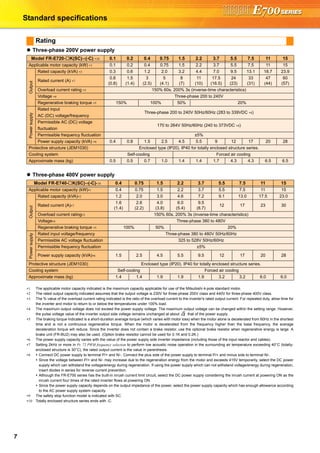
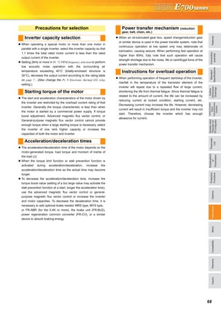
32When setting parameters, refer to the instruction manual (Applied) and understand instructions.
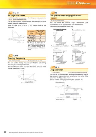
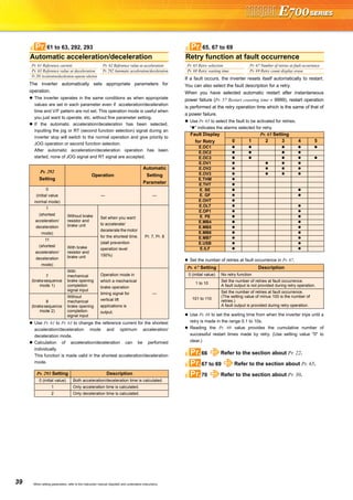
Can be used to change the preset speed in the parameter with the
contact signals.
Any speed can be selected by merely turning on-off the contact
signals (RH, RM, RL, REX signals).
Operation is performed at the frequency set in Pr. 4 when the RH
signal turns on, Pr. 5 when the RM signal turns on, and Pr. 6 when
the RL signal turns on.
Used to set motor acceleration/deceleration time.
Set a larger value for a slower speed increase/decrease or a
smaller value for a faster speed increase/decrease.
Use Pr. 7 Acceleration time to set the acceleration time to reach Pr. 20
Acceleration/deceleration reference frequency from 0Hz
Use Pr. 8 Deceleration time to set the deceleration time taken to
reach 0Hz from Pr. 20 Acceleration/deceleration reference frequency.
When RT signal is off, automatic switching of the acceleration/
deceleration time is available with Pr. 147.
Set the current of the electronic thermal relay function to protect
the motor from overheat. This feature provides the optimum
protective characteristics, including reduced motor cooling
capability, at low speed.
This function detects the overload (overheat) of the motor, stops the
operation of the inverter's output transistor, and stops the output.
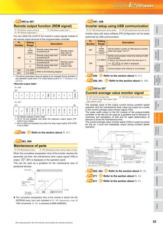
Set the rated current [A] of the motor in Pr. 9.
(If the motor has both 50Hz and 60Hz rating and the Pr. 3 Base
frequency is set to 60Hz, set the 1.1 times of the 60Hz rated motor
current.)
Set "0" in Pr. 9 to make the electronic thermal relay function invalid
when using a motor with an external thermal relay, etc. (Note that
the output transistor protection of the inverter functions (E.THT).)
When using a Mitsubishi constant-torque motor
1) Set any of "1, 13 to 16, 50, 53, 54" in Pr. 71. (This provides a
100% continuous torque characteristic in the low-speed range.)
2) Set the rated current of the motor in Pr. 9.
When the RT signal is on, thermal protection is provided based on
the Pr. 51 setting.
Use this function when running two motors of different rated currents
individually by a single inverter. (When running two motors together,
use external thermal relays.)
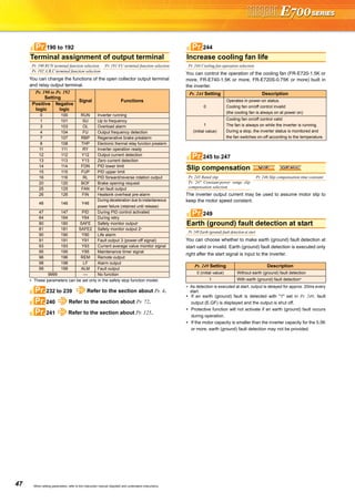
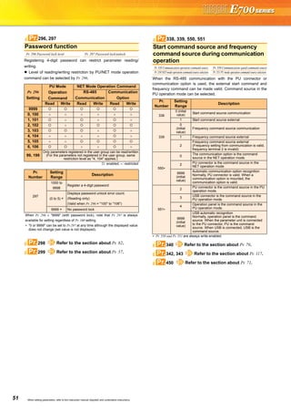
Multi-speed setting operation
Pr. 4 Multi-speed setting (high speed) Pr. 5Multi-speed setting (middle speed)
Pr. 6 Multi-speed setting (low speed) Pr. 24 Multi-speed setting (speed 4)
Pr. 25 Multi-speed setting (speed 5) Pr. 26 Multi-speed setting (speed 6)
Pr. 27 Multi-speed setting (speed 7) Pr. 232 Multi-speed setting (speed 8)
Pr. 233 Multi-speed setting (speed 9) Pr. 234 Multi-speed setting (speed 10)
Pr. 235 Multi-speed setting (speed 11) Pr. 236 Multi-speed setting (speed 12)
Pr. 237 Multi-speed setting (speed 13) Pr. 238 Multi-speed setting (speed 14)
Pr. 239 Multi-speed setting (speed 15)
Frequency from 4 speed to 15 speed can be set according to the
combination of the RH, RM, RL and REX signals. Set the running
frequencies in Pr. 24 to Pr. 27, Pr. 232 to Pr. 239 (In the initial value
setting, speed 4 to speed 15 are unavailable)
∗1 When "9999" is set in Pr. 232 Multi-speed setting (speed 8), operation is
performed at frequency set in Pr. 6 when RH, RM and RL are turned
OFF and REX is turned ON.
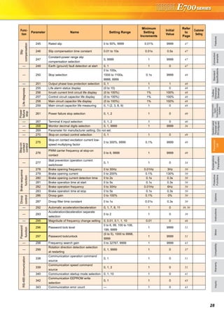
4 to 6, 24 to 27, 232 to 239Pr.
ON
ON
ON
Outputfrequency(Hz)
Speed 1
(High speed)
Speed 2
(Middle speed)
Speed 3
(Low speed)
RH
RM
RL
Time
ON ON ON
ON ON
ONON
ON
Speed 4
Speed 5
Speed 6
Speed 7
Time
Speed 8
Speed 9
Speed 10
Speed 11
Speed 12
Speed 13
Speed 14
Speed 15
ONON ON ON ON ON ON ON
ON ON ON ON
ON ON ON ON
ON ON ON ON
RH
RM
RL
REX
Outputfrequency(Hz)
*1
Acceleration/deceleration time setting
Pr. 7 Acceleration time Pr. 8 Deceleration time
Pr. 20 Acceleration/deceleration reference frequency Pr. 21 Acceleration/deceleration time increments
Pr. 44 Second acceleration/deceleration time Pr. 45 Second deceleration time
Pr. 147 Acceleration/deceleration time switching frequency
Motor protection from overheat
(electronic thermal relay function)
Pr. 9 Electronic thermal O/L relay Pr. 51 Second electronic thermal O/L relay
7, 8, 20, 21, 44, 45, 147Pr.
Running
frequency
Acceleration time
Pr. 7, Pr. 44
Deceleration time
Pr. 8, Pr. 45
Time
Pr. 20
(60Hz)
(Hz)
Output
frequency
Pr. 21
Setting
Description
0
(initial
value)
Increments:
0.1s
Range:
0 to 3600s
Increments
and setting
range of
acceleration/
deceleration
time setting
can be
changed.
1
Increments:
0.01s
Range: 0 to
360s
Time
Acceleration time Deceleration time
Output frequency
(Hz)
Set
frequency
Pr. 147
setting
Pr. 7 Pr. 44 Pr. 44
(Pr. 45)
Pr. 8
9, 51Pr.](https://image.slidesharecdn.com/catalog-fr-e700-mitsubishi-160425074315/85/Catalog-Inverter-FR-E700-Mitsubishi-Electric-Beeteco-com-30-320.jpg)
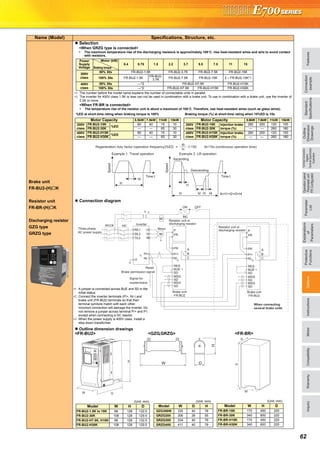
![35 When setting parameters, refer to the instruction manual (Applied) and understand instructions.
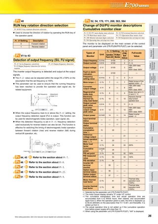
You can set the acceleration/deceleration pattern suitable for
application.
When making frequent starts/stops, use the optional brake resistor
to increase the regeneration capability. (0.4K or more)
Use a power regeneration common converter (FR-CV) for continuous
operation in regeneration status.
Use a high efficiency converter (FR-HC) for harmonic suppression
and power factor improvement.
∗1 The brake duty varies according to the inverter capacity.
∗2 7.5K or less/11K or more
∗3 Available only for the FR-E720-3.7K
Up to three areas may be set, with the jump frequencies set to either
the top or bottom point of each area.
The settings of frequency jumps 1A, 2A, 3A are jump points, and
operation is performed at these frequencies in the jump areas.
Frequency jump is not performed if the initial value is set to "9999".
During acceleration/deceleration, the running frequency within the
set area is valid.
The monitor display and frequency setting of the PU (FR-PU04/
FR-PU07) can be changed to the machine speed.
To display the machine speed, set in Pr. 37 the machine speed for
60Hz operation.
∗1 Machine speed conversion formula..........Pr.37 x frequency/60Hz
∗2 Hz is displayed in 0.01Hz increments and machine speed is in 0.001.
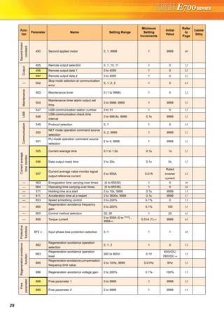
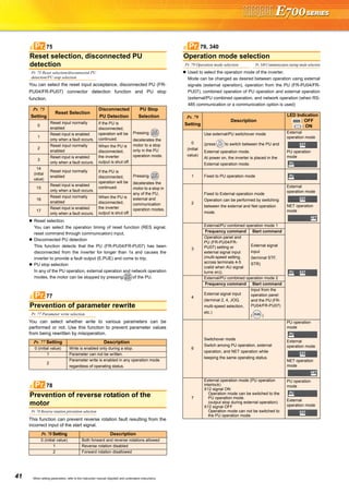
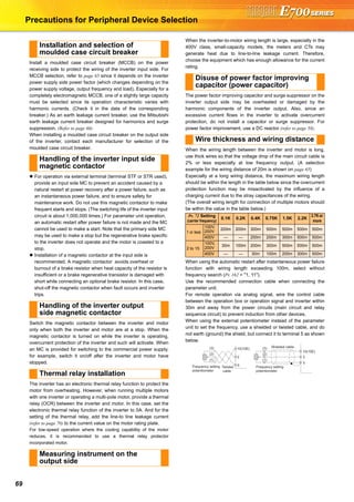
Acceleration/deceleration pattern
Pr. 29 Acceleration/deceleration pattern selection
Linear acceleration/deceleration (setting
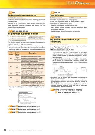
"0", initial value)
For the inverter operation, the output
frequency is made to change linearly (linear
acceleration/deceleration) to prevent the
motor and inverter from excessive stress to
reach the set frequency during acceleration,
deceleration, etc. when frequency changes.
S-pattern acceleration/deceleration A
(setting "1")
For machine tool spindle applications, etc.
Used when acceleration/deceleration
must be made in a short time to a high-
speed range of not lower than Pr. 3 Base
frequency (fb).
S-pattern acceleration/deceleration B
(setting "2")
For prevention of load shifting in
conveyor and other applications.
Since acceleration/deceleration is always
made in an S shape from current
frequency (f2) to target frequency (f1),
this function eases shock produced at
acceleration/deceleration and is effective
for load collapse prevention, etc.
Selection of regeneration unit
Pr. 30 Regenerative function selection Pr. 70 Special regenerative brake duty
Pr. 30
Set Value
Pr. 70
Set Value
Regeneration Unit
0
(initial
value)
∗1
Brake resistor (MRS type, MYS type)
Brake unit (FR-BU2)
Power regeneration common converter (FR-CV)
High power factor converter (FR-HC)
1
6%
Brake resistor (MYS type)
(When using at 100% torque 6%ED ) ∗3
10/6% ∗2 High-duty brake resistor (FR-ABR)
2 —
High power factor converter (FR-HC)
(when an automatic restart after
instantaneous power failure is selected)
29Pr.
(Hz)
Time
Setting value "0"
[Linear acceleration/
deceleration]
Outputfrequency
fb
(Hz)
Setting value "1"
[S-pattern acceleration/
deceleration A]
Outputfrequency
Time
f1
(Hz)(Hz)
f2
SetfrequencyOutputfrequency
Time
Setting value "2"
[S-pattern acceleration/
deceleration B]
30, 70Pr.
Avoid mechanical resonance points
(frequency jump)
Pr. 31 Frequency jump 1A Pr. 32 Frequency jump 1B
Pr. 33 Frequency jump 2A Pr. 34 Frequency jump 2B
Pr. 35 Frequency jump 3A Pr. 36 Frequency jump 3B
When it is desired to avoid
resonance attributable to
the natural frequency of a
mechanical system, these
parameters allow
resonant frequencies to
be jumped.
Speed display
Pr. 37 Speed display
Pr. 37
Setting
Output
Frequency
Monitor
Set
Frequency
Monitor
Frequency
Setting
Parameter
Setting
0 (initial
value)
Hz Hz Hz
Hz
0.01 to
9998
Machine
speed ∗1
Machine
speed ∗1
Machine
speed ∗1
31 to 36Pr.
Pr. 31
Pr. 32
Pr. 33
Pr. 34
Pr. 35
Pr. 36
Frequency jump
Setfrequency(Hz)
37Pr.](https://image.slidesharecdn.com/catalog-fr-e700-mitsubishi-160425074315/85/Catalog-Inverter-FR-E700-Mitsubishi-Electric-Beeteco-com-33-320.jpg)
![FeaturesOptionsInstructionsMotorCompatibilityWarrantyInquiry
Standard
Specifications
Operationpanel
Parameterunit
FRConfigurator
Parameter
List
Protective
Functions
Explanations
of
Parameters
TerminalConnection
Diagram
TerminalSpecification
Explanation
Outline
Dimension
Drawings
Connection
example
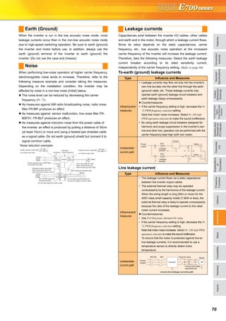
40When setting parameters, refer to the instruction manual (Applied) and understand instructions.
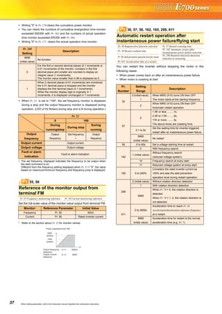
Setting of the used motor selects the thermal characteristic
appropriate for the motor.
Setting is required to use a constant-torque motor. Thermal
characteristic of the electronic thermal relay function suitable for
the motor is set.
∗1 Motor constants of Mitsubishi high efficiency motor SF-HR
∗2 Motor constants of Mitsubishi constant-torque motor SF-HRCA.
∗3 Star connection
∗4 Delta connection
For the 5.5K and 7.5K, the Pr. 0 Torque boost and Pr. 12 DC injection
brake operation voltage settings are automatically changed according
to the Pr. 71 settings as follows.
∗1 Pr. 71 setting: 0, 3 to 6, 23, 24, 40, 43, 44
∗2 Pr. 71 setting: 1, 13 to 16, 50, 53, 54
You can change the motor sound.
You can select the function that switches between forward rotation
and reverse rotation according to the analog input terminal
specifications and analog input level.
Either voltage input (0 to 5V, 0 to 10V) or current input (4 to 20mA)
can be selected for terminals 4 used for analog input.
Set the voltage/current input switch in the "V" position to select
voltage input (0 to 5V/0 to10V) and "I" position to select current input
(4 to 20mA), and change the parameter setting (Pr. 267).
( indicates main speed setting)
The time constant of the primary delay filter can be set for the
external frequency command (analog input (terminal 2, 4) signal).
Effective for filtering noise in the frequency setting circuit.
Increase the filter time constant if steady operation cannot be
performed due to noise.
A larger setting results in slower response. (The time constant
can be set between approximately 5ms to 1s with the setting of 0
to 8.)
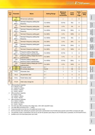
Motor selection (applied motor)
Pr. 71 Applied motor Pr. 450 Second applied motor
Pr. 71, Pr. 450
Setting
Thermal Characteristic of
the Electronic Thermal
Relay Function
Motor ( : Motor used)
Pr. 71 Pr. 450 Standard
(SF-JR, etc.)
Constant-torque
(SF-JRCA, etc.)
0
Thermal characteristics of a standard
motor (Pr. 71 initial value)
1
Thermal characteristics of the
Mitsubishi constant-torque motor
40 —
Thermal characteristic of Mitsubishi
high efficiency motor SF-HR
∗1
50 —
Thermal characteristic of Mitsubishi
constant torque motor SF-HRCA
∗2
3 — Standard
Select "Offline
auto tuning
setting"
13 — Constant-torque
23 —
Mitsubishi standard
motor SF-JR4P
(1.5kW or less)
43 —
Mitsubishi high
efficiency SF-HR
∗1
53 —
Mitsubishi constant-
torque SF-HRCA
∗2
4 — Standard
Auto tuning
data can be
read, changed,
and set.
14 — Constant-torque
24 —
Mitsubishi standard
motor SF-JR4P
(1.5kW or less)
44 —
Mitsubishi high
efficiency SF-HR
∗1
54 —
Mitsubishi constant-
torque SF-HRCA
∗2
5 — Standard∗3 Direct input of
motor
constants is
enabled
15 — Constant-torque ∗3
6 — Standard ∗4
16 — Constant-torque ∗4
— 9999 Without second applied motor (Pr. 450 initial value)
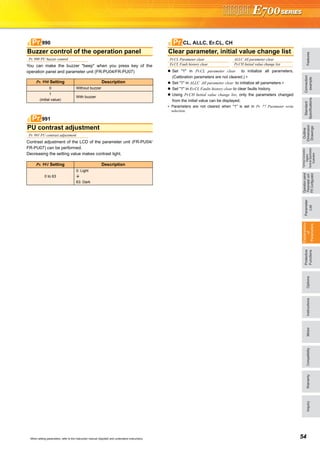
Automatic Change
Parameter
Standard Motor
Setting ∗1
Constant-torque
Motor Setting ∗2
Pr. 0 3% 2%
Pr. 12 4% 2%
71, 450Pr.
Carrier frequency and Soft-PWM
selection
Pr. 72 PWM frequency selection Pr. 240 Soft-PWM operation selection
Pr.
Number
Setting
Range
Description
72 0 to 15
PWM carrier frequency can be changed. The
setting is in [kHz].
Note that 0 indicates 0.7kHz and 15 indicates
14.5kHz.
240
0 Soft-PWM is invalid
1 When Pr. 72 = "0 to 5", Soft-PWM is valid.
Analog input selection
Pr. 73 Analog input selection Pr. 267 Terminal 4 input selection
Pr. 73
Setting
Terminal2
Input
Terminal 4 Input
Reversible
Operation
0 0 to 10V
When the AU signal is off
×
Not function1
(initial value)
0 to 5V
10 0 to 10V
Yes
11 0 to 5V
0
×
When the AU signal is on
According to Pr. 267 setting
0:4 to 20mA (initial value)
1:0 to 5V
2:0 to 10V
Not function1
(initial value)
10
× Yes
11
Response level of analog input and
noise elimination
Pr. 74 Input filter time constant
72, 240Pr.
73, 267Pr.
2.5V
C3(Pr.902)
Pr. 125
C4(Pr.903)
C2(Pr. 902)
5V
Reverse
rotation
Forward
rotation
Setfrequency(Hz)
Terminal 2
input (V)0
Frequency setting signal
Not
reversible
Reversible
74Pr.](https://image.slidesharecdn.com/catalog-fr-e700-mitsubishi-160425074315/85/Catalog-Inverter-FR-E700-Mitsubishi-Electric-Beeteco-com-38-320.jpg)
![45 When setting parameters, refer to the instruction manual (Applied) and understand instructions.
The inverter can be used to exercise process control, e.g. flow rate,
air volume or pressure.
The terminal 2 input signal or parameter setting is used as a set
point and the terminal 4 input signal used as a feedback value to
constitute a feedback system for PID control.
Pr. 128 = "20, 21" (measured value input)
Performs PID control by feedbacking the position signal of the
dancer roller, controlling the dancer roller is in the specified position.
Performs dancer control by setting 40 to 43 in Pr. 128 PID action
selection. The main speed command is the speed command of each
operation mode (external, PU, communication). Performs PID
control by the position detection signal of the dancer roller, then the
result is added to the main speed command.
You can switch the display language of the parameter unit (FR-
PU04/FR-PU07) to another.
When connecting the operation panel (PA02) of the FR-E500
series with a cable, use Pr. 146 Built-in potentiometer switching for
selecting the operation using the built-in frequency setting
potentiometer, or using [UP/DOWN] key.
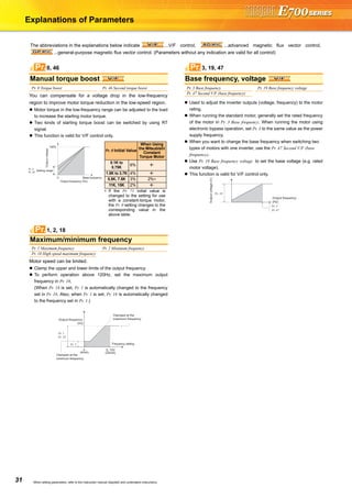
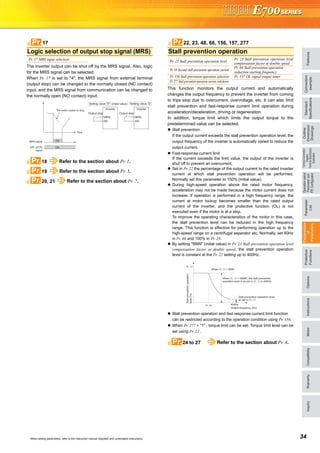
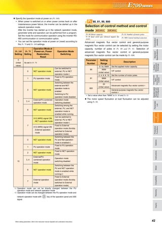
The output power during inverter running can be detected and
output to the output terminal.
(1) Output current detection
(Y12 signal, Pr. 150, Pr. 151)
The output current detection function can be used for
excessive torque detection, etc.
If the output current remains higher than the Pr. 150 setting
during inverter operation for longer than the time set in Pr.
151, the output current detection signal (Y12) is output
from the inverter's open collector or relay output terminal.
(2) Zero current detection (Y13 signal, Pr. 152, Pr. 153)
If the output current remains lower than the Pr. 152 setting
during inverter operation for longer than the time set in Pr.
153, the zero current detection (Y13) signal is output from
the inverter's open collector or relay output terminal.
PID control, dancer control
Pr. 127 PID control automatic switchover frequency Pr. 128 PID action selection
Pr. 129 PID proportional band Pr. 130 PID integral time
Pr. 131 PID upper limit Pr. 132 PID lower limit
Pr. 133 PID action set point Pr. 134 PID differential time
Parameter unit display language
selection
Pr. 145 PU display language selection
Pr. 145 Setting Description
0 (initial value) Japanese
1 English
2 German
3 French
4 Spanish
5 Italian
6 Swedish
7 Finnish
Built-in potentiometer switching
Pr. 146 Built-in potentiometer switching
Pr. 146 Setting Description
0 Built-in frequency setting potentiometer gain
1 (initial value) Digital frequency setting by the [UP/DOWN] key.
9999
Frequency setting with the built-in frequency setting
potentiometer is available when the frequency set by
[UP/DOWN] key is "0Hz".
147 Refer to the section about Pr. 7.
127 to 134Pr.
+- IM
PID operation
Pr. 133
or terminal 2
Set point
Inverter circuit
Motor
Feedback signal (measured value)
Terminal 4
Kp: Proportionality constant Ti: Integral time S: Operator Td: Differential time
Manipulated
variable
0 to 5VDC
(0 to 10VDC)
4 to 20mADC (0 to 5V, 0 to 10V)
Ti S
Kp 1+ +Td S
1
145Pr.
146Pr.
Pr.
Detection of output current (Y12 signal)
Detection of zero current (Y13 signal)
Pr. 150 Output current detection level Pr. 151 Output current detection signal delay time
Pr. 152 Zero current detection level Pr. 153 Zero current detection time
156, 157 Refer to the section about Pr. 22.
150 to 153Pr.
Time
Pr. 150
OFF ON OFFOutput current
detection signal
(Y12)
100ms
Outputcurrent
Pr. 151
OFF ON
Start signal
Time
Outputcurrent
OFF ON
Zero current
detection time
(Y13)
Pr. 153
Detection time
Pr. 153
Detection time
Pr. 152
OFF ON
0[A]
100ms*
Pr. 152
Pr.](https://image.slidesharecdn.com/catalog-fr-e700-mitsubishi-160425074315/85/Catalog-Inverter-FR-E700-Mitsubishi-Electric-Beeteco-com-43-320.jpg)
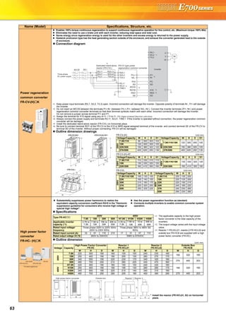
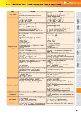
![71
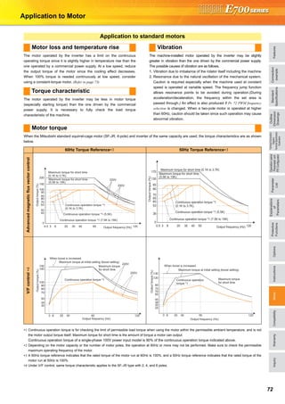
Harmonic suppression guideline
Harmonic currents flow from the inverter to a power receiving point
via a power transformer. The harmonic suppression guideline was
established to protect other consumers from these outgoing
harmonic currents.
The three-phase 200V input specifications 3.7kW or less (single-
phase 200V power input model 2.2kW or less, single-phase 100V
power input model 0.75kW) are previously covered by "Harmonic
suppression guideline for household appliances and general-
purpose products" and other models are covered by "Harmonic
suppression guideline for consumers who receive high voltage or
special high voltage". However, the transistorized inverter has
been excluded from the target products covered by "Harmonic
suppression guideline for household appliances and general-
purpose products" in January 2004 and "Harmonic suppression
guideline for household appliances and general-purpose products"
was repealed on September 6, 2004.
All capacity and all models of general-purpose inverter used by
specific consumers are covered by "Harmonic suppression
guideline for consumers who receive high voltage or special high
voltage".
"Harmonic suppression guideline for consumers who receive high
voltage or special high voltage"
This guideline sets forth the maximum values of harmonic currents
outgoing from a high-voltage or especially high-voltage consumer
who will install, add or renew harmonic generating equipment. If any
of the maximum values is exceeded, this guideline requires that
consumer to take certain suppression measures.
Users who use models other than the target models are not covered
by the guideline. However, we ask to connect an AC reactor or a DC
reactor as before to the users who are not covered by the guideline.
For compliance to the harmonic suppression guideline for
consumers who receive high voltage or special high voltage
For compliance to "Harmonic suppression guideline of the
transistorized inverter (input current of 20A or less) for consumers
other than specific consumers" published by JEMA.
Calculation of outgoing harmonic current
Input
Power
Supply
Target
Capacity
Countermeasures
Single-phase
100V
Single-phase
200V
Three-phase
200V
Three-phase
400V
All
capacities
Make a judgment based on "Harmonic
suppression guideline for consumers who
receive high voltage or special high voltage"
issued by the Japanese Ministry of Economy,
Trade and Industry (formerly Ministry of
International Trade and Industry) in
September 1994 and take measures if
necessary. For calculation method of power
supply harmonics, refer to materials below.
Reference materials
"Harmonic suppression measures of the
inverter"
Jan. 2004 Japan Electrical Manufacturer's
Association
"Calculation method of harmonic current of
the general-purpose inverter used by
specific consumers"
JEM-TR201 (revised in Dec. 2003): Japan
Electrical Manufacturer's Association
Japan Electrical Manufacturer's Association
Input
Power
Supply
Target
Capacity
Countermeasures
Single-phase
100V
0.75kW or less
Connect the AC reactor or DC reactor
recommended in a catalog or an
instruction manual.
Reference materials
"Harmonic suppression guideline of
the general-purpose inverter (input
current of 20A or less)"
JEM-TR226 (revised in Dec. 2003):
Japan Electrical Manufacturer's
Association
Single-phase
200V
2.2kW or less
Three-phase
200V
3.7kW or less
Outgoing harmonic current = fundamental wave current (value converted
from received power voltage) × operation ratio × harmonic content
Operation ratio: Operation ratio = actual load factor operation
time ratio during 30 minutes
Harmonic content: Found in Table.
Table 1: Harmonic Contents (Values at the fundamental current of 100%)
Reactor 5th 7th 11th 13th 17th 19th 23rd 25th
Three-phase
bridge
(Capacitor
smoothing)
Not used 65 41 8.5 7.7 4.3 3.1 2.6 1.8
Used
(AC side)
38 14.5 7.4 3.4 3.2 1.9 1.7 1.3
Used
(DC side)
30 13 8.4 5.0 4.7 3.2 3.0 2.2
Used
(AC, DC sides)
28 9.1 7.2 4.1 3.2 2.4 1.6 1.4
Single-phase
bridge
(Capacitor
smoothing)
Not used 50 24 5.1 4.0 1.5 1.4 - -
Used
(AC side) *
6.0 3.9 1.6 1.2 0.6 0.1 - -
∗ The harmonic contents for "single-phase bridge/with reactor" in the table 4 are
values when the reactor value is 20%. Since a 20% reactor is large and considered
to be not practical, harmonic contents when a 5% reactor is used is written in the
technical data JEM-TR201 of The Japan Electrical Manufacturers' Association and
this value is recommended for calculation for the actual practice.
Table 2: Rated Capacities and Outgoing Harmonic Currents for Three-phase
Inverter Drive
Applied
MotorkW
Rated
Current [A]
FundamentalWaveCurrent
Convertedfrom6.6kV(mA)
RatedCapacity(kVA)
Outgoing Harmonic Current Converted from
6.6kV (mA)
(No reactor, 100% operation ratio)
200V 400V 5th 7th 11th 13th 17th 19th 23rd 25th
0.4 1.61 0.81 49 0.57 31.85 20.09 4.165 3.773 2.107 1.519 1.274 0.882
0.75 2.74 1.37 83 0.97 53.95 34.03 7.055 6.391 3.569 2.573 2.158 1.494
1.5 5.50 2.75 167 1.95 108.6 68.47 14.20 12.86 7.181 5.177 4.342 3.006
2.2 7.93 3.96 240 2.81 156.0 98.40 20.40 18.48 10.32 7.440 6.240 4.320
3.7 13.0 6.50 394 4.61 257.1 161.5 33.49 30.34 16.94 12.21 10.24 7.092
5.5 19.1 9.55 579 6.77 376.1 237.4 49.22 44.58 24.90 17.95 15.05 10.42
7.5 25.6 12.8 776 9.07 504.4 318.2 65.96 59.75 33.37 24.06 20.18 13.97
11 36.9 18.5 1121 13.1 728.7 459.6 95.29 86.32 48.20 34.75 29.15 20.18
15 49.8 24.9 1509 17.6 980.9 618.7 128.3 116.2 64.89 46.78 39.24 27.16](https://image.slidesharecdn.com/catalog-fr-e700-mitsubishi-160425074315/85/Catalog-Inverter-FR-E700-Mitsubishi-Electric-Beeteco-com-69-320.jpg)
![77
Warranty
1. Gratis warranty period and coverage
[Gratis warranty period]
Note that an installation period of less than one year after installation in your company or your customer's premises or a
period of less than18 months (counted from the date of production) after shipment from our company, whichever is shorter,
is selected.
[Coverage]
(1) Diagnosis of failure
As a general rule, diagnosis of failure is done on site by the customer.
However, Mitsubishi or Mitsubishi service network can perform this service for an agreed upon fee upon the customer's
request.
There will be no charges if the cause of the breakdown is found to be the fault of Mitsubishi.
(2) Breakdown repairs
There will be a charge for breakdown repairs, exchange replacements and on site visits for the following four conditions
even in gratis warranty period, otherwise there will be no charge.
1)Breakdowns due to improper storage, handling, careless accident, software or hardware design by the customer.
2)Breakdowns due to modifications of the product without the consent of the manufacturer.
3)Breakdowns resulting from using the product outside the specified specifications of the product.
4)Breakdowns that are outside the terms of warranty.
Since the above services are limited to Japan, diagnosis of failures, etc. are not performed abroad.
If you desire the after service abroad, please register with Mitsubishi. For details, consult us in advance.
2. Exclusion of opportunity loss from warranty liability
Regardless of the gratis warranty term, compensation to opportunity losses incurred to your company or your customers by
failures of Mitsubishi products and compensation for damages to products other than Mitsubishi products and other
services are not covered under warranty.
3. Repair period after production is discontinued
Mitsubishi shall accept product repairs for seven years after production of the product is discontinued.
4. Terms of delivery
In regard to the standard product, Mitsubishi shall deliver the standard product without application settings or adjustments
to the customer and Mitsubishi is not liable for on site adjustment or test run of the product.](https://image.slidesharecdn.com/catalog-fr-e700-mitsubishi-160425074315/85/Catalog-Inverter-FR-E700-Mitsubishi-Electric-Beeteco-com-75-320.jpg)


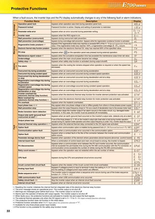
The document provides detailed specifications and features of Mitsubishi inverters, including their expandability, compact design, and long-life components. It covers operational functions, safety features, compatibility, and various plug-in options for enhanced functionality. Additionally, it emphasizes the inverters' environmental compliance and maintenance-friendly design, catering to diverse applications and requirements.


