This article tells about what is an Opto electronic oscillator, working of the oscillator, multi-loop Opto-electronic oscillator, and its applications.
Introduction
Silicon for the smarts, but stomach acid for the power
Painless diabetes testing drug delivery and more
Function
Advantages
Disadvantages
Conclusion
Reference
This is a brief introduction to MicroLED also known as micro-LED, mLED or µLED, which is a latest self-emitting display technology that shares many traits with OLED. MicroLED has the potential to take on and outperform OLED, but it won’t completely displace OLED and LCD. Here we discuss the basic structure, differences with OLED and LCD. What are the major challenges? Advantages and Disadvantages, Application and the Future of MicroLED.
this ppt was created by me and i hope it helps to all of you out there. peace
objective : school projects
personal reference
teachers reference
i know its a bit lengthy but im 100% sure it will be helpful
plz leave a like
thxs
Wearable Computing and Human Computer InterfacesJeffrey Funk
These slides discuss how improvements in ICs, MEMS, cameras, and other electronic components are making wearable computing and new forms of human-computer interfaces economically feasible. Improvements in digital signal processing ICs and MEMS-based microphones are rapidly improving the technical and economical feasibility of voice-recognition based interfaces. Improvements in 2D and 3D image sensors (e.g., camera ICs) are rapidly improving the technical and economical feasibility of gesture-based interfaces, augmented reality, and virtual reality. Improvements in ICs, MEMS, displays and other components are rapidly making many forms of wearable computing economically feasible; these include many forms of head, arm, torso, and leg-mounted displays. Improvements in the materials for both non-invasive and invasive brain scans are rapidly improving the technical and economical feasibility of neural interfaces.
Introducing higher dielectric constant (k > 10) insulators [mainly transition metal (TM) oxides] is therefore indispensable for the 70 nm technology node and beyond
TM silicates such as HfSiOx have been preferred because they have better thermal stability compared to their oxides. The dielectric constant of TM silicates is less than TM oxides but higher than silicon oxide.
Fabrication of Thermo Electric Solar Fridgeiosrjce
IOSR Journal of Mechanical and Civil Engineering (IOSR-JMCE) is a double blind peer reviewed International Journal that provides rapid publication (within a month) of articles in all areas of mechanical and civil engineering and its applications. The journal welcomes publications of high quality papers on theoretical developments and practical applications in mechanical and civil engineering. Original research papers, state-of-the-art reviews, and high quality technical notes are invited for publications.
Advantages of electrical heating, Heating methods,
Resistance heating – direct and indirect resistance heating, properties of resistance heating elements
Induction heating; principle of core type and coreless induction furnace
Electric arc heating, direct and indirect arc heating
Microwave heating
Dielectric heating
Similar to Electric heating uee nee802 unit 1 (20)
Explore the innovative world of trenchless pipe repair with our comprehensive guide, "The Benefits and Techniques of Trenchless Pipe Repair." This document delves into the modern methods of repairing underground pipes without the need for extensive excavation, highlighting the numerous advantages and the latest techniques used in the industry.
Learn about the cost savings, reduced environmental impact, and minimal disruption associated with trenchless technology. Discover detailed explanations of popular techniques such as pipe bursting, cured-in-place pipe (CIPP) lining, and directional drilling. Understand how these methods can be applied to various types of infrastructure, from residential plumbing to large-scale municipal systems.
Ideal for homeowners, contractors, engineers, and anyone interested in modern plumbing solutions, this guide provides valuable insights into why trenchless pipe repair is becoming the preferred choice for pipe rehabilitation. Stay informed about the latest advancements and best practices in the field.
Overview of the fundamental roles in Hydropower generation and the components involved in wider Electrical Engineering.
This paper presents the design and construction of hydroelectric dams from the hydrologist’s survey of the valley before construction, all aspects and involved disciplines, fluid dynamics, structural engineering, generation and mains frequency regulation to the very transmission of power through the network in the United Kingdom.
Author: Robbie Edward Sayers
Collaborators and co editors: Charlie Sims and Connor Healey.
(C) 2024 Robbie E. Sayers
Cosmetic shop management system project report.pdfKamal Acharya
Buying new cosmetic products is difficult. It can even be scary for those who have sensitive skin and are prone to skin trouble. The information needed to alleviate this problem is on the back of each product, but it's thought to interpret those ingredient lists unless you have a background in chemistry.
Instead of buying and hoping for the best, we can use data science to help us predict which products may be good fits for us. It includes various function programs to do the above mentioned tasks.
Data file handling has been effectively used in the program.
The automated cosmetic shop management system should deal with the automation of general workflow and administration process of the shop. The main processes of the system focus on customer's request where the system is able to search the most appropriate products and deliver it to the customers. It should help the employees to quickly identify the list of cosmetic product that have reached the minimum quantity and also keep a track of expired date for each cosmetic product. It should help the employees to find the rack number in which the product is placed.It is also Faster and more efficient way.
Immunizing Image Classifiers Against Localized Adversary Attacksgerogepatton
This paper addresses the vulnerability of deep learning models, particularly convolutional neural networks
(CNN)s, to adversarial attacks and presents a proactive training technique designed to counter them. We
introduce a novel volumization algorithm, which transforms 2D images into 3D volumetric representations.
When combined with 3D convolution and deep curriculum learning optimization (CLO), itsignificantly improves
the immunity of models against localized universal attacks by up to 40%. We evaluate our proposed approach
using contemporary CNN architectures and the modified Canadian Institute for Advanced Research (CIFAR-10
and CIFAR-100) and ImageNet Large Scale Visual Recognition Challenge (ILSVRC12) datasets, showcasing
accuracy improvements over previous techniques. The results indicate that the combination of the volumetric
input and curriculum learning holds significant promise for mitigating adversarial attacks without necessitating
adversary training.
Water scarcity is the lack of fresh water resources to meet the standard water demand. There are two type of water scarcity. One is physical. The other is economic water scarcity.
CFD Simulation of By-pass Flow in a HRSG module by R&R Consult.pptxR&R Consult
CFD analysis is incredibly effective at solving mysteries and improving the performance of complex systems!
Here's a great example: At a large natural gas-fired power plant, where they use waste heat to generate steam and energy, they were puzzled that their boiler wasn't producing as much steam as expected.
R&R and Tetra Engineering Group Inc. were asked to solve the issue with reduced steam production.
An inspection had shown that a significant amount of hot flue gas was bypassing the boiler tubes, where the heat was supposed to be transferred.
R&R Consult conducted a CFD analysis, which revealed that 6.3% of the flue gas was bypassing the boiler tubes without transferring heat. The analysis also showed that the flue gas was instead being directed along the sides of the boiler and between the modules that were supposed to capture the heat. This was the cause of the reduced performance.
Based on our results, Tetra Engineering installed covering plates to reduce the bypass flow. This improved the boiler's performance and increased electricity production.
It is always satisfying when we can help solve complex challenges like this. Do your systems also need a check-up or optimization? Give us a call!
Work done in cooperation with James Malloy and David Moelling from Tetra Engineering.
More examples of our work https://www.r-r-consult.dk/en/cases-en/
Final project report on grocery store management system..pdfKamal Acharya
In today’s fast-changing business environment, it’s extremely important to be able to respond to client needs in the most effective and timely manner. If your customers wish to see your business online and have instant access to your products or services.
Online Grocery Store is an e-commerce website, which retails various grocery products. This project allows viewing various products available enables registered users to purchase desired products instantly using Paytm, UPI payment processor (Instant Pay) and also can place order by using Cash on Delivery (Pay Later) option. This project provides an easy access to Administrators and Managers to view orders placed using Pay Later and Instant Pay options.
In order to develop an e-commerce website, a number of Technologies must be studied and understood. These include multi-tiered architecture, server and client-side scripting techniques, implementation technologies, programming language (such as PHP, HTML, CSS, JavaScript) and MySQL relational databases. This is a project with the objective to develop a basic website where a consumer is provided with a shopping cart website and also to know about the technologies used to develop such a website.
This document will discuss each of the underlying technologies to create and implement an e- commerce website.
Industrial Training at Shahjalal Fertilizer Company Limited (SFCL)MdTanvirMahtab2
This presentation is about the working procedure of Shahjalal Fertilizer Company Limited (SFCL). A Govt. owned Company of Bangladesh Chemical Industries Corporation under Ministry of Industries.
Saudi Arabia stands as a titan in the global energy landscape, renowned for its abundant oil and gas resources. It's the largest exporter of petroleum and holds some of the world's most significant reserves. Let's delve into the top 10 oil and gas projects shaping Saudi Arabia's energy future in 2024.
Top 10 Oil and Gas Projects in Saudi Arabia 2024.pdf
Electric heating uee nee802 unit 1
1. Electric Heating
I) Advantages of Electrically produced heat:
Some of the most important advantages of electrically produced heat are:
i. Cleanliness- The complete elimination of dust and ash keeps cleaning costs down to a
minimum.
ii. Absence of flue gases: No space has to be used in providing flues and there is no risk of
contamination of the atmosphere or of the objects being heated.
iii. Ease of Control-Simple and accurate control of temperature can be provided either by hand or
by fully automatic devices, so that temperature can be maintained constant or made to vary in
accordance with a predetermined plan. Further any particular temperature or temperature cycle
can be accurately repeated at any time.
iv. Low attention and maintenance costs- Electric heating equipment in general requires no
attention, while maintenance costs are negligibly small. This results in considerable savings in
labour costs over alternative heating systems.
v. Special heating requirements- special heating requirements such as uniform heating or heating
one particular portion of a job without affecting the other parts or heating with no oxidation is
met only by electric heating.
vi. Higher efficiency- Heat produced electrically does not go away waste through the chimney or
other products. Most of the heat produced is utilized for heating the material.
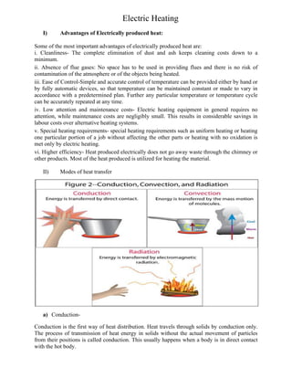
II) Modes of heat transfer
a) Conduction-
Conduction is the first way of heat distribution. Heat travels through solids by conduction only.
The process of transmission of heat energy in solids without the actual movement of particles
from their positions is called conduction. This usually happens when a body is in direct contact
with the hot body.
2. b) Convection-
Convection takes place in liquids and gases only as the particles are free to move. The
phenomenon due to which particles of a medium actually move to the source of heat
energy and on absorbing heat energy, move away from it thereby making space for other
particles to move to the source of heat energy is called convection. One natural
application of convection is the occurrence of land breeze and sea breeze.
During the day, the air above the land gets heated very quickly and becomes lighter as air
expands on heating. This air rises and makes place for the cool breeze that is above water.
This phenomenon is called sea breeze.
When the water of the sea is finally hot at the end of the day and thus the air above it is
hotter too, the air above the land is cool. This hot air above the sea rises, causing the cool
air from above the land to take its place. This phenomenon is called land breeze.
c) Radiation:
The last method of transfer is radiation. The transference of heat energy from a hot body
to a cold body directly, without heating the space in between the two bodies, is called
radiation. As a matter of fact, radiation requires no medium. For e.g. the vast space
between the earth and the sun is a vacuum; yet the heat of the sun reaches earth.
Classification of electric heating methods
Electric resistance heating is defined as “the heat produced by passing an electric current through
a material that preferably has high resistance.” As the current passes through the material, ohmic
losses (I2
R losses) occur. These losses cause the conversion of electrical energy into heat.
3. There are two methods of electric resistance heating:
Direct electric resistance heating
In direct electric resistance heating, the current is passed directly through the material that has to
be heated, for example, resistance welding & electrodes for water heating boiler.
Construction:
In case of DC or single phase Ac two electrodes are required, but there will be three electrodes in
case of three phase supply. In this method in the charge (Resistive material) is put in the Tank.
The electrodes are immersed in the charge at the same time the electric connected with the
electrodes. The charge should be in a powder, Pieces or Liquid. If the charge is not in the Type
means it requires high resistive heating element.
The Heating Element to be used in furnace should possess the following Properties.
(i)High Resistivity: This will reduce the length of the heating element,
(ii) High Melting Point: It is necessary for obtaining high temperature,
(iii) Free from oxidation: The element material should not be oxidized when subjected to high
temperature.
(iv)Low temperature co-efficient: For accurate temperature control the resistance should be
nearly constant at all temperatures. This can be obtained only if the resistance of the material of
the element does not change appreciably.
In-Direct Resistance heating Method.
In this Process electric Current is passed through a resistive element and heat thus produced is
conveyed to the substances to be heated by convection or radiation Process. Resistance Oven,
Immersion heaters are applications of this method. The arrangement is shown in the Fig1.2.
In this method the charge and the electrodes are separated and in between the charges the heating
material is fixed and the electrodes are connected with the corresponding supply.(AC or DC).The
Heating Element is selected through the important properties like high Resistivity, High Melting
point, Low Temperature Coefficient and Free From Oxidation.
4. Operation: The supply is given through the electrodes. The charge should be in the form of
powder or liquid. If the charge is metal pieces means the powder of lightly resistive material is
sprinkled over the surface of the charge because of short circuit. The current is allowed to pass
through the charge which heats up according to the Joules Law. Then the heat transferred
through the heat waves (Radiation).So it requires high power to heat the material compare with
the direct resistance heating Method. As the current in this case is not easily variable, therefore
automatic temperature control is not possible.
Electric Arc Heating
Arc heating
The heating of matter by an electric arc. The matter may be solid, liquid, or gaseous.
When a high voltage is applied across an air gap, the air in the gap gets ionized under the
influence of electrostatic forces and become conducting medium. Current flows in the form of a
continuous spark , called the arc.
It is to be noted that a very high voltage is required to establish an arc across an air gap but to
maintain an arc small voltage may be sufficient.
Arc drawn between two electrodes produces heat and has a temperature between 1,000 C and
35000 C depending on the material of the electrodes used.
When the heating is direct, the materialto be heated is one electrode; for indirect heating, the heat
is transferred from the arc by conduction, convection, or radiation.
Electric Arc furnaces
Electric Arc Furnace means an extremely hot enclosed space, where heat is produced by means
of electrical arcing for melting certain metals such as scrap steel without changing electro-
chemical properties of the metal.
Here, electric arc is produced between the electrodes. This electric arc is used for melting the
metal. The electric furnace is in form of a vertical vessel of fire brick. There are mainly two
types of electric furnaces. They are alternating current (AC) and direct current (DC) operated
electric furnaces.
DC Electric Arc Furnace
DC Arc Furnace is recent and advanced furnace compared to AC Arc Furnace. In DC Arc
Furnace current flows from cathode to anode. This furnace has only a single graphite electrode
and the other electrode is embedded at the bottom of the furnace. There are different methods for
fixing anode at the bottom of the DC furnace.
The first arrangement consists of a single metal anode placed at the bottom. It is water cooled
because it gets heated up fast. In the next one, the anode be the conducting hearth by C-MgO
lining. The current is given to the Cu plate positioned at the bottom portion. Here, the cooling of
anode is by the air. In the third arrangement, the metal rods act as anode. It is entrenched in MgO
mass. In the fourth arrangement, the anode is the thin sheets. The sheets are entrenched in MgO
mass.
Advantages of DC Electric Arc Furnace
• Decrease in electrode consumption by 50%.
• Melting is almost uniform.
• Decrease in power consumption (5 to 10%).
• Decrease in flicker by 50%.
• Decrease in refractory consumption
5. • Hearth life can be extended.
AC electric Arc Furnace
In AC electric furnace, current flows between the electrodes through the charges in metal. In this
furnace three graphite electrodes are used as cathode. The scrap itself acts as an anode. When
compared to DC arc furnace, this is cost effective. This furnace is most commonly used in small
furnaces.
Construction of Electric Arc Furnace
As mentioned above, the electric furnace is a large firebrick lined erect vessel. It is demonstrated
in figure 2.
The main parts of electric furnace are the roof, hearth (lower part of a furnace, from where
molten metal is collected), electrodes, and side walls. The roof consists of three holes through
which the electrodes are inserted. The roof is made up of alumina and magnesite-chromite
bricks. The hearth includes metal and slag. The tilting mechanism is used to pour the metal that
6. is molten to the cradle by shifting the furnace. For the electrode removal and furnace charging
(topping up scrap metals), roof retraction mechanism is incorporated. The provision for fume
extraction is also given around the furnace considering the health of operators. In AC electric
furnace, electrodes are three in number. These are round in section. Graphite is used as
electrodes because of high electric conductivity. Carbon electrodes are also used. The electrodes
positioning system helps to raise and lower the electrodes automatically. The electrodes get
highly oxidized when the current density is high.
Transformer: –
The transformer provides the electrical supply to the electrodes. It is located near to the furnace.
It is well protected. The rating of large electric arc furnace may be up to 60MVA.
Working Principle of Electrical Arc Furnace
The working of electric furnace includes charging the electrode, meltdown period (melting the
metal) and refining. The heavy and light scrap in the large basket is preheated with the help of
exhaust gas. For speeding up the slag formation, burnt lime and spar are added to it. The
charging of furnace takes place by swinging the roof of the furnace. As per requirement, the hot
metal charging also takes place.
Next is the meltdown period. The electrodes are moved down onto the scrap in this period. Then
the arc is produced between the electrode and metal. By considering the protection aspect, low
voltage is selected for this. After the arc is shielded by electrodes, the voltage is increased for
speeding up the melting process. In this process, carbon, silicon, and manganese get oxidized.
The lower current is required for large arc production. The heat loss is also less in this. Melting
down process can be fastening by deep bathing of electrodes.
Refining process starts during melting. The removal of sulfur is not essential for single oxidizing
slag practice. Only phosphorous removal is required in this. But in double slag practice, both (S
and P) are to be removed. After the deoxidizing; in double slag practice, the removal of oxidizing
slag is performed. Next, with the help of aluminum or ferromanganese or ferrosilicon, it gets
deoxidized. When the bathing chemistry and required temperature is reached, the heat will get
deoxidized. Then, the molten metal is ready for tapping.
For the cooling of the furnace, tubular pressure panels or hollow annulus spraying can be used.
Electrodes:
The electrodes used in the arc furnaces are of three types
a) Carbon electrodes
b) Graphite electrodes
c) Self-baking electrodes
Materials of electrodes namely carbon and graphite has been selected on account of their
electrical conductivity , insolubility, chemical inertness, mechanical strength and resistance to
thermal stock.
With graphite or carbon electrode, the temperature obtainable from the arc is between 3000 C to
3500 C.
Induction heating
Induction heating is the process of heating an electrically conducting object (usually a metal) by
electromagnetic induction, through heat generated in the object by eddy currents.
Simply stated, induction heating is the most clean, efficient, cost-effective, precise, and
repeatable method of material heating available to the industry, today.
7. Induction heating takes place in an electrically conducting object (not necessarily magnetic steel)
when the object is placed in a varying magnetic field. Induction heating is due to the hysteresis
and eddy-current losses.
The purpose of induction heating may be to harden a part to prevent wear; make the metal plastic
for forging or hot-forming into a desired shape; braze or solder two parts together; melt and mix
the ingredients which go into the high-temperature alloys, making jet engines possible; or for any
number of other applications.
The Basics
Induction heating takes place in an electrically conducting object (not necessarily magnetic steel) when the
object is placed in a varying magnetic field. Induction heating is due to the hysteresis and eddy-current
losses.
Hysteresis losses only occur in magnetic materials such as steel, nickel, and very few others. Hysteresis
loss states that this is caused by friction between molecules when the material is magnetized first in one
direction, and then in the other. The molecules may be regarded as small magnets which turn around with
each reversal of direction of the magnetic field. Work (energy) is required to turn them around. The energy
converts into heat. The rate of expenditure of energy (power) increases with an increased rate of reversal
(frequency).
Eddy-current losses occur in any conducting material in a varying magnetic field. This causes heating, even
if the materials do not have any of the magnetic properties usually associated with iron and steel. Examples
are copper, brass, aluminum, zirconium, nonmagnetic stainless steel, and uranium. Eddy currents are
electric currents inducted by transformer action in the material. As their name implies, they appear to flow
around in swirls on eddies within a solid mass of material. Eddy-current losses are much more important
than hysteresis losses in induction heating. Note that induction heating is applied to nonmagnetic materials,
where no hysteresis losses occur.
For the heating of steel for hardening, forging, melting, or any other purposes which require a temperature
above Curie temperature, we cannot depend upon hysteresis. Steel loses its magnetic properties above this
temperature. When steel is heated below the Curie point, the contribution of hysteresis is usually so small
that it can be ignored. For all practical purposes, the I2
R of the eddy currents is the only way in which
electrical energy can be turned into heat for induction heating purposes.
Two basic things for induction heating to occur:
• A changing magnetic field
8. • An electrically conductive material placed into the magnetic field
Advantages of Induction Heating
Induction heating is particularly useful where highly repetitive operations are performed. Once an
induction heating machine is properly adjusted, part after part is heated with identical results. The ability of
induction heating to heat successive parts identically means that the process is adaptable to completely
automatic operation, where the work pieces are loaded and unloaded mechanically.
Induction heating has made it possible to locate operations, such as hardening, in production lines along
with other machine tools instead of in remote, separate departments. This saves the time of transporting the
parts from one part of the factory to another. Induction heating is clean. It does not throw off unpleasant
heat. Working conditions around induction heating machines are good. They do not give off the smoke and
dirt which are sometimes associated with heat-treating departments and forge shops.
Another desirable characteristic of induction heating is its ability to heat only a small portion of a work
piece, offering advantages where it is unnecessary to heat the whole part. This advantage is critical in
essential parts with a few localized high-wear areas during normal operation. Previously, a higher quality,
more expensive material would be required to withstand the wear of operation. With induction, less
expensive materials can be locally processed to achieve the durability required.
Induction heating is fast. A properly tuned induction heating machine can process high part volumes per
minute by utilizing efficient coil design and part handling. Since induction heating machines are well suited
to automation, they can easily integrate with existing part production lines. Unlike radiant heating
solutions, induction heating heats only the part inside the coil without wasting energy on unnecessary
heating.
Induction heating is clean. Without flame operations that leave soot or otherwise require cleaning after
heating, induction is a choice for parts that require clean heating, such as in brazing operations. Because
induction heating utilizes magnetic fields that are permeable through glass or other materials, controlled
atmosphere heating through induction is a possibility.
ELECTRIC INDUCTION FURNACE
The electric induction furnace is a type of melting furnace that uses electric currents to
melt metal. Induction furnaces are ideal for melting and alloying a wide variety of metals
with minimum melt losses, however, little refining of the metal is possible.
PRINCIPLE OF INDUCTION FURNACE: The principle of induction furnace is the
Induction heating
INDUCTION HEATING: Induction heating is a form of non-contact heating for
conducting material.
2) JOULE HEATING Joule heating, also known as ohmic heating and resistive heating,
is the process by which the passage of an electric current through a conductor releases
heat. The heat produced is proportional to the square of the current multiplied by the
electrical resistance of the wire.
Since heat is transferred to the product via electromagnetic waves, the part never comes
into direct contact with any flame, the inductor itself does not get hot and there is no
product contamination.
Induction heating is a rapid, clean, non-polluting heating.
The induction coil is cool to the touch; the heat that builds up in the coil is constantly
cooled with circulating water.
9. FEATURES OF INDUCTION FURNACE
An electric induction furnace requires an electric coil to produce the charge. This heating
coil is eventually replaced. The crucible in which the metal is placed is made of stronger
materials that can resist the required heat, and the electric coil itself cooled by a water
system so that it does not overheat or melt. The induction furnace can range in size, from
a small furnace used for very precise alloys only about a kilogram in weight to a much
larger furnaces made to mass produce clean metal for many different applications. The
advantage of the induction furnace is a clean, energy-efficient and well controllable
melting process compared to most other means of metal melting. foundries use this
type of furnace and now also more iron foundries are replacing cupolas with induction
furnaces to melt cast iron, as the former emit lots of dust and other pollutants. Induction
furnace capacities range from less than one kilogram to one hundred tonnes capacity,
and are used to melt iron and steel, copper, aluminium, and precious metals. The one
major drawback to induction furnace usage in a foundry is the lack of refining capacity;
charge materials must be clean of oxidation products and of a known composition, and
some alloying elements may be lost due to oxidation (and must be re-added to the melt).
CONSTRUCTION OF INDUCTION FURNACE There are many different designs
for the electric induction furnace, but they all center around a basic idea. The electrical
coil is placed around or inside of the crucible, which holds the metal to be melted.
Often this crucible is divided into two different parts. The lower section holds the melt in
its purest form, the metal as the manufacturers desire it, while the higher section is used
to remove the slag, or the contaminants that rise to the surface of the melt. Crucibles may
also be equipped with strong lids to lessen how much air has access to the melting
metal until it is poured out, making a purer melt.
TYPES OF INDUCTION FURNACE
There are two main types of induction furnace: coreless and channel.
Coreless induction furnaces.
10. The heart of the coreless induction furnace is the coil, which consists of a hollow
section of heavy duty, high conductivity copper tubing which is wound into a helical coil.
Coil shape is contained within a steel shell. To protect it from overheating, the coil is
water-cooled, the water being recirculated and cooled in a cooling tower. The crucible
is formed by ramming a granular refractory between the coil and a hollow internal.
The coreless induction furnace is commonly used to melt all grades of steels and irons
as well as many non-ferrous alloys. The furnace is ideal for remelting and alloying
because of the high degree of control over temperature and chemistry while the induction
current provides good circulation of the melt.
Channel type or Core type induction furnaces
The direct core type induction furnace is a low frequency core type electrical heating
furnace used to melt metals. The furnace is similar to that of a transformer in which the
primary circuit is a winding for electrical supply and the secondary circuit is a single turn
circular hearth which contains the charge to be heated. The two are magnetically coupled
but poorly coupled one another by an iron core. The heating furnace is in the form of a
trough which contains the charge to be melted in the form of an annular ring. Melting is
rapid in this type of furnace and also the accurate control of temperature can be achieved.
Since poor coupling results in high leakage reactance and poor power factor, the furnace
is operated at very low frequencies in the order of 10 Hz
Advantages of Direct Core Type Induction Furnace
1. Rapid melting.
2. Accurate control of the temperature.
3. Clean heating.
4. The furnace inherently has stirring action of the molten material and this result in
uniform end material.
Disadvantages of Direct Core Type Induction Furnace
1. Pinch effect – at high current densities the current flowing through the melt will
interact with magnetic field of the core and can constrict the cross-section of the molten
metal resulting in complete interruption of the secondary circuit.
11. 2. The furnace cannot be started with a solid material as it may open circuit the
secondary and requires some molten material to be started but the additional metal can be
added once the furnace is heated up.
3. The furnace is not suitable for intermittent operation since it always requires the
molten material.
ADVANTAGES OF INDUCTION FURNACE:
Induction furnaces offer certain advantages over other furnace systems. They include:
1. Higher Yield. The absence of combustion sources reduces oxidation losses that can
be significant in production economics.
2. Faster Startup. Full power from the power supply is available, instantaneously, thus
reducing the time to reach working temperature. Cold charge-to-tap times of one to
two hours are common.
3. Flexibility. No molten metal is necessary to start medium frequency coreless
induction melting equipment. This facilitates repeated cold starting and frequent alloy
changes.
4. Natural Stirring. Medium frequency units can give a strong stirring action resulting in
a homogeneous melt.
5. Cleaner Melting. No by-products of combustion means a cleaner melting
environment and no associated products of combustion pollution control systems.
6. Compact Installation. High melting rates can be obtained from small furnaces.
7. Reduced Refractory. The compact size in relation to melting rate means induction
furnaces require much less refractory than fuel-fired units
8. Better Working Environment. Induction furnaces are much quieter than gas furnaces,
arc furnaces, or cupolas. No combustion gas is present and waste heat is minimized.
9. Energy Conservation. Overall energy efficiency in induction melting ranges from 55
to 75 percent, and is significantly better than combustion processes.
DISADVANTAGES OF INDUCTION FURNACE
1. Refining in Induction Furnace is not as intensive or effective as in Electric Arc Furnace
(EAF).
2. Life of Refractory lining is low as compared to EAF.
3. Removal of S & P is limited, so selection of charges with less impurity is required.
Dielectric heating
Dielectric heating, also known as electronic heating, RF (radio frequency) heating, and
high-frequency heating, is the process in which a radio frequency alternating electric
field, or radio wave or microwave electromagnetic radiation heats a dielectric material.
At higher frequencies, this heating is caused by molecular dipole rotation within the
dielectric
Dielectric heating, also called Capacitance Heating, method by which the temperature of an
electrically non-conducting (insulating) material can be raised by subjecting the material to a
high-frequency electromagnetic field. The method is widely employed industrially for heating
thermosetting glues, for drying lumber and other fibrous materials, for preheating plastics before
molding, and for fast jelling and drying of foam rubber.
The material to be heated is placed between two metal plates, called electrodes, to which a
source of high-frequency energy is connected. The resultant heating, in homogeneous materials,
occurs throughout the material.
12. Figure 1: Principle of radio frequency heating
Meaning of Dielectric Heating:
When non-metallic parts such as wood, plastics, bones are subjected to an alternating
electrostatic field dielectric loss occurs. In dielectric heating use of these losses is made. The
material to be heated is placed as a slab between metallic plates or electrodes connected to high
frequency ac supply. For producing sufficient heat frequency between 10 and 30 MHz is used.
Even though voltage up to 20 kV have been used but from personnel safety point of view
voltages between 600 V and 3 kV are in common use. The necessary high-frequency supply is
obtained from a valve oscillator, as in the case of high frequency eddy current heating. An
overall efficiency is about 50%.
The current drawn by the capacitor, when an ac supply voltage is applied across its two plates,
does not lead the supply voltage by exactly 90° and there is always an in-phase component of the
current. Due to this in-phase (or active) component of current, heat is always produced in the
dielectric material placed in between the two plates of the capacitor.
The electric energy dissipated in the form of heat energy in the dielectric material is known as
dielectric loss. The dielectric loss is directly proportional to the frequency of ac supply given to
the two plates of the capacitor. The physical conception of the dielectric loss is just as a
molecular friction in the dielectric material when an ac electrostatic field is applied to it.
Insulators being poor conductors cannot be heated up quickly from outside. In dielectric heating
the heat is produced within the material itself. Because heat generation is uniform, the dielectric
material is heated uniformly. This is the important property of dielectric heating.
In insulators or non-conducting materials, the amount of heat produced by dielectric heating can
be calculated as follows:
The material to be heated may be considered as the imperfect dielectric of a condenser and may
be, therefore, represented as a capacitance placed in parallel with a resistance, as shown in Fig.
5.20 (b). The phasor diagram of the circuit is shown in Fig. 5.20 (c). If V is supply voltage in
volts, f is supply frequency in Hz, C is the capacitance of the condenser in farads and cos φ is
power factor of the load or charge,
13. Current through the capacitor,
Where C is in farads and V is in volts. The current drawn from supply-
The value of power factor for a particular non-conducting material is constant, and the capacity
is determined from the dimensions of plates, the charge which serves as the dielectric medium
and the dielectric constant. Therefore, the dielectric heating depends upon the values of the
frequency and the voltage. By varying one of these two quantities, the rate of dielectric heating
can be varied. The insulation problem limits the voltage to be used; hence to achieve more heat,
high frequency is used. However, there is a limit also, on the high frequency, imposed by cost
involved in getting a circuit for obtaining very high frequencies and other difficulties.
The capacity of the condenser can be calculated from the following relation-
Where, ϵr is relative permittivity of dielectric, ϵ0 is absolute permittivity of vacuum and equals
8.854 x 10⁻¹²
F/m, t is the thickness of dielectric in meters and A is the surface area of plates in
m2
.
Advantages of Dielectric Heating:
(i) If the material to be heated is homogeneous, and the alternating (or varying) electric field is
uniform, heat is developed uniformly and simultaneously throughout the entire mass of the
charge.
(ii) As materials heated by this process are non-conducting, so by other methods heat cannot be
conducted to inside so easily.
Applications of Dielectric Heating:
The cost of the equipment required for dielectric heating is so high that it is employed only
where other methods are impracticable or too slow.
14. Some of the applications of dielectric heating are given below:
1. Preheating of Plastic Preforms:
The raw material in the form of tablets or biscuits, commonly called plastic preforms, is required
to be heated uniformly before putting them into the hot moulds so that whole mass becomes fluid
at a time, otherwise if the raw material is put directly into the moulds, usually heated by steam,
the outer skin of the preforms will become hot and start curing while the core of the material has
not reached fluid temperature resulting in unequal hardening of the plastic and improper filling
of moulds corners.
Difficulty arises due to the fact that plastic raw material once cured cannot be softened again
satisfactorily. Any method of heating depending upon conduction of heat from surface to the
core would miserably fail because plastic is bad conductor of heat. Dielectric heating is the only
method which can be used for preheating of plastic preforms to proper temperature uniformly.
2. Gluing of Wood:
Dielectric heating is most commonly used for gluing of wooden sheets or boards as in this
method of gluing the moisture contents of the wooden sheets remain unaltered. It is due to the
fact that heat can be applied to the desired surface. Main difficulty in using animal glues is of
long curing time and that parts to be joined are to be kept under mechanical pressure after
application of glue for a period of about 24 hours. Mechanical pressure may be applied in gluing
of wood by dielectric heating in order to secure better adhesion. Because of higher loss factor of
glue as compared to that of wood most of the heat developed goes into the glue and very little
heat is wasted.
High frequency dielectric heating is very economical for obtaining curved wood sections such as
furniture. The curves obtained by this method are stable.
3. Baking of Foundary Cores:
In foundaries resin type thermosetting binders are employed as they set almost instantaneously
when brought to polymerizing temperature. The dielectric heating evaporates water rapidly from
the core mix and at the same time raises the temperature of the core material to polymerization
point. Hence dielectric heating is most suitable for baking foundary cores mixed with
thermosetting resin type core binders.
4. Diathermy:
Dielectric heating is also employed for heating tissues and bones of the body required for the
treatment of certain types of pains and diseases.
5. Sterlization:
The dielectric heating is quite suitable for sterilization of bandages, absorbent cotton, sterile
gauge, instruments etc.
6. Textile Industry:
In textile industry the dielectric heating is employed for drying purposes.
15. 7. Electronic Sewing:
Nowadays rain coats, umbrellas, food containers, medicine containers etc. are made from plastic
film materials. In case of ordinary stitching by thread they will be no longer water tight and also
become weak at seam. With adhesives curing times will be longer. In case of electronic sewing
the films to be stitched are rolled in between cold rollers to which radio-frequency voltage is
applied. The heat produced in the material seals it all along the line where mechanical pressure is
applied. The cold rollers prevent the outer surface of the films from being softened.
8. Food Processing:
The use of dielectric heating for food processing is one of the most modern methods. It has
brought many advantages for the food processing industry and has set forth such processes which
are outside the realm of cooking.
The dielectric heating can be appreciably employed for the following purposes:
(a) Pasteurising of milk and beer inside bottles.
(b) Dehydrating of fruits, milk, cream, vegetables and eggs etc.
(c) Cooking of foods without removing the outer shells.
(d) Defrosting of frozen foods such as meat and vegetables.
(e) Germicidal heating-In dielectric heating process the products do not loose flavour.