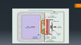
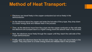
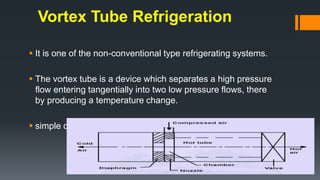
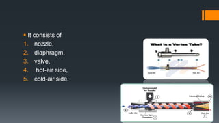
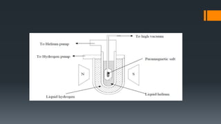
FPE 613 Cold Storage Engineering
Thermo electric refrigeration system
Vortex tube
Cooling by adiabatic demagnetization
Presented by
Princess Monica PS
2019671804
PhD-FPE (1st year)
Course Teacher
Dr.N.Venkatachalapathy
Professor And Head
Food Process Engineering
IIFPT
Thanjavur
Contents :
 Thermo electric refrigeration system
 Vortex tube
 Cooling by adiabatic demagnetization
Introduction
 A thermoelectric refrigerator in the same way is a refrigerator that uses the
Peltier effect to create a heat flux between the junction of two different types of
materials.
 The Peltier effect is a temperature difference created by applying a voltage
between two electrodes connected to a sample of semiconductor material.
This phenomenon can be useful when it is necessary to transfer heat from one
medium to another on a small scale.
 copper connection paths to the power supply.
 the heat will be moved (or 'pumped') in the direction of
charge carrier flow throughout the circuit. actually, it is the
charge carriers that transfer the heat.
 Thermoelectric cooling devices causes the junction to either cool
down(absorbing heat) or warm up (rejecting heat), depending on
the direction of the current.
 The thermo-element materials are doped semiconductors, one n-
type with a majority of negative charge carriers (electrons) and the
other p-type with a majority of positive charge carriers (holes).
 Behind the thermoelectric module an Heat Sink is fitted which
enables the conduction heat transfer from the hot side of module.
 At the cold junction side of the thermoelectric module,
convective heat transfer takes place from air.
 The whole thermoelectric module is fitted in a insulated
chamber
 The whole assembly is connected to DC Power Supply.
WORKING PRINCIPLE
 two ceramic substance that serve as a foundation and electrical
insulation for P-type and N-type Bismuth Telluride
 The ceramics also serve as insulation between the modules
internal electrical elements and a heat sink
 Electrically conductive materials, usually copper pads attached
to the ceramics, maintain the electrical connections inside the
module
 The heat pumping action is actual function of the quantity of
electrons crossing over the p-n junction.
Method of Heat Transport:
 Electrons can travel freely in the copper conductors but not so freely in the
semiconductor.
 As the electrons leave the copper and enter the hot-side of the p-type, they drop down
to a lower energy level and release heat in the process.
 Then, as the electrons move from the p-type into the copper conductor on the cold side,
the electrons are bumped back to a higher energy level and absorb heat in the process.
 Next, the electrons move freely through the copper until they reach the cold side of the
n-type semiconductor.
 Finally, when the electrons leave the hot-side of the n-type, they can move freely in the
copper. They drop down to a lower energy level and release heat in the process.
 Between the heat generating device and the conductor must be an
electrical insulator to prevent an electrical short circuit between the
module and the heat source.
 The electrical insulator must also have a high thermal conductivity so
that the temperature gradient between the source and the conductor
is small.
 Ceramics like alumina are generally used.
Disadvantages
 the limit to their cooling capacity and coefficient of
performance which may be restrictive in the future when heat
transfer demands become much larger.
 A DC power supply is needed for the TE cooler.
ADVANTAGES
 Effective in spot cooling.
 Environmentally friendly.
 Generate no electrical noise.
 Small size and light weight.
 Compact and reliable.
 No moving parts and fluids.
 Durable and maintenance-free.
 Very long operation life.
APPLICATIONS
 Include equipment used by military, medical, industrial,
consumer, scientific/laboratory, and telecommunications
organizations
 Uses range from simple food and beverage coolers for an
afternoon picnic to extremely sophisticated temperature
control systems in missiles and space vehicles.
Vortex Tube Refrigeration
 It is one of the non-conventional type refrigerating systems.
 The vortex tube is a device which separates a high pressure
flow entering tangentially into two low pressure flows, there
by producing a temperature change.
 simple device with no moving parts
 It consists of
1. nozzle,
2. diaphragm,
3. valve,
4. hot-air side,
5. cold-air side.
 Chamber is a portion of nozzle that facilities the tangential entry of high
velocity air-stream into hot side.
 Hot side is cylindrical in cross section and is of different lengths as per
design.
 Valve obstructs the flow of air through hot side and it also controls the
quantity of hot air through vortex tube.
 Diaphragm is a cylindrical piece of small thickness and having a small hole
of specific diameter at the center.
 Air stream traveling through the core of the hot side is emitted through the
diaphragm hole.
 Cold side is a cylindrical portion through which cold air is passed.
Working:
 Compressed air is passed through the nozzle. Here, air expands
and acquires high velocity due to particular shape of the nozzle.
 A vortex flow is created in the chamber and air travels in spiral
like motion along the periphery of the hot side.
 This flow is restricted by the valve.
 partly closing the valve, a reversed axial flow through the core of
the hot side starts.
 By controlling the opening of the valve, the quantity of the cold
air and its temperature can be varied.
Advantages:
 It uses air as refrigerant, so there is no leakage problem.
 Vortex tube is simple in design and it avoids control systems.
 There are no moving parts in vortex tube.
 It is light in weight and requires less space.
 Initial cost is low and its working expenses are also less, where
compressed air is readily available.
 Maintenance is simple and no skilled labors are required.
Disadvantages:
 Its low COP, limited capacity and only small portion of the compressed
air appearing as the cold air limits its wide use in practice.
Applications:
 Vortex tubes are extremely small and as it produce hot as well as
cold air. It may be of use in industries where both are
simultaneously required.
 Temperature as low as –50°C can be obtained without any
difficulty, so it is very much useful in industries for spot cooling of
electronic components.
 It is commonly used for body cooling of the workers in mines.
Cooling by adiabatic demagnetization
 Magnetic refrigeration is based on the magnetocaloric effect,
discovered by E. Warburg in 1881.
 in which a temperature change of a suitable material is caused
by exposing the material to a changing magnetic field.
 Similar to mechanical compression and expansion of gases,
there are some materials that raise their temperatures when
adiabatically magnetised, and drop their temperature when
adiabatically demagnetised.
 Temperature very near the absolute zero may be obtained by
adiabatic demagnetization of certain paramagnetic salts.
Each atom of the paramagnetic salt may be considered to be
a tiny magnet.
 If the salt is not magnetized then all its atoms or the magnets
are randomly oriented.
 If it is exposed to a strong magnetic field, the atoms will align themselves
to the direction of magnetic field.
 the heat will be absorbed by Helium.
 Now if the magnetic field is suddenly removed, the atoms will come back
to the original random orientation.
 If there is no heat transfer from surroundings, the internal energy of the
salt will decrease as it does work. Consequently the salt will be cooled.
 The substance is returned to adiabatic (insulated) condition
so the total entropy remains constant
 the magnetic field is decreased, the thermal energy causes
the magnetic moments to overcome the field, and thus the
sample cools, i.e., an adiabatic temperature change.
 Energy (and entropy) transfers from thermal entropy to
magnetic entropy, measuring the disorder of the magnetic
dipoles.
 Paramagnetic salts like gadolinium sulphate are used.
 This gives lower temperatures for a brief instant of time.
Advantages
 No compressor and refrigerant gas
 Low running cost
 Less environment impact
Disadvantages
 Initial investment is high
 Protection of electronic components from magnetic fields
Applications
 Cryogenic engine
 Magnetic domestic refrigerator , magnetic air conditioning in
building and houses
 Refrigeration in medicine
 Bevarage coolers
 Ice cream cabinets
References
 Diana Enescu.2018.Thermoelectric Refrigeration Principles
 Prashant Gour .2012. Experimental Encountering of Major Problems
Associated with Thermoelectric Refrigeration
 Rajendra. P. Patil .2017. Thermoelectric Refrigeration Using Peltier Effect
 Tejshree Bornare Vortex tube refrigeration system Based on Compressed air.
 Chapter 15 Adiabatic Demagnetization
 Lesson 8 Methods of producing Low Temperatures 1 Version 1 ME, IIT
Kharagpur
Thank you

Fpe 613 cold storage engineering.pptx

  • 1.
    FPE 613 ColdStorage Engineering Thermo electric refrigeration system Vortex tube Cooling by adiabatic demagnetization Presented by Princess Monica PS 2019671804 PhD-FPE (1st year) Course Teacher Dr.N.Venkatachalapathy Professor And Head Food Process Engineering IIFPT Thanjavur
  • 2.
    Contents :  Thermoelectric refrigeration system  Vortex tube  Cooling by adiabatic demagnetization
  • 3.
    Introduction  A thermoelectricrefrigerator in the same way is a refrigerator that uses the Peltier effect to create a heat flux between the junction of two different types of materials.  The Peltier effect is a temperature difference created by applying a voltage between two electrodes connected to a sample of semiconductor material. This phenomenon can be useful when it is necessary to transfer heat from one medium to another on a small scale.
  • 5.
     copper connectionpaths to the power supply.  the heat will be moved (or 'pumped') in the direction of charge carrier flow throughout the circuit. actually, it is the charge carriers that transfer the heat.
  • 6.
     Thermoelectric coolingdevices causes the junction to either cool down(absorbing heat) or warm up (rejecting heat), depending on the direction of the current.  The thermo-element materials are doped semiconductors, one n- type with a majority of negative charge carriers (electrons) and the other p-type with a majority of positive charge carriers (holes).  Behind the thermoelectric module an Heat Sink is fitted which enables the conduction heat transfer from the hot side of module.
  • 7.
     At thecold junction side of the thermoelectric module, convective heat transfer takes place from air.  The whole thermoelectric module is fitted in a insulated chamber  The whole assembly is connected to DC Power Supply.
  • 8.
    WORKING PRINCIPLE  twoceramic substance that serve as a foundation and electrical insulation for P-type and N-type Bismuth Telluride  The ceramics also serve as insulation between the modules internal electrical elements and a heat sink  Electrically conductive materials, usually copper pads attached to the ceramics, maintain the electrical connections inside the module  The heat pumping action is actual function of the quantity of electrons crossing over the p-n junction.
  • 9.
    Method of HeatTransport:  Electrons can travel freely in the copper conductors but not so freely in the semiconductor.  As the electrons leave the copper and enter the hot-side of the p-type, they drop down to a lower energy level and release heat in the process.  Then, as the electrons move from the p-type into the copper conductor on the cold side, the electrons are bumped back to a higher energy level and absorb heat in the process.  Next, the electrons move freely through the copper until they reach the cold side of the n-type semiconductor.  Finally, when the electrons leave the hot-side of the n-type, they can move freely in the copper. They drop down to a lower energy level and release heat in the process.
  • 10.
     Between theheat generating device and the conductor must be an electrical insulator to prevent an electrical short circuit between the module and the heat source.  The electrical insulator must also have a high thermal conductivity so that the temperature gradient between the source and the conductor is small.  Ceramics like alumina are generally used.
  • 11.
    Disadvantages  the limitto their cooling capacity and coefficient of performance which may be restrictive in the future when heat transfer demands become much larger.  A DC power supply is needed for the TE cooler.
  • 12.
    ADVANTAGES  Effective inspot cooling.  Environmentally friendly.  Generate no electrical noise.  Small size and light weight.  Compact and reliable.  No moving parts and fluids.  Durable and maintenance-free.  Very long operation life.
  • 13.
    APPLICATIONS  Include equipmentused by military, medical, industrial, consumer, scientific/laboratory, and telecommunications organizations  Uses range from simple food and beverage coolers for an afternoon picnic to extremely sophisticated temperature control systems in missiles and space vehicles.
  • 14.
  • 15.
    Vortex Tube Refrigeration It is one of the non-conventional type refrigerating systems.  The vortex tube is a device which separates a high pressure flow entering tangentially into two low pressure flows, there by producing a temperature change.  simple device with no moving parts
  • 16.
     It consistsof 1. nozzle, 2. diaphragm, 3. valve, 4. hot-air side, 5. cold-air side.
  • 17.
     Chamber isa portion of nozzle that facilities the tangential entry of high velocity air-stream into hot side.  Hot side is cylindrical in cross section and is of different lengths as per design.  Valve obstructs the flow of air through hot side and it also controls the quantity of hot air through vortex tube.  Diaphragm is a cylindrical piece of small thickness and having a small hole of specific diameter at the center.  Air stream traveling through the core of the hot side is emitted through the diaphragm hole.  Cold side is a cylindrical portion through which cold air is passed.
  • 18.
    Working:  Compressed airis passed through the nozzle. Here, air expands and acquires high velocity due to particular shape of the nozzle.  A vortex flow is created in the chamber and air travels in spiral like motion along the periphery of the hot side.  This flow is restricted by the valve.  partly closing the valve, a reversed axial flow through the core of the hot side starts.  By controlling the opening of the valve, the quantity of the cold air and its temperature can be varied.
  • 20.
    Advantages:  It usesair as refrigerant, so there is no leakage problem.  Vortex tube is simple in design and it avoids control systems.  There are no moving parts in vortex tube.  It is light in weight and requires less space.  Initial cost is low and its working expenses are also less, where compressed air is readily available.  Maintenance is simple and no skilled labors are required. Disadvantages:  Its low COP, limited capacity and only small portion of the compressed air appearing as the cold air limits its wide use in practice.
  • 21.
    Applications:  Vortex tubesare extremely small and as it produce hot as well as cold air. It may be of use in industries where both are simultaneously required.  Temperature as low as –50°C can be obtained without any difficulty, so it is very much useful in industries for spot cooling of electronic components.  It is commonly used for body cooling of the workers in mines.
  • 22.
    Cooling by adiabaticdemagnetization
  • 23.
     Magnetic refrigerationis based on the magnetocaloric effect, discovered by E. Warburg in 1881.  in which a temperature change of a suitable material is caused by exposing the material to a changing magnetic field.  Similar to mechanical compression and expansion of gases, there are some materials that raise their temperatures when adiabatically magnetised, and drop their temperature when adiabatically demagnetised.
  • 24.
     Temperature verynear the absolute zero may be obtained by adiabatic demagnetization of certain paramagnetic salts. Each atom of the paramagnetic salt may be considered to be a tiny magnet.  If the salt is not magnetized then all its atoms or the magnets are randomly oriented.
  • 26.
     If itis exposed to a strong magnetic field, the atoms will align themselves to the direction of magnetic field.  the heat will be absorbed by Helium.  Now if the magnetic field is suddenly removed, the atoms will come back to the original random orientation.  If there is no heat transfer from surroundings, the internal energy of the salt will decrease as it does work. Consequently the salt will be cooled.
  • 27.
     The substanceis returned to adiabatic (insulated) condition so the total entropy remains constant  the magnetic field is decreased, the thermal energy causes the magnetic moments to overcome the field, and thus the sample cools, i.e., an adiabatic temperature change.  Energy (and entropy) transfers from thermal entropy to magnetic entropy, measuring the disorder of the magnetic dipoles.
  • 28.
     Paramagnetic saltslike gadolinium sulphate are used.  This gives lower temperatures for a brief instant of time.
  • 29.
    Advantages  No compressorand refrigerant gas  Low running cost  Less environment impact Disadvantages  Initial investment is high  Protection of electronic components from magnetic fields
  • 30.
    Applications  Cryogenic engine Magnetic domestic refrigerator , magnetic air conditioning in building and houses  Refrigeration in medicine  Bevarage coolers  Ice cream cabinets
  • 31.
    References  Diana Enescu.2018.ThermoelectricRefrigeration Principles  Prashant Gour .2012. Experimental Encountering of Major Problems Associated with Thermoelectric Refrigeration  Rajendra. P. Patil .2017. Thermoelectric Refrigeration Using Peltier Effect  Tejshree Bornare Vortex tube refrigeration system Based on Compressed air.  Chapter 15 Adiabatic Demagnetization  Lesson 8 Methods of producing Low Temperatures 1 Version 1 ME, IIT Kharagpur
  • 32.