EE-371 : ControlSystems
Lecture#02
Introduction to Control Systems
Chapter #01/02
Text Book: Control Systems Engineering by Norman S.
Nise 5th
Edition
Instructor: Dr. Neelma Naz
Class: BEE 14 A/B
School of Electrical Engineering and
Computer Science
Department of Electrical Engineering
1
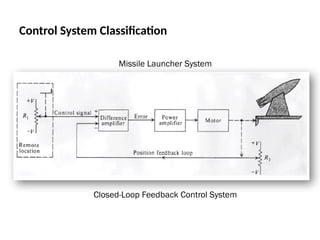
2.
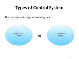
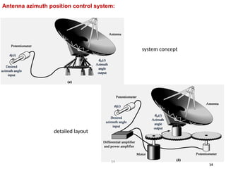
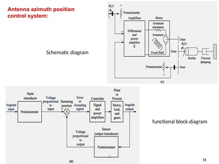
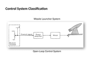
Types of ControlSystem
There are two main types of control system…
Open Loop
System
Closed Loop
System
&
2
3.
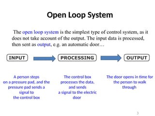
A person steps
ona pressure pad, and the
pressure pad sends a
signal to
the control box
The control box
processes the data,
and sends
a signal to the electric
door
The door opens in time for
the person to walk
through
Open Loop System
The open loop system is the simplest type of control system, as it
does not take account of the output. The input data is processed,
then sent as output, e.g. an automatic door…
3
4.
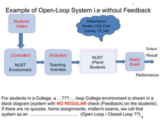
NUST
(Plant)
Students
(Actuator)
Teaching
Activities
(Controller)
NUST
Environment
Disturbance
Parties, Chit Chat
Games,TV, Net
Output
Result
For students in a College, a …???…..loop College environment is shown in a
block diagram (system with NO REGULAR check (Feedback) on the students).
If there are no quizzes, home assignments, midterm exams, we call that
system as an …………………………… (Open Loop / Closed Loop ??)
Yearly
Exam
Performance
Students
Intake
Example of Open-Loop System i.e without Feedback
4
4
5.
Feedback
• Feedback isa key tool that can be used to
modify the behavior of a system.
• This behavior altering effect of feedback is a
key mechanism that control engineers exploit
deliberately to achieve the objective of acting
on a system to ensure that the desired
performance specifications are achieved.
5
6.
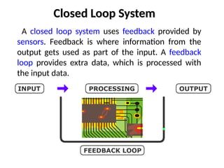
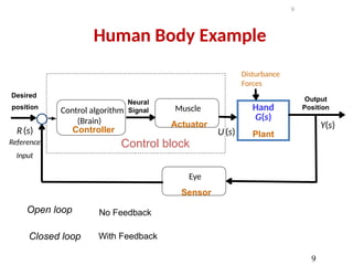
Closed Loop System
Aclosed loop system uses feedback provided by
sensors. Feedback is where information from the
output gets used as part of the input. A feedback
loop provides extra data, which is processed with
the input data.
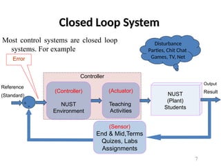
7.
Most control systemsare closed loop
systems. For example
Closed Loop System
Controller
NUST
(Plant)
Students
(Actuator)
Teaching
Activities
(Controller)
NUST
Environment
Reference
(Standard)
(Sensor)
End & Mid,Terms
Quizes, Labs
Assignments
Output
Result
+ -
Error
Disturbance
Parties, Chit Chat
Games, TV, Net
7
8.
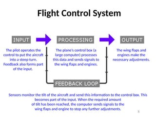
Flight Control System
Thepilot operates the
control to put the aircraft
into a steep turn.
Feedback also forms part
of the input.
The plane’s control box (a
large computer) processes
this data and sends signals to
the wing flaps and engines.
The wing flaps and
engines make the
necessary adjustments.
Sensors monitor the tilt of the aircraft and send this information to the control box. This
becomes part of the input. When the required amount
of tilt has been reached, the computer sends signals to the
wing flaps and engine to stop any further adjustments.
8
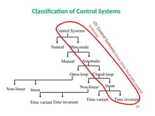
Classification of ControlSystems
Control Systems
Natural Man-made
Manual Automatic
Open-loop Closed-loop
Non-linear linear
Time variant Time invariant
Non-linear linear
Time variant Time invariant
L
T
I
C
o
n
t
r
o
l
S
y
s
t
e
m
s
(
L
i
n
e
a
r
ti
m
e
i
n
v
a
r
i
a
n
t
c
o
n
t
r
o
l
s
y
s
t
e
m
s
)
11
12.
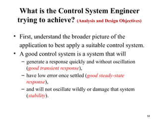
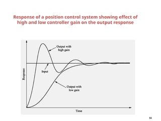
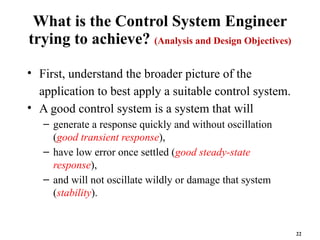
What is theControl System Engineer
trying to achieve? (Analysis and Design Objectives)
• First, understand the broader picture of the
application to best apply a suitable control system.
• A good control system is a system that will
– generate a response quickly and without oscillation
(good transient response),
– have low error once settled (good steady-state
response),
– and will not oscillate wildly or damage that system
(stability).
12
13.
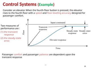
Consider an elevator.When the fourth-floor button is pressed, the elevator
rises to the fourth floor with a speed and floor-leveling accuracy designed for
passenger comfort.
13
Control Systems (Example)
Two measures of
performance are :
(1) the transient
response
(2) the steady-state
error.
Passenger comfort and passenger patience are dependent upon the
transient response
13
Electro-
Mechanical
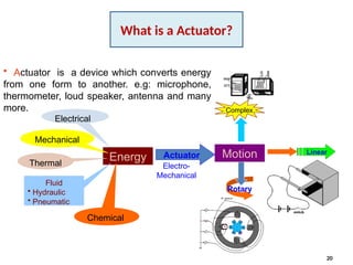
• Actuator isa device which converts energy
from one form to another. e.g: microphone,
thermometer, loud speaker, antenna and many
more.
Energy
Electrical
Thermal
Fluid
• Hydraulic
• Pneumatic
Mechanical
Chemical
Actuator Motion
Rotary
Linear
Complex
20
What is a Actuator?
21.
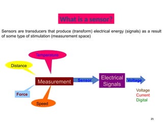
What is asensor?
Measurement
Temperature
Force
Distance
Speed
Sensor
Electrical
Signals
Voltage
Sensors are transducers that produce (transform) electrical energy (signals) as a result
of some type of stimulation (measurement space)
Voltage
Current
Digital
21
22.
What is theControl System Engineer
trying to achieve? (Analysis and Design Objectives)
• First, understand the broader picture of the
application to best apply a suitable control system.
• A good control system is a system that will
– generate a response quickly and without oscillation
(good transient response),
– have low error once settled (good steady-state
response),
– and will not oscillate wildly or damage that system
(stability).
22
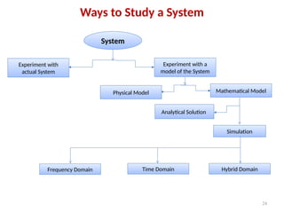
Ways to Studya System
24
System
Experiment with a
model of the System
Experiment with
actual System
Physical Model Mathematical Model
Analytical Solution
Simulation
Frequency Domain Time Domain Hybrid Domain
25.
Model
•
A model isa simplified representation or
abstraction of reality.
•
Reality is generally too complex to model
exactly.
25
26.
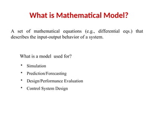
What is MathematicalModel?
A set of mathematical equations (e.g., differential eqs.) that
describes the input-output behavior of a system.
What is a model used for?
• Simulation
• Prediction/Forecasting
• Design/Performance Evaluation
• Control System Design
27.
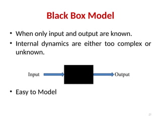
Black Box Model
•When only input and output are known.
• Internal dynamics are either too complex or
unknown.
• Easy to Model
27
Input Output
28.
Grey Box Model
•When input and output and some information
about the internal dynamics of the system is
known.
• Easier than white box Modelling.
28
u(t) y(t)
y[u(t), t]
29.
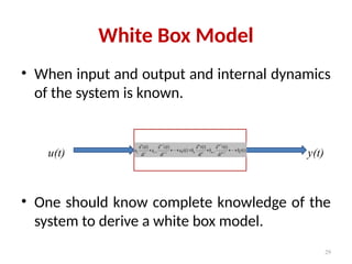
White Box Model
•When input and output and internal dynamics
of the system is known.
• One should know complete knowledge of the
system to derive a white box model.
29
White Box
u(t) y(t)
)
(
)
(
)
(
)
(
)
(
)
(
0
1
1
1
0
1
1
1 t
r
b
dt
t
r
d
b
dt
t
r
d
b
t
c
a
dt
t
c
d
a
dt
t
c
d
a m
m
m
m
m
m
n
n
n
n
n
n
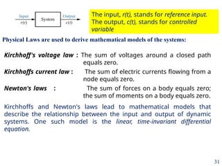
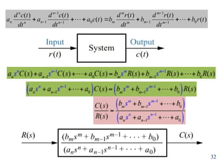
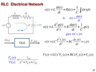
Kirchhoff's voltage law: The sum of voltages around a closed path
equals zero.
Kirchhoffs current law : The sum of electric currents flowing from a
node equals zero.
Newton's laws : The sum of forces on a body equals zero;
the sum of moments on a body equals zero.
Kirchhoffs and Newton's laws lead to mathematical models that
describe the relationship between the input and output of dynamic
systems. One such model is the linear, time-invariant differential
equation.
Physical Laws are used to derive mathematical models of the systems:
The input, r(t), stands for reference input.
The output, c(t), stands for controlled
variable
31
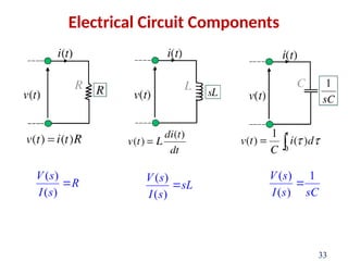
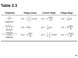
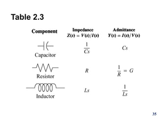
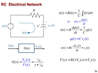
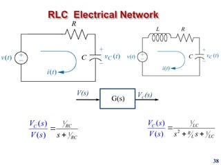
V(s) VC(s)
G(s)
36
0
1
( )( ) ( )
t
v t Ri t i d
C
( ) 1
( ) ( )
dq t
v t R q t
dt C
( ) ( )
c
q t C v t
( )
( )
dq t
As i t
dt
( )
( ) ( )
c
c
dv t
v t RC v t
dt
( ) ( ) ( )
C C
V s RCsV s V s
1
1
( )
( )
( ) RC
R
C
C
V s
V
G s
s
s
#5 Feedback is a very heart of control. Three examples are given for feedback systems in the book. Students are encouraged to read Section 1.2.
#7 For students in a College, a …???…… loop College environment is shown in a block diagram (system with regular check on the students). If there are no quizzes, home assignments, midterm exams, we call that system as
an …………………………….(Open/Closed loop)

![Grey Box Model
• When input and output and some information
about the internal dynamics of the system is
known.
• Easier than white box Modelling.
28
u(t) y(t)
y[u(t), t]](https://image.slidesharecdn.com/ee-371lecture02introduction-250523044744-17e7245e/85/EE-371-Lecture-02-introductionsssssssss-pptx-28-320.jpg)