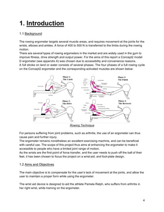
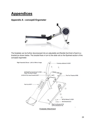
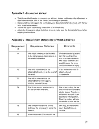
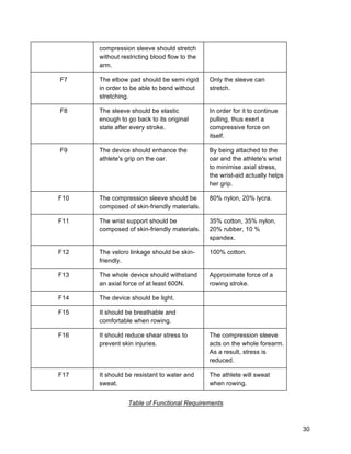
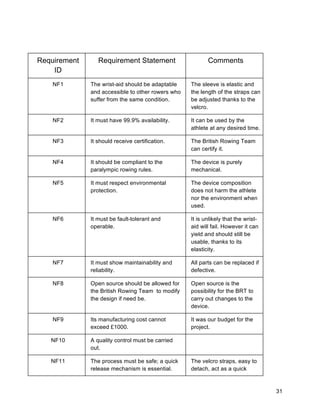
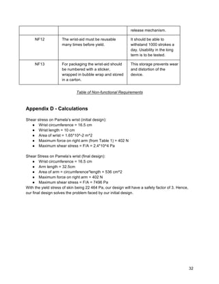
Rowing Ergometer Enhancements
For Limited Joint Range Of Motion
Nicolas Ayoub, Cyril Deroy, Rohit Devesar, Gan Chong Yee, Giuseppe Pietro Gava, Emanuel Olagbaju,
Ayomide Olatunji, Aliyah Rajabalee, Eduardo Rebelo, Pui Sham, Agave Stavropoulou-Tatla, Bo Yang
Department of Bioengineering, Faculty of Engineering
IMPERIAL COLLEGE LONDON
June 22, 2014
Supervised by Dr. Warren Macdonald
This report is a proposal of two enhancements for athletes who suffer from arthritis in the wrist
and bone spurs in the ankle area, in order to facilitate and allow for a more efficient training. The
proposal features a wrist aid design that allows a greater pulling force on the handlebar, and a
footplate that allows an increase in the stroke length by means of a rotating plate.
A wide range of primary and secondary research was conducted in order to support this project,
through a variety of academic resources and experimentation. Relevant data was recorded and
used for the design process. For the wrist aid, it was found that a force of 402 Newton was
exerted on the athlete’s wrist. The aim is to create a device that will withstand part (up to all) of
this force and re-distribute it evenly on the forearm. For the footplate, the aim is to design a
bendable footplate that allows a controllable rotation of no more than 42 degrees.
Risk assessments were carried out to determine the probability and severity of injury whilst
using the devices as well as the likelihood that they fail, and preliminary evaluations showed
that the devices would work for non-cyclic loading. However, to reach the conclusion that this
project has been completely successful, more testing should be done to determine the
performance under intense training conditions.
2
Table Of Contents
1 - Introduction ………………………………………………………………………………………………....................... 4
1.1 Background ……………………………………………………………………………………………………… 4
1.2 Aims and Objectives ……………………………………………………………………………..………………4
2 - Design ………………………………………………………………………………………………………………………. 6
2.1 Requirements ……………………………………………………………...…………………………………….. 6
2.1.1 Footplate Requirements …………………………………………………….……………….…….6
2.1.2 Wrist Aid Requirements ………………………………………………………………………..…..6
2.2 Initial Ideas …………………….………………………………………………………………………………..….6
2.3 Calculations …………………..……………...………………...…………………………………..……………...8
2.4 Final Design ………………………...………………...…………………...……………………………………..11
2.4.1 Wrist Aid Design …...………………………………………………………………………………11
2.4.2 Footplate Design …...……………………………………………………………………………...12
3 - Production …………………...………………………………...…………………………………………………………..15
3.1 Manufacturing Route …………………...…………………………………..…………………………………...15
3.1.1 Wrist Aid Manufacture .……………………………………… …………………………………...15
3.1.2 Footplate Manufacture ……………………………………………………..……………………...16
3.2 Cost …………………...….……………………………...……...………...……………………………………...16
4 - Evaluation …………………...………………………………...…………………………………………………………..20
4.1 Overview Of The Evaluation……………….……………...…………….…………………….........................20
4.1.1 Improve stroke length …………...……………...……………...……………...……………...… 20
4.1.2 Design is adaptable to a large number of users …...………...………...………...………...….20
4.1.3 Ability to resist force exerted on it …...………...………...………...…….……….…..…...…… 21
4.1.4 Allow for simple integration to concept2 model D ergometer…..…...………...………...……..21
4.1.5 Reduction of grip force ………...….………...….………...….………...….………...….………...21
4.2 Risk Analysis …………………...………………………………...….………………………………….………..21
5 - Discussion …………………...………………………………...……….………..………………………………………..24
5.1 Ethical Issues …………………...………………………………….……….…………………..….…………….24
5.1.1 Ethical Summary ……………………………………….…….……..………….…...……………..24
5.1.2 Study Population …………………………………………..………………….…………………...24
5.1.3 Dissemination ………………………………………….…….……….……………………….…...24
5.1.4 Protocol ……………………………………………….…….………...…………………….……...24
5.1.5 Value ………………………………………………….…….……………………………………… 25
5.1.6 Legislation ………………………………………….……..………………………………………..25
5.1.7 Environment / Sustainability ……………………….…..…………………………….……….…..25
5.2 Improvements …………………...…………………………………..……………………………………..…….26
6 - Conclusion …………………...………………………………...…………………………………………………………..26
References ………………….....………………………………...………………….………………………………………….27
3
Appendices …………………….………………………………...……………………………………………………………..28
Appendix A - Concept2 Ergometer…………………………………………………………..………………………28
Appendix B - Instruction Manual …………………………………………………………………………………….29
Appendix C - Requirement Statements…………………………………………………….……………………….29
Appendix D - Calculations…………………………………………………………………………………………….32
4
1. Introduction
1.1 Background
The rowing ergometer targets several muscle areas, and requires movement at the joints for the
wrists, elbows and ankles. A force of 400 to 500 N is transferred to the limbs during the rowing
motion.
There are several types of rowing ergometers in the market and are widely used in the gym to
improve fitness, drive strength and output power. For the aims of this report a Concept2 model
D ergometer (see appendix A) was chosen due to accessibility and convenience reasons.
A full stroke on land or water consists of several phases. The four phases of a full rowing cycle
on the Concept2 ergometer and the corresponding activated muscles are shown below:
Rowing Technique
For persons suffering from joint problems, such as arthritis, the use of an ergometer can thus
cause pain and further injury.
The ergometer remains nonetheless an excellent exercising machine, and can be beneficial
with careful use. The scope of this project thus aims at enhancing the ergometer to make it
accessible to people who have a limited joint range of motion.
As the wrists are the first point of force transfer, and the user needs to push off the ball of their
feet, it has been chosen to focus the project on a wrist-aid, and foot-plate design.
1.2 Aims and Objectives
The main objective is to compensate for the user’s lack of movement at the joints, and allow the
user to maintain a proper form while using the ergometer.
The wrist aid device is designed to aid the athlete Pamela Relph, who suffers from arthritis in
her right wrist, while training on the ergometer.
5
The aims of the wrist aid device are:
● Improve the grip on the handle, thus increasing the strength of the pull provided by the
athlete.
● Provide an attachment from the arm to the handle of the ergometer, while reducing the
load on the wrists and hands.
● Allow wrist movements.
● Ideally, be adaptable for both training and competitive rowing.
The reason for building an adaptation to the footplate is to provide people with limited ankle
flexibility a greater opportunity to achieve a peak level of performance when using a rowing
machine. The footplate of the rowing ergometer is modified to meet the needs of Paralympic
athletes such as James Fox who suffers from bone spurs in his ankles, and to increase their
range of movement.
The design of an adaptive footplate should allow a rower with limited rotation in the ankle to:
● Have an increased stroke length and consequently an increase in the drive and finish
phases by allowing a further reach in the catch position. This will allow the rower to push
off using as much force as possible and minimize the effects of limited dorsiflexion.
● Reduce any loss of power in the drive phase by minimizing the effects of reduced plantar
flexion.
● Increase stamina and endurance to allow a longer and more intense training.
6
2. Design
2.1 Requirements
2.1.1 Foot-Plate Requirements
The main requirement of the proposed footplate is the increase the stroke length of the athlete.
This was achieved by allowing the user to reach further into the catch position with their hips by
decreasing the foot angle to about 30° and therefore increasing the range of movement for
cases of limited ankle flexibility. The proposed footplate is an adaptation of a standard footplate,
fixing the foot in the same way and being able to accommodate various foot sizes . The
footplate must prevent over rotation of the ankle past the standard 42°. Additionally, the
adaptive footplate should resist the loads exerted on it (approximately 470 N in each plate) and
allow the symmetrical movement of both legs.
2.1.2 Wrist-Aid Requirements
A - User Requirements
The athlete needs a device that limits tension to her wrist while rowing. The wrist-aid should be
designed in order to meet her expectations. For the system to be successful, some steps must
be followed.
The wrist aid is most effective when used on a rowing ergometer. The athlete should firstly wear
the sleeve on her right arm, with the elbow pad on the elbow side, and then attach the straps to
the right oar, alongside the right hand grip. This way, the attachment length can be adjusted at
will. The athlete is to execute normal rowing strokes.
The wrist-aid should be easy to put on and should not prevent the athlete from carrying out
normal strokes. Moreover, the device should not cover the athlete’s hands.
B - Functional Requirements
For a detailed functional requirement list, please see appendix C.
The system accomplishes its aim by pulling on the oar in order to minimise the resistive force
applied to the athlete’s wrist.
As soon as the oar is pulled, tension is applied on the athlete’s wrist. The design shows that the
wrist-aid should be composed of two Velcro straps, an elastic compression sleeve, an elbow
pad and a wrist support.
Certain requirements are needed to ensure a good behaviour of the system. The wrist-aid
should compensate the force exerted on the athlete’s wrist and withstand axial force . Its form
and behaviour should change with respect to the athlete’s movement and arm position; the
elastic compression sleeve should stretch when she pulls on the oar and get back to its initial
7
state when she catches. Moreover, it should be breathable (F15), skin-friendly (F10, F11, F12)
and resistant to water and sweat (F17).
C - Non-functional Requirements
For a detailed non-functional requirement list, please see appendix C.
The non-functional requirements are the non-behavioural requirements.
These requirements are focused on the operation of the device such as quality, security and
usability (NF12). As for service requirements, the device should be available for the athlete
(NF2).
The device must meet some quality requirements and must be available for testing (NF10).
It should be designed so that it is as safe as possible for the athlete (NF11).
Since it is a unique prototype, no packaging has been thought of yet. However, a packaging
requirement would be that the device should be numbered (ID) with a sticker, wrapped in bubble
wrap and stored in a carton, to prevent distortion and wear (NF13).
2.2 Initial Ideas
With regards to the wrist aid device, our aim was to transmit the force from wrist to arm, so the
group came up with a design: it consisted of 2 parts, namely the linkage and the wrist support,
the linkage being attached to the extension of the wrist support. One major concern in this
project was that contact with the hand should be avoided as the athlete mentioned that under
cyclic training, contact with the hand often causes blisters. However, in the process of reviewing
this prototype, two major defects were discovered. The first and the most important defect was
high shear pressure on the skin due to insufficient surface area.
It was found that skin injury would occur if the pressure exceeds a certain threshold. The other
disadvantage with this design was the rigid wrist support. During training, the dimensions of the
wrist change, therefore rigid materials are likely to fail. The main focus of the design is to solve
these two problems.
Originally, we planned to base our design for the footplate on a previous project by Hugh
O’Connell who designed a footplate for the same purpose but the whole device would rotate 75°
about another axis instead of the ankle doing the rotation1
. We were thinking of different ways to
rotate the footplate other than using a ball bearing. One idea was to use the backwards motion
of the seat to rotate the footplate, so the footplate only turns the toes as far up and as far
backwards as the seat moves. The problem was that to implement this idea we would need
some pulleys and gears. One of the requirements of the device is to allow simple fixation to a
Concept2 ergometer, this design involving pulleys clearly does not meet that requirement.
1
A Redesigned Rowing Ergometer Footplate for Sufferers of Impaired Ankle Flexibility, Hugh
O’Connell, 2013.
8
Some athletes have resorted to lowering the angle of the footplate which would increase their
stroke length but result in a less powerful stroke. So we decided that we would need a footplate
that could have a reduced angle at the catch and a standard angle during the rest of the rowing
cycle. To achieve this, we split the footplate into two parts so that there is a fixed part for the
rower to drive off whilst still reaching for a more forward catch position. We used 12° because
the athlete this device was designed for usually lowers the foot angle of the plate to about 35°
from 42°, which is about 7°. Any further decrease in angle would not be possible because the
bolts that attach the footplate to the chassis would be in the way.
2.3 Calculations
Step Stroke
Length (mm)
Handle Force
(N)
Suspension ML drift drive ML drift
recovery
R18-min 1 1477 655 6.4 15.8 32.2
R18-min 2 1506 657 5.6 13.3 27.6
R24 1488 667 5.8 22.7 21.7
R28 1467 670 4.8 22 19
MAX 1455 804 4 33.4 33.1
Table 1: Performance of athlete before wrist aid design
The ML drift is the total deviation from the centre line of the ergometer seat in the medial/lateral
direction.
The maximum shear stress produced by our initial design is 24 000 Pa (calculation shown in
Appendix D). As the yield stress for skin tissue is 22 464 Pa, we need to increase the total
surface area of our design to reduce the shear stress.
The user is working against two components of drag, one when holding the handle and the
other transmitted via the chain while he pushes against the footplate. A free body diagram is
shown in the figure below, which includes three external forces. Ff is the force exerted by the
foot on the footplate, Fr the reaction force of the footplate and Fd is the drag force in the chain.
9
Force analysis on the ergometer
Several analyses have been performed to measure the forces that occur during a rowing stroke.
In one of these studies by Baca, Kornfeind and Heller2
, force profiles for four experienced male
rowers were measured. This was done experimentally using load cells in the perpendicular
direction to the footplate and strain gages in the parallel direction. Combining the forces in the
two directions the overall reaction force was obtained. The following graph shows the forces
obtained on each footplate separately and the total force on both footplates for the athletes
working out at the rate of 30 strokes per minute. The x-axis represents the percentage
completeness of the stroke. The average maximum force on each footplate was measured to be
471 ±60 N.
Force Distribution on The Footplate
Another study was performed by Hase et al3
. Again, a force transducer consisting of strain
gauges achieved this and the athletes who took part were 5 elite male rowers. The maximum
force exerted on the handle was about 880N.
This value is consistent with the measurements we took by ourselves from our athlete Pamela
Relph using an instrumented ergometer at Charing Cross hospital. The maximum handle force
we measured at the finish phase was 804N, which makes sense taking into account that she is
a woman.
2
3. Comparison of Foot-Stretcher Force Profiles between On-Water and Ergometer Rowing., Baca. A.,
Kornfeind. P., Heller. M., 2006. XXIV ISBS Symposium 2006, Salzburg – Austria.
3
4. Biomechanics of Rowing Hase, K., Kaya, M., Yamazaki, N., Andrews B.J., Zavatsky, A.B., Halliday,
S.E., 2002, JSME International Journal., Series C, Vol 45, No 4, p1073-1081.
10
Force Distribution on The Handle
The lower and upper limbs are the predominant drivers in generating the whole movement
during the rowing cycle. There are three joints along the leg that are of high interest to be
analysed, the hip, the ankle and the knee and two along the hand, the shoulder and the elbow.
Many different studies have being conducted to measure the joint moments, angular velocities
and contact forces during a rowing cycle. Hase et al4
have calculated joint moments about all
the joints of interest using markers. Then the angular velocity between the segments and the
joint moments were calculated. The contact forces and joint moments for all the joints are
shown below .
Joint Moments
4
4. Biomechanics of Rowing Hase, K., Kaya, M., Yamazaki, N., Andrews B.J., Zavatsky, A.B., Halliday,
S.E., 2002, JSME International Journal., Series C, Vol 45, No 4, p1073-1081.
11
Contact Forces
2.4 Final Design
2.4.1 Wrist Aid Design
To tackle the first problem, we increased the area of contact by extending the wrist support to
cover the entire forearm. It ends right after the elbow, which provides a fixation point for the
whole device. This design produces a maximum shear stress of 7496 Pa (calculation shown in
Appendix D). With the yield stress of skin being 22 464 Pa, our design will have a safety factor
of 3. To address the second issue, we removed the rigid part of the wrist support. Instead,
connection is achieved by directly attaching the linkage to the near end of the extended wrist
support. The whole device is shown in the figure below, followed by a detailed discussion of the
individual parts.
Final Design of the Wrist Aid Device
12
A compression sleeve is used as the extension of the wrist support. It provides relatively uniform
compressive force to the skin is covering, which, in turn, creates friction. The sleeve is
extremely breathable. This feature allows easy cooling and prevents heat accumulation and
performance drop. The Velcro hoop on the upper arm is to tighten the compression sleeve so
that it does not slide down under cyclic training. It is highly stretchable so that blood circulation
to the forearm is not compromised.
The elbow pad is acting as a main force transmitter, being stitched onto the compression
sleeve. In driving phase, as the athlete flexes her arm, the elbow pad will be held in place, so as
to pull the Velcro strap that is linking the elbow pad to the ergometer handle. The wrist support
is stitched to the compression sleeve using elastic thread. It is put underneath the sleeve and
the Velcro strap is anchored onto it.
The Velcro strap consists of two parts. One is worn around the ergometer handle and the other
is attached to the compression sleeve. The handle part of Velcro strap has two loops that can
be adjusted to grab the handle whereas the part on the sleeve is only made up by the
complementary Velcro to the handle part so that the two parts can be tightly attached.
There are two reasons behind the choice Velcro. The first reason is that Velcro is adjustable, in
case of dimensional change or change of relative position between the hand and handle,
adjustment can be easily done to fit to the new situation. The second reason is related to safety.
In case the athlete needs to be quickly disconnected from the handle, the athlete can use her
other hand to pull the tip of the Velcro strap and quickly detach herself from the handle to
prevent any potential injury.
2.4.2 Footplate Design
The footplate consists of 3 main parts: the upper moving plate, the lower fixed plate and the
chassis/bracket which fixes the footplate to the ergometer. We split the footplate itself into two
sections (upper and lower) connected by a Tru-Close hinge which allows for the upper plate to
rotate as the rower approaches the catch position. A thin, flat steel platform extends from the
bracket to prevent the footplate rotating past 12 degrees. The amount of rotation can be
adjusted by placing nylon blocks of different sizes with double sided tape onto this steel
platform. The lower plate remains fixed and is the only part of the footplate to be welded to the
bracket, holding it in place. Finally the plastic ‘flex foot’ with a strap is screwed to the upper steel
plate only so it rotates with it.
13
Left: shows the footplate in it’s regular position when the rower is finishing the drive phase. The
steel bar extending from the bracket is the restriction mechanism where the nylon blocks of
different sizes can be attached by double sided tape.
Right: The upper plate at it’s maximum rotation once it’s been stopped by the steel platform.
Here the rower is in the catch position.
The lowered angle of the upper footplate about the hinge is, essentially, the performance
enhancing factor. This feature provides James (or any other rower) with an extra 12 degrees of
rotation clockwise- thus allowing him to get further forward in the catch position than he
previously could. The implications are that his stroke length will increase as he drives from a
position further forward (closer to the front of the ergometer). An increase in stroke length is
directly related to an improvement in performance.
Both plates were joined by a Tru-Close hinge which is a branded hinge
with a built in torsion spring usually used for heavy duty self closing gates.
The hinge was screwed onto each plate, holding them together. Using a
torsion spring meant that there was some resistance in the moving plate
for the rower to push against on the upper plate when driving. It also lifts
the upper plate back to it’s original position which means the rower is not
using energy lifting the plate back up with the footstrap when driving. We
decided to use the branded Tru-Close hinge instead of any other torsion
spring/hinge combination because of one key factor - the tension in the
spring is adjustable. The hinge can be tightened with a screwdriver to
increase the tension which is important so that the rower can adjust how
much resistance they need when driving. This is a patented feature of the
Tru Close hinge. The returning force provided by the hinge is sufficiently
large enough to lift the upper plate to it’s original position. It is also made
out of high density plastic decreasing the amount of maintenance needed
(no metal rust).
14
Due to our design requiring only the lower plate to be fixed in place, we had to adapt the
supporting bracket to allow for the upper plate to move freely without being in contact with the
bracket. This was implemented by welding the lower plate at a very slight angle to the bracket
and by making it slightly wider than the upper plate. The side of the lower plate was welded onto
the bracket and it was also welded onto a diagonal support beneath it.
Fixing the lower plate to the bracket was significant because we found that heel contact is an
important part of the drive phase, as all the force from the calf muscles are exerted through the
ankles. The plates were split at a distance just past the ankle to ensure all the force exerted
went through the bottom plate. The entire bracket was adapted so that it could be screwed onto
the ergometer at the same points as the normal supporting bracket and be aligned such that the
footplate would be at the same height and position as a regular one.
Footplate designed using Geomagic Design
Extending from the bracket was our restriction mechanism to stop the upper plate rotating too
far and to provide something solid for the rower to drive off. We also developed a few nylon
blocks of different thickness that can be attached to this steel restriction mechanism by using
double sided tape. This gives the rower more options in how far they would like the upper plate
to rotate, depending on how impaired the users dorsiflexion is. We added this feature so that the
footplate could be adaptable and other athletes could benefit from training with it.
15
3. Production
3.1 Manufacturing Route
3.1.1 Wrist Aid Manufacture
After choosing a selection of different materials and components, we bought them off the
Internet and local shops. Our plan was to assemble these parts while testing them ourselves.
This was to enhance our design and assembling efficiency, as we could discard parts that did
not match our desires.
We started creating a prototype and testing it on those of us with similar arm dimensions to
Pamela. Having multiple copies of the same part we could experiment with various
combinations and possible ways to put our project together.
It took us one week to come up with a prototype, which we then handed to a professional to get
it stitched up and replicate our design overall enhancing the quality and precision of the cuts
and stitching.
The steps in building the sleeve of our wrist aid are:
● Marking where the compressive sleeve stretches, when the arm is contracted, and thus
enabling us to find the points where to stitch the elbow support.
● Cut out the elbow rigid support from the elbow pad sleeve and stitch it to the
compressive sleeve using elastic thread.
● The wrist support is stitched to the inside of the far end of the sleeve (the one that fits
around the wrist) using an elastic thread.
● A Velcro strap is attached to the outer side of the upper end of the sleeve (the one that
fits around the bicep and triceps), to secure the sleeve in place.
● The linkage is then attached to the sleeve thanks to a Velcro strap stitched to the ventral
side of the sleeve that fits around the forearm.
The steps to build the linkage of our wrist aid are:
● Cut a long Velcro strap into well sized and designed pieces.
● Stitch the pieces together to create a linkage that is connected both to the sleeve and
the handlebar via Velcro strap, thus is adjustable in two ways.
The overall quality was overall satisfactory and allowed us to test and present the effectiveness
of our design.
Having the design industrially produced would not only decrease the cost of the device
significantly, but also increase the overall quality and function even more. For example, the
elbow pad could be included, during manufacturing, in the design of the compressive sleeve,
without any need for stitching, thus increasing the efficiency and the homogeneity of the pull
provided by the elbow pad and also the structural integrity of the whole device.
16
3.1.2 Footplate Manufacture
After designing a footplate appropriate to our athletes needs, we decided upon the materials
that would suit the requirements necessary for our footplate, while still being cost efficient.
Making a compromise between the two we decided to use 304-grade steel to create the
footplate support bracket and a hinge pin & torsion spring. The steel was ordered from Smith’s
Metals (14) and the spring from Fence Max (15). We ordered a 0.5m x 0.5m sheet of 304-grade
steel of 3mm thickness to construct our footplate from.
Steps:
● Marking out the appropriate areas on our sheet of steel
● Using a foot shear, cut the three separate pieces of the footplate, and the supports to go
underneath
● Drill holes for the screws and bolts required to hold the bracket in place
● Attach the steel together to form the bracket by welding them together
● Screw the hinge pin into place
We decided that it would be best to drill the holes, before connecting the pieces together, as it
would be an awkward shape to drill with after fully assembling the bracket. The drilling was done
using a pillar drill. As the locations of the holes would be the same as the built in footplate, there
is no need to get additional bolts and screws as the existing ones can be used. To attach the
footplate to an ergometer, the built in footplate must first be removed.
3.2 Cost
The manufacturing costs of the materials used need to be analysed in order to estimate the
availability in the market and to give an idea of the selling price.
Below is a table of the materials needed for the initial designs and their corresponding market
prices (W is wrist aid device, F is footplate):
17
Footplate (F)/
Wrist aid (W)
Material Quantity of
material
required
Amount
(GBP)
W Compression sleeve 1 19
W Net thread 4 30
W Wrist support 1 2
W Linkage 2 0.2
F Metal sheet (stainless steel-Grade 440F) 1 70
F Torsion spring (Steel) 2 28
F Screw (Steel) 8 6
F Shoe plates and straps (plastic) 2 30
Total amount for the wrist aid - 51.2
Total amount for the footplate - 134
Total amount - 185.2
Table 2: Expected material list, for the initial design, with cost
The total price of the materials needed for two devices is expected to be £275.75.
However, there are other costs that need to be considered for the whole manufacturing process,
such as postage, packaging and fabrication. Therefore, the total cost should be higher. Due to
changes in the final design, some additional materials were included into the shopping list and
after re-evaluation the total cost is expected to be £368.2.
18
Footplate
(F)/ Wrist
aid (W)
Material/ process Quantity
of
material
required
Material
cost(VAT
included)
(GBP)
Postage
and
packing
cost
(GBP)
Manufacturin
g cost (GBP)
Total
cost
(GBP)
W Buckles(30mm and 40mm) 2 bags 6.72 4.36 0 11.08
W Compressive sleeve(size S, M and
L)
3 19 0 0 47
W Wrist support 1 6.75 0 0 6.75
W Velcro strap(25mm x 68mm) 1 5.48 0 0 5.48
W Cotton Strap(1000mm x 28mm) 1 6 6.5 0 12.5
W Rubber sheet(30mm x 1.5mm x 5m) 1 21.23 10.5 0 31.73
W Elbow pad 2 19.99 0 0 39.98
W Component combination - - - 40 40
F Tru close hinge 1 33.84 47.81 0 81.65
F Steel plate 1 87.20 - 0 87.20
F Screw 4 17p - - 68p
F Double side sticky tape 1 4.15 - - 4.15
Total amount for the wrist aid - - - - 194.52
Total amount for the footplate - - - - 173.68
Total amount - 275.75 - - 368.20
Table 3: Final material list with detailed cost
Making use of the wasted materials (since only a small amount of the materials ordered is used
to produce one prototype of the design) can reduce the cost.
Due to the variation in the dimensions required for different individuals, there is a possibility that
leads to higher production cost. However, there should be less variation in the overall cost of the
footplate.
The production cost of both devices could be further reduced if produced in bulk. Nowadays, in
the UK, there are 10 million people suffering from arthritis, most of who are over 50 years old.
Also, according to the British Rowing Council, there are 32,000 registered members ranging
from age 11 to 80. As adaptive rowers are made aware of our devices through advertisement
19
and promotion, there would be a larger potential market for rowing adaptive devices. With the
increased demand, the manufacturing cost could be sufficiently decreased. The exact cost of
the two designs still needs to have more statistically data to prove if they are sold in real market.
20
4. Evaluation
4.1 Overview of the evaluation
This section will detail how the final design fulfilled all of the functional and non-functional
requirements.
4.1.1 Improve stroke length
To increase their stroke length during a rowing cycle, many athletes have often resorted to try
and get their shoulders, hips or both further into the catch position. Quite often rowers over-
reach with their shoulders, which increases the likeliness of injury and also results in a less
powerful stroke. Reaching further into the catch with the hips is a better approach because it
does not change the stroke sequence i.e. it allows the hips to move first, initiating the movement
and then the back begins to move in conjunction with the hips and knees, and finally the
shoulders. Other approaches include lowering the feet or reducing the foot angle, which
lengthens the stroke but also results in a less powerful stroke. Our design aims to improve the
stroke length by lowering the foot angle, allowing the hips to move further into the catch
position. The fixed bottom plate, which is at the same angle as a standard ergometer, allows the
athlete to push off the footplate during the drive phase the same way as they would with the
standard foot angle, thus resulting in little or no power loss.
The wrist aid device, transferring the stress from the handicapped wrist to the elbow, increases
the net pull that the athlete can achieve, thus allowing a more powerful stroke.
4.1.2 Design is adaptable to a large number of users
The foot angle is fully adjustable by using the plastic stopping blocks, the adjustable hinge or
both. It can be used as a standard footplate. Increasing the tension in the hinge increases the
force with which you have to push down on the top part to depress it. It also increases the
amount of force with which your foot is forced back into the 42° position, this can of course be
adjusted to whatever the user feels comfortable with. The user could adjust both footplates to
provide a symmetrical movement of both legs (compensate for whichever leg is not dominant).
The plastic ‘flex foot’ attaches the same way as to a standard ergometer, providing the same
degree of variability to athlete's shoe sizes.
The wrist aid device is designed to fit different ergometer and different arm sizes too, thanks to
the Velcro loops and straps, which are highly adjustable. The size of the sleeve can be chosen
to fit the size of any athlete’s arm.
21
4.1.3 Ability to resist forces exerted on it
For the footplate design, we used a steel sheet to make the plate whilst the ergometer is made
from aluminium plates. Our footplate can withstand more force than a standard footplate but this
is unnecessary, as aluminium has been proven to withstand the maximum force exerted when
rowing and it has the added benefit of being lighter. This should be a consideration in any
further work on this project.
4.1.4 Allow for simple integration to concept2 model D ergometer
The footplate has exactly the same clearance holes as the standard footplate so the same
screws and bolts can be used to attach it to the concept2 model D ergometer.
The wrist aid has Velcro loops and straps with adjustable length. This feature makes it easy to
fit the device to ergometers with different handle size and to fit athletes with different limb
dimensions.
4.1.5 Reduction of Grip Force
For the wrist aid, the flexion of the arm, which introduces a length increase from the elbow to
hand, further stretches the Velcro strap and pulls the handle. This helps alleviate the grip force
required to hold the handle during drive phase. This would allow symmetrical posture and
reduce back and shoulder injuries faced by rowers with arthritis in prolonged training.
4.2 Risk Analysis
The risk analysis is essential to all engineering projects as it identifies any potential hazardous
issues that could arise from using the device. The risk is computed by probability and severity,
which can easily be observed in the risk analysis table (where the total risk score is the
multiplication of the probability of occurrence and severity risk scores). The optimum design is
achieved by getting the best control according to the risk analysis.
The probability of occurrence is the likelihood of risk occurrence, ranging from 0 (very unlikely)
to 3 (more likely). The severity quantifies the risk of injury and harm to the user, ranging from 1
(unlikely to cause a health issue) to 5 (fatality or permanent injury).
The risk of usage of the device is hence divided into four categories, low (score 1-3), medium
(score 4-7), high (8-11) and very high (score 12-16). Any risk, which is high or very high, should
be supervised during the process.
Risk analysis table is shown below. The overall use, equipment and environment risks of the
two designs are within acceptable range.
22
Associated risk
caused by the
part of design
Event Control Probability
of
occurrence
Severity Total risk
score
Failure of the
footplate
(1F) Broken ankles,
pulled muscles,
twisted ankles or
sprains
Test the
footplate
before use
1 3 3
Failure of
spring
(2F) Pulled
muscles as the
footplate wouldn’t
return to its starting
position
Test the
footplate
before use
1 3 3
Table 4: Details of risk in footplate design
Associate risk
caused by the
part of design
Event Control Probability
of
occurrence
Severity Total risk
score
Usage of over-
tightened and
rough
compression
sleeve
(1W) tissue
damage (i.e. blisters,
skin burns)
Design
individual size
of sleeve. Soft
compression
sleeve used
(soft skin
contact)
2 3 6
Wrist aid
slipping off
during usage
(2W) hair could be
ripped off
Velcro straps
to maintain
wrist in place
1 3 3
Failure of quick
release
(3W) sprained the
wrist
Check design
regularly
1 3 3
Table 5: Details of risk in wrist design
23
Probability of occurrence
0 1 2 3
Severity
1
2
3 (1), (2),
(4),(5)
(3)
4
5
Table 6: Table of the risk analysis
The risk is low, and the design doesn’t need to be changed.
The risk is medium, and the design is still acceptable.
The risk is high, and the design should be improved.
The risk is very high, and the design is unacceptable.
24
5. Discussion
5.1 Ethical Issues
5.1.1 Ethical Summary
Our design complies with various ethical concerns, in terms of safety, confidentiality,
environmental impact and legislation, as delineated in the sections below. Amongst the main
ethical issue we faced was the struggle between consumers needs, scientific integrity and
safety. Whilst our initial wrist aid design fits our athlete’s demand for a more non-obtrusive and
breathable device, our data has shown that such design will induce more shear stress, which
would cause friction and blisters in prolonged use. After much deliberation within our team about
reconsideration of our design due to the tight deadline, we decided to put our athlete’s safety at
top priority and modify our design to account for this additional stress.
5.1.2 Study Population
The study is conducted on Pamela Relph for the wrist aid device and on James Fox for the
footplate device. Verbal consensus has been reached between the respective athletes and our
team to disclose information on stroke length, handle force, drift drive etc. with and without our
equipment. Visual images and videos taken are circulated only within the design team and is
kept in a password protected thumb drive. These files will be deleted upon the completion of our
project.
5.1.3 Dissemination
The results and performance data measured from the respective athletes will be published in
the “Rowing Ergometer Enhancements for Limited Joint Range of Motion” report and in our
presentation for the perusal of Imperial College London, the participants of the experiment and
the general public.
5.1.4 Protocol
● Footplate
○ To prevent injuries due to failure of footplate, it is tested manually by hand before
being used by the athletes.
○ The spring is tightened to an optimum level and a block is used to ensure
adequate foot extension for each respective athlete to prevent pulled muscles.
Our team tests failure of spring beforehand so that it would return to starting
position every time the footplate is pushed forward.
○ The footplate dimension is modelled after the Concept2 Model D ergometer used
by Charing Cross Hospital where experiment is conducted, avoiding mismatch.
25
○ Manufacturing is done only by members who have undergone training in
mechanics workshop under the supervision of technicians to prevent severe
injuries and cuts, and damage to machines.
○ Members well adept with tools do dismantling and assembling of footplate into
ergometer devices, whilst wearing gloves to prevent cuts and blisters.
● Wrist Aid
○ Each sleeve is tailored made for athletes to prevent over-tightening of wrist aid
device which might cause tissue damage. Soft compression sleeves are also
used to provide soft skin contact.
○ Velcro straps are used to maintain device in place, to prevent it from slipping off
and consequently causing sprains and ripping off hair.
○ The device and its quick release mechanism are tested to prevent dislocation.
○ Members experienced with stitching and glue do manufacturing. Members are
equipped with gloves and thimble to prevent blisters and cuts.
5.1.5 Value
Information obtained from the study hopes to provide a better understanding in the effects of
limited joint range of motion due to bone spurs in ankles and wrist arthritis towards adaptive
rowing, and ways to alleviate them. It is with hope that our study will aid athletes in increasing
their performance and the scientific community and manufacturers who wish to create and
improve designs in adaptive rowing.
5.1.6 Legislation
According to the 2012 FISA Adaptive Rowing Regulations, standards are set within the adaptive
boats, seats, straps and eyewear. For the LTA Mixed Coxed four (LTAMix4+) event participated
by our clients, no restrictions are set within alterations in ergometers and training equipment.
Our designs adhere to the legislation set by FISA, as they are not used on the water and aims
to solely aid athletes in their training environment.
5.1.7 Environment / Sustainability
The research and manufacturing of our design has minimal intrusion on environmental grounds.
Tests are only carried out amongst our clients with zero animal/microorganism testing required.
Manufacturing requires small amounts of metal sheets, screws and Velcro, which causes
minimal pollution.
26
5.2 Improvements
Currently the footplate prototype is only designed for training on the ergometer.
If it could be adapted to the rowing boat (following the FISA regulations), then it would enhance
any athlete’s performance that have limited ankle rotation during on-water training and events.
We could also use lighter materials like Aluminium and enhance the attachment of the footplate
to the support platform (i.e. use a more accurate technique than welding).
6. Conclusion
As seen from the results, the wrist-aid design allows force to be transferred to the elbow joint
through the elbow pad, instead of the wrists. The user is thus able to compensate for the lack of
grip and wrist movement through the elbow, while still maintaining a proper form and rowing.
However, the design requires custom made sleeves for maximum efficiency.
The footplate design allows users to increase their stroke length by lowering the foot angle. This
caters to users with limited range of motion at the ankles and does not affect the force applied
when pushing off the plate during the drive phase. The design is completely customisable to fit
the needs of individual users.
While the footplate device can be easily adapted for rowing, the wrist-aid device can only be
used to improve the grip on oars. Another design should be implemented for folding the oars
when rowing.
27
References
1. www.britishrowing.org
2. http://paralympics.org.uk/paralympicsports/rowing
3. http://www.worldrowing.com/uploads/files/8_2012_Adaptive_Rowing_Regulations_2010
11.pdf
4. http://www3.imperial.ac.uk/researchethicscommittee
5. Engineering Ethics: Responsible Conduct of Research slides by Dr. Warren Macdonald
6. http://www.nhs.uk/Conditions/Arthritis/Pages/Introduction.aspx
7. http://www.arthritisresearchuk.org/arthritis-information/data-and-statistics.aspx
8. http://www.britishrowing.org/about-us/structure
9. http://www.usrowing.org/DomesticRowing/AdaptiveRowing/AboutAdaptive.aspx
10. http://www.bioscience.heacademy.ac.uk/ftp/Resources/ethicsbrief1.pdf
11. http://www.row2k.com/columns/623/Coach-Kaehler--How-are-you-finding-more-length-
in-your-rowing-stroke-/#.U6c8jvldVhe
12. http://en.wikipedia.org/wiki/Requirements_analysis
13. http://www.cs.fsu.edu/~lacher/courses/COP3331/rad.html
14. http://www.smithmetal.com/
15. http://www.fencemax.com/
28
Appendices
Appendix A - concept2 Ergometer
The footplate can be further decomposed into an adjustable and flexible foot that is fixed to a
bracket as shown below. The bracket fixes in turn to the slide rail on the flywheel section of the
concept2 ergometer.
Footplate Attachment
29
Appendix B - Instruction Manual
● Wear the wrist aid device on your arm, as with any sleeve, making sure the elbow pad is
right over the elbow, thus in the correct position to pull optimally.
● Make sure the wrist support fits comfortably and does not interfere too much with the few
wrist movements needed.
● Secure the upper Velcro strap on the arm to fit comfortably.
● Attach the linkage and adjust its Velcro straps to make sure the device is tightened when
gripping the handlebar.
Appendix C - Requirement Statements for Wrist aid Device
Requirement
ID
Requirement Statement Comments
F1 The elbow pad should be attached
to the compressive elastic sleeve at
the level of the elbow.
When the athlete pulls the
oar, the bending of her
arm stretches the sleeve.
The elbow pad helps the
stretching and the force
distribution to avoid injury.
F2 The wrist support should be
attached to the sleeve at the level of
the wrist.
It is a more solid base to
attach external
components.
F3 The velcro straps should be
attached to the wrist support,
pointing towards the oar.
F4 The straps should be attached to
the oar on their other end.
The straps pull on the oar
and transfer tension to the
elastic sleeve. The sleeve
will stretch and pull to get
back to its initial position.
Thus the system will help
the athlete pull on the oar.
F5 The compression sleeve should
distribute the force evenly along the
forearm.
This way, the risk of skin
injury due to friction is
minimal.
F6 When the athlete pulls the oar, the
30
compression sleeve should stretch
without restricting blood flow to the
arm.
F7 The elbow pad should be semi rigid
in order to be able to bend without
stretching.
Only the sleeve can
stretch.
F8 The sleeve should be elastic
enough to go back to its original
state after every stroke.
In order for it to continue
pulling, thus exert a
compressive force on
itself.
F9 The device should enhance the
athlete's grip on the oar.
By being attached to the
oar and the athlete's wrist
to minimise axial stress,
the wrist-aid actually helps
her grip.
F10 The compression sleeve should be
composed of skin-friendly materials.
80% nylon, 20% lycra.
F11 The wrist support should be
composed of skin-friendly materials.
35% cotton, 35% nylon,
20% rubber, 10 %
spandex.
F12 The velcro linkage should be skin-
friendly.
100% cotton.
F13 The whole device should withstand
an axial force of at least 600N.
Approximate force of a
rowing stroke.
F14 The device should be light.
F15 It should be breathable and
comfortable when rowing.
F16 It should reduce shear stress to
prevent skin injuries.
The compression sleeve
acts on the whole forearm.
As a result, stress is
reduced.
F17 It should be resistant to water and
sweat.
The athlete will sweat
when rowing.
Table of Functional Requirements
31
Requirement
ID
Requirement Statement Comments
NF1 The wrist-aid should be adaptable
and accessible to other rowers who
suffer from the same condition.
The sleeve is elastic and
the length of the straps can
be adjusted thanks to the
velcro.
NF2 It must have 99.9% availability. It can be used by the
athlete at any desired time.
NF3 It should receive certification. The British Rowing Team
can certify it.
NF4 It should be compliant to the
paralympic rowing rules.
The device is purely
mechanical.
NF5 It must respect environmental
protection.
The device composition
does not harm the athlete
nor the environment when
used.
NF6 It must be fault-tolerant and
operable.
It is unlikely that the wrist-
aid will fail. However it can
yield and should still be
usable, thanks to its
elasticity.
NF7 It must show maintainability and
reliability.
All parts can be replaced if
defective.
NF8 Open source should be allowed for
the British Rowing Team to modify
the design if need be.
Open source is the
possibility for the BRT to
carry out changes to the
device.
NF9 Its manufacturing cost cannot
exceed £1000.
It was our budget for the
project.
NF10 A quality control must be carried
out.
NF11 The process must be safe; a quick
release mechanism is essential.
The velcro straps, easy to
detach, act as a quick
32
release mechanism.
NF12 The wrist-aid must be reusable
many times before yield.
It should be able to
withstand 1000 strokes a
day. Usability in the long
term is to be tested.
NF13 For packaging the wrist-aid should
be numbered with a sticker,
wrapped in bubble wrap and stored
in a carton.
This storage prevents wear
and distortion of the
device.
Table of Non-functional Requirements
Appendix D - Calculations
Shear stress on Pamela’s wrist (initial design):
● Wrist circumference = 16.5 cm
● Wrist length = 10 cm
● Area of wrist = 1.65*10^-2 m^2
● Maximum force on right arm (from Table 1) = 402 N
● Maximum shear stress = F/A = 2.4*10^4 Pa
Shear Stress on Pamela’s wrist (final design):
● Wrist circumference = 16.5 cm
● Arm length = 32.5cm
● Area of arm = circumference*length = 536 cm^2
● Maximum force on right arm = 402 N
● Maximum shear stress = F/A = 7496 Pa
With the yield stress of skin being 22 464 Pa, our design will have a safety factor of 3. Hence,
our final design solves the problem faced by our initial design.

EDPReportFinalVersion

  • 1.
    Rowing Ergometer Enhancements ForLimited Joint Range Of Motion Nicolas Ayoub, Cyril Deroy, Rohit Devesar, Gan Chong Yee, Giuseppe Pietro Gava, Emanuel Olagbaju, Ayomide Olatunji, Aliyah Rajabalee, Eduardo Rebelo, Pui Sham, Agave Stavropoulou-Tatla, Bo Yang Department of Bioengineering, Faculty of Engineering IMPERIAL COLLEGE LONDON June 22, 2014 Supervised by Dr. Warren Macdonald This report is a proposal of two enhancements for athletes who suffer from arthritis in the wrist and bone spurs in the ankle area, in order to facilitate and allow for a more efficient training. The proposal features a wrist aid design that allows a greater pulling force on the handlebar, and a footplate that allows an increase in the stroke length by means of a rotating plate. A wide range of primary and secondary research was conducted in order to support this project, through a variety of academic resources and experimentation. Relevant data was recorded and used for the design process. For the wrist aid, it was found that a force of 402 Newton was exerted on the athlete’s wrist. The aim is to create a device that will withstand part (up to all) of this force and re-distribute it evenly on the forearm. For the footplate, the aim is to design a bendable footplate that allows a controllable rotation of no more than 42 degrees. Risk assessments were carried out to determine the probability and severity of injury whilst using the devices as well as the likelihood that they fail, and preliminary evaluations showed that the devices would work for non-cyclic loading. However, to reach the conclusion that this project has been completely successful, more testing should be done to determine the performance under intense training conditions.
  • 2.
    2 Table Of Contents 1- Introduction ………………………………………………………………………………………………....................... 4 1.1 Background ……………………………………………………………………………………………………… 4 1.2 Aims and Objectives ……………………………………………………………………………..………………4 2 - Design ………………………………………………………………………………………………………………………. 6 2.1 Requirements ……………………………………………………………...…………………………………….. 6 2.1.1 Footplate Requirements …………………………………………………….……………….…….6 2.1.2 Wrist Aid Requirements ………………………………………………………………………..…..6 2.2 Initial Ideas …………………….………………………………………………………………………………..….6 2.3 Calculations …………………..……………...………………...…………………………………..……………...8 2.4 Final Design ………………………...………………...…………………...……………………………………..11 2.4.1 Wrist Aid Design …...………………………………………………………………………………11 2.4.2 Footplate Design …...……………………………………………………………………………...12 3 - Production …………………...………………………………...…………………………………………………………..15 3.1 Manufacturing Route …………………...…………………………………..…………………………………...15 3.1.1 Wrist Aid Manufacture .……………………………………… …………………………………...15 3.1.2 Footplate Manufacture ……………………………………………………..……………………...16 3.2 Cost …………………...….……………………………...……...………...……………………………………...16 4 - Evaluation …………………...………………………………...…………………………………………………………..20 4.1 Overview Of The Evaluation……………….……………...…………….…………………….........................20 4.1.1 Improve stroke length …………...……………...……………...……………...……………...… 20 4.1.2 Design is adaptable to a large number of users …...………...………...………...………...….20 4.1.3 Ability to resist force exerted on it …...………...………...………...…….……….…..…...…… 21 4.1.4 Allow for simple integration to concept2 model D ergometer…..…...………...………...……..21 4.1.5 Reduction of grip force ………...….………...….………...….………...….………...….………...21 4.2 Risk Analysis …………………...………………………………...….………………………………….………..21 5 - Discussion …………………...………………………………...……….………..………………………………………..24 5.1 Ethical Issues …………………...………………………………….……….…………………..….…………….24 5.1.1 Ethical Summary ……………………………………….…….……..………….…...……………..24 5.1.2 Study Population …………………………………………..………………….…………………...24 5.1.3 Dissemination ………………………………………….…….……….……………………….…...24 5.1.4 Protocol ……………………………………………….…….………...…………………….……...24 5.1.5 Value ………………………………………………….…….……………………………………… 25 5.1.6 Legislation ………………………………………….……..………………………………………..25 5.1.7 Environment / Sustainability ……………………….…..…………………………….……….…..25 5.2 Improvements …………………...…………………………………..……………………………………..…….26 6 - Conclusion …………………...………………………………...…………………………………………………………..26 References ………………….....………………………………...………………….………………………………………….27
  • 3.
    3 Appendices …………………….………………………………...……………………………………………………………..28 Appendix A- Concept2 Ergometer…………………………………………………………..………………………28 Appendix B - Instruction Manual …………………………………………………………………………………….29 Appendix C - Requirement Statements…………………………………………………….……………………….29 Appendix D - Calculations…………………………………………………………………………………………….32
  • 4.
    4 1. Introduction 1.1 Background Therowing ergometer targets several muscle areas, and requires movement at the joints for the wrists, elbows and ankles. A force of 400 to 500 N is transferred to the limbs during the rowing motion. There are several types of rowing ergometers in the market and are widely used in the gym to improve fitness, drive strength and output power. For the aims of this report a Concept2 model D ergometer (see appendix A) was chosen due to accessibility and convenience reasons. A full stroke on land or water consists of several phases. The four phases of a full rowing cycle on the Concept2 ergometer and the corresponding activated muscles are shown below: Rowing Technique For persons suffering from joint problems, such as arthritis, the use of an ergometer can thus cause pain and further injury. The ergometer remains nonetheless an excellent exercising machine, and can be beneficial with careful use. The scope of this project thus aims at enhancing the ergometer to make it accessible to people who have a limited joint range of motion. As the wrists are the first point of force transfer, and the user needs to push off the ball of their feet, it has been chosen to focus the project on a wrist-aid, and foot-plate design. 1.2 Aims and Objectives The main objective is to compensate for the user’s lack of movement at the joints, and allow the user to maintain a proper form while using the ergometer. The wrist aid device is designed to aid the athlete Pamela Relph, who suffers from arthritis in her right wrist, while training on the ergometer.
  • 5.
    5 The aims ofthe wrist aid device are: ● Improve the grip on the handle, thus increasing the strength of the pull provided by the athlete. ● Provide an attachment from the arm to the handle of the ergometer, while reducing the load on the wrists and hands. ● Allow wrist movements. ● Ideally, be adaptable for both training and competitive rowing. The reason for building an adaptation to the footplate is to provide people with limited ankle flexibility a greater opportunity to achieve a peak level of performance when using a rowing machine. The footplate of the rowing ergometer is modified to meet the needs of Paralympic athletes such as James Fox who suffers from bone spurs in his ankles, and to increase their range of movement. The design of an adaptive footplate should allow a rower with limited rotation in the ankle to: ● Have an increased stroke length and consequently an increase in the drive and finish phases by allowing a further reach in the catch position. This will allow the rower to push off using as much force as possible and minimize the effects of limited dorsiflexion. ● Reduce any loss of power in the drive phase by minimizing the effects of reduced plantar flexion. ● Increase stamina and endurance to allow a longer and more intense training.
  • 6.
    6 2. Design 2.1 Requirements 2.1.1Foot-Plate Requirements The main requirement of the proposed footplate is the increase the stroke length of the athlete. This was achieved by allowing the user to reach further into the catch position with their hips by decreasing the foot angle to about 30° and therefore increasing the range of movement for cases of limited ankle flexibility. The proposed footplate is an adaptation of a standard footplate, fixing the foot in the same way and being able to accommodate various foot sizes . The footplate must prevent over rotation of the ankle past the standard 42°. Additionally, the adaptive footplate should resist the loads exerted on it (approximately 470 N in each plate) and allow the symmetrical movement of both legs. 2.1.2 Wrist-Aid Requirements A - User Requirements The athlete needs a device that limits tension to her wrist while rowing. The wrist-aid should be designed in order to meet her expectations. For the system to be successful, some steps must be followed. The wrist aid is most effective when used on a rowing ergometer. The athlete should firstly wear the sleeve on her right arm, with the elbow pad on the elbow side, and then attach the straps to the right oar, alongside the right hand grip. This way, the attachment length can be adjusted at will. The athlete is to execute normal rowing strokes. The wrist-aid should be easy to put on and should not prevent the athlete from carrying out normal strokes. Moreover, the device should not cover the athlete’s hands. B - Functional Requirements For a detailed functional requirement list, please see appendix C. The system accomplishes its aim by pulling on the oar in order to minimise the resistive force applied to the athlete’s wrist. As soon as the oar is pulled, tension is applied on the athlete’s wrist. The design shows that the wrist-aid should be composed of two Velcro straps, an elastic compression sleeve, an elbow pad and a wrist support. Certain requirements are needed to ensure a good behaviour of the system. The wrist-aid should compensate the force exerted on the athlete’s wrist and withstand axial force . Its form and behaviour should change with respect to the athlete’s movement and arm position; the elastic compression sleeve should stretch when she pulls on the oar and get back to its initial
  • 7.
    7 state when shecatches. Moreover, it should be breathable (F15), skin-friendly (F10, F11, F12) and resistant to water and sweat (F17). C - Non-functional Requirements For a detailed non-functional requirement list, please see appendix C. The non-functional requirements are the non-behavioural requirements. These requirements are focused on the operation of the device such as quality, security and usability (NF12). As for service requirements, the device should be available for the athlete (NF2). The device must meet some quality requirements and must be available for testing (NF10). It should be designed so that it is as safe as possible for the athlete (NF11). Since it is a unique prototype, no packaging has been thought of yet. However, a packaging requirement would be that the device should be numbered (ID) with a sticker, wrapped in bubble wrap and stored in a carton, to prevent distortion and wear (NF13). 2.2 Initial Ideas With regards to the wrist aid device, our aim was to transmit the force from wrist to arm, so the group came up with a design: it consisted of 2 parts, namely the linkage and the wrist support, the linkage being attached to the extension of the wrist support. One major concern in this project was that contact with the hand should be avoided as the athlete mentioned that under cyclic training, contact with the hand often causes blisters. However, in the process of reviewing this prototype, two major defects were discovered. The first and the most important defect was high shear pressure on the skin due to insufficient surface area. It was found that skin injury would occur if the pressure exceeds a certain threshold. The other disadvantage with this design was the rigid wrist support. During training, the dimensions of the wrist change, therefore rigid materials are likely to fail. The main focus of the design is to solve these two problems. Originally, we planned to base our design for the footplate on a previous project by Hugh O’Connell who designed a footplate for the same purpose but the whole device would rotate 75° about another axis instead of the ankle doing the rotation1 . We were thinking of different ways to rotate the footplate other than using a ball bearing. One idea was to use the backwards motion of the seat to rotate the footplate, so the footplate only turns the toes as far up and as far backwards as the seat moves. The problem was that to implement this idea we would need some pulleys and gears. One of the requirements of the device is to allow simple fixation to a Concept2 ergometer, this design involving pulleys clearly does not meet that requirement. 1 A Redesigned Rowing Ergometer Footplate for Sufferers of Impaired Ankle Flexibility, Hugh O’Connell, 2013.
  • 8.
    8 Some athletes haveresorted to lowering the angle of the footplate which would increase their stroke length but result in a less powerful stroke. So we decided that we would need a footplate that could have a reduced angle at the catch and a standard angle during the rest of the rowing cycle. To achieve this, we split the footplate into two parts so that there is a fixed part for the rower to drive off whilst still reaching for a more forward catch position. We used 12° because the athlete this device was designed for usually lowers the foot angle of the plate to about 35° from 42°, which is about 7°. Any further decrease in angle would not be possible because the bolts that attach the footplate to the chassis would be in the way. 2.3 Calculations Step Stroke Length (mm) Handle Force (N) Suspension ML drift drive ML drift recovery R18-min 1 1477 655 6.4 15.8 32.2 R18-min 2 1506 657 5.6 13.3 27.6 R24 1488 667 5.8 22.7 21.7 R28 1467 670 4.8 22 19 MAX 1455 804 4 33.4 33.1 Table 1: Performance of athlete before wrist aid design The ML drift is the total deviation from the centre line of the ergometer seat in the medial/lateral direction. The maximum shear stress produced by our initial design is 24 000 Pa (calculation shown in Appendix D). As the yield stress for skin tissue is 22 464 Pa, we need to increase the total surface area of our design to reduce the shear stress. The user is working against two components of drag, one when holding the handle and the other transmitted via the chain while he pushes against the footplate. A free body diagram is shown in the figure below, which includes three external forces. Ff is the force exerted by the foot on the footplate, Fr the reaction force of the footplate and Fd is the drag force in the chain.
  • 9.
    9 Force analysis onthe ergometer Several analyses have been performed to measure the forces that occur during a rowing stroke. In one of these studies by Baca, Kornfeind and Heller2 , force profiles for four experienced male rowers were measured. This was done experimentally using load cells in the perpendicular direction to the footplate and strain gages in the parallel direction. Combining the forces in the two directions the overall reaction force was obtained. The following graph shows the forces obtained on each footplate separately and the total force on both footplates for the athletes working out at the rate of 30 strokes per minute. The x-axis represents the percentage completeness of the stroke. The average maximum force on each footplate was measured to be 471 ±60 N. Force Distribution on The Footplate Another study was performed by Hase et al3 . Again, a force transducer consisting of strain gauges achieved this and the athletes who took part were 5 elite male rowers. The maximum force exerted on the handle was about 880N. This value is consistent with the measurements we took by ourselves from our athlete Pamela Relph using an instrumented ergometer at Charing Cross hospital. The maximum handle force we measured at the finish phase was 804N, which makes sense taking into account that she is a woman. 2 3. Comparison of Foot-Stretcher Force Profiles between On-Water and Ergometer Rowing., Baca. A., Kornfeind. P., Heller. M., 2006. XXIV ISBS Symposium 2006, Salzburg – Austria. 3 4. Biomechanics of Rowing Hase, K., Kaya, M., Yamazaki, N., Andrews B.J., Zavatsky, A.B., Halliday, S.E., 2002, JSME International Journal., Series C, Vol 45, No 4, p1073-1081.
  • 10.
    10 Force Distribution onThe Handle The lower and upper limbs are the predominant drivers in generating the whole movement during the rowing cycle. There are three joints along the leg that are of high interest to be analysed, the hip, the ankle and the knee and two along the hand, the shoulder and the elbow. Many different studies have being conducted to measure the joint moments, angular velocities and contact forces during a rowing cycle. Hase et al4 have calculated joint moments about all the joints of interest using markers. Then the angular velocity between the segments and the joint moments were calculated. The contact forces and joint moments for all the joints are shown below . Joint Moments 4 4. Biomechanics of Rowing Hase, K., Kaya, M., Yamazaki, N., Andrews B.J., Zavatsky, A.B., Halliday, S.E., 2002, JSME International Journal., Series C, Vol 45, No 4, p1073-1081.
  • 11.
    11 Contact Forces 2.4 FinalDesign 2.4.1 Wrist Aid Design To tackle the first problem, we increased the area of contact by extending the wrist support to cover the entire forearm. It ends right after the elbow, which provides a fixation point for the whole device. This design produces a maximum shear stress of 7496 Pa (calculation shown in Appendix D). With the yield stress of skin being 22 464 Pa, our design will have a safety factor of 3. To address the second issue, we removed the rigid part of the wrist support. Instead, connection is achieved by directly attaching the linkage to the near end of the extended wrist support. The whole device is shown in the figure below, followed by a detailed discussion of the individual parts. Final Design of the Wrist Aid Device
  • 12.
    12 A compression sleeveis used as the extension of the wrist support. It provides relatively uniform compressive force to the skin is covering, which, in turn, creates friction. The sleeve is extremely breathable. This feature allows easy cooling and prevents heat accumulation and performance drop. The Velcro hoop on the upper arm is to tighten the compression sleeve so that it does not slide down under cyclic training. It is highly stretchable so that blood circulation to the forearm is not compromised. The elbow pad is acting as a main force transmitter, being stitched onto the compression sleeve. In driving phase, as the athlete flexes her arm, the elbow pad will be held in place, so as to pull the Velcro strap that is linking the elbow pad to the ergometer handle. The wrist support is stitched to the compression sleeve using elastic thread. It is put underneath the sleeve and the Velcro strap is anchored onto it. The Velcro strap consists of two parts. One is worn around the ergometer handle and the other is attached to the compression sleeve. The handle part of Velcro strap has two loops that can be adjusted to grab the handle whereas the part on the sleeve is only made up by the complementary Velcro to the handle part so that the two parts can be tightly attached. There are two reasons behind the choice Velcro. The first reason is that Velcro is adjustable, in case of dimensional change or change of relative position between the hand and handle, adjustment can be easily done to fit to the new situation. The second reason is related to safety. In case the athlete needs to be quickly disconnected from the handle, the athlete can use her other hand to pull the tip of the Velcro strap and quickly detach herself from the handle to prevent any potential injury. 2.4.2 Footplate Design The footplate consists of 3 main parts: the upper moving plate, the lower fixed plate and the chassis/bracket which fixes the footplate to the ergometer. We split the footplate itself into two sections (upper and lower) connected by a Tru-Close hinge which allows for the upper plate to rotate as the rower approaches the catch position. A thin, flat steel platform extends from the bracket to prevent the footplate rotating past 12 degrees. The amount of rotation can be adjusted by placing nylon blocks of different sizes with double sided tape onto this steel platform. The lower plate remains fixed and is the only part of the footplate to be welded to the bracket, holding it in place. Finally the plastic ‘flex foot’ with a strap is screwed to the upper steel plate only so it rotates with it.
  • 13.
    13 Left: shows thefootplate in it’s regular position when the rower is finishing the drive phase. The steel bar extending from the bracket is the restriction mechanism where the nylon blocks of different sizes can be attached by double sided tape. Right: The upper plate at it’s maximum rotation once it’s been stopped by the steel platform. Here the rower is in the catch position. The lowered angle of the upper footplate about the hinge is, essentially, the performance enhancing factor. This feature provides James (or any other rower) with an extra 12 degrees of rotation clockwise- thus allowing him to get further forward in the catch position than he previously could. The implications are that his stroke length will increase as he drives from a position further forward (closer to the front of the ergometer). An increase in stroke length is directly related to an improvement in performance. Both plates were joined by a Tru-Close hinge which is a branded hinge with a built in torsion spring usually used for heavy duty self closing gates. The hinge was screwed onto each plate, holding them together. Using a torsion spring meant that there was some resistance in the moving plate for the rower to push against on the upper plate when driving. It also lifts the upper plate back to it’s original position which means the rower is not using energy lifting the plate back up with the footstrap when driving. We decided to use the branded Tru-Close hinge instead of any other torsion spring/hinge combination because of one key factor - the tension in the spring is adjustable. The hinge can be tightened with a screwdriver to increase the tension which is important so that the rower can adjust how much resistance they need when driving. This is a patented feature of the Tru Close hinge. The returning force provided by the hinge is sufficiently large enough to lift the upper plate to it’s original position. It is also made out of high density plastic decreasing the amount of maintenance needed (no metal rust).
  • 14.
    14 Due to ourdesign requiring only the lower plate to be fixed in place, we had to adapt the supporting bracket to allow for the upper plate to move freely without being in contact with the bracket. This was implemented by welding the lower plate at a very slight angle to the bracket and by making it slightly wider than the upper plate. The side of the lower plate was welded onto the bracket and it was also welded onto a diagonal support beneath it. Fixing the lower plate to the bracket was significant because we found that heel contact is an important part of the drive phase, as all the force from the calf muscles are exerted through the ankles. The plates were split at a distance just past the ankle to ensure all the force exerted went through the bottom plate. The entire bracket was adapted so that it could be screwed onto the ergometer at the same points as the normal supporting bracket and be aligned such that the footplate would be at the same height and position as a regular one. Footplate designed using Geomagic Design Extending from the bracket was our restriction mechanism to stop the upper plate rotating too far and to provide something solid for the rower to drive off. We also developed a few nylon blocks of different thickness that can be attached to this steel restriction mechanism by using double sided tape. This gives the rower more options in how far they would like the upper plate to rotate, depending on how impaired the users dorsiflexion is. We added this feature so that the footplate could be adaptable and other athletes could benefit from training with it.
  • 15.
    15 3. Production 3.1 ManufacturingRoute 3.1.1 Wrist Aid Manufacture After choosing a selection of different materials and components, we bought them off the Internet and local shops. Our plan was to assemble these parts while testing them ourselves. This was to enhance our design and assembling efficiency, as we could discard parts that did not match our desires. We started creating a prototype and testing it on those of us with similar arm dimensions to Pamela. Having multiple copies of the same part we could experiment with various combinations and possible ways to put our project together. It took us one week to come up with a prototype, which we then handed to a professional to get it stitched up and replicate our design overall enhancing the quality and precision of the cuts and stitching. The steps in building the sleeve of our wrist aid are: ● Marking where the compressive sleeve stretches, when the arm is contracted, and thus enabling us to find the points where to stitch the elbow support. ● Cut out the elbow rigid support from the elbow pad sleeve and stitch it to the compressive sleeve using elastic thread. ● The wrist support is stitched to the inside of the far end of the sleeve (the one that fits around the wrist) using an elastic thread. ● A Velcro strap is attached to the outer side of the upper end of the sleeve (the one that fits around the bicep and triceps), to secure the sleeve in place. ● The linkage is then attached to the sleeve thanks to a Velcro strap stitched to the ventral side of the sleeve that fits around the forearm. The steps to build the linkage of our wrist aid are: ● Cut a long Velcro strap into well sized and designed pieces. ● Stitch the pieces together to create a linkage that is connected both to the sleeve and the handlebar via Velcro strap, thus is adjustable in two ways. The overall quality was overall satisfactory and allowed us to test and present the effectiveness of our design. Having the design industrially produced would not only decrease the cost of the device significantly, but also increase the overall quality and function even more. For example, the elbow pad could be included, during manufacturing, in the design of the compressive sleeve, without any need for stitching, thus increasing the efficiency and the homogeneity of the pull provided by the elbow pad and also the structural integrity of the whole device.
  • 16.
    16 3.1.2 Footplate Manufacture Afterdesigning a footplate appropriate to our athletes needs, we decided upon the materials that would suit the requirements necessary for our footplate, while still being cost efficient. Making a compromise between the two we decided to use 304-grade steel to create the footplate support bracket and a hinge pin & torsion spring. The steel was ordered from Smith’s Metals (14) and the spring from Fence Max (15). We ordered a 0.5m x 0.5m sheet of 304-grade steel of 3mm thickness to construct our footplate from. Steps: ● Marking out the appropriate areas on our sheet of steel ● Using a foot shear, cut the three separate pieces of the footplate, and the supports to go underneath ● Drill holes for the screws and bolts required to hold the bracket in place ● Attach the steel together to form the bracket by welding them together ● Screw the hinge pin into place We decided that it would be best to drill the holes, before connecting the pieces together, as it would be an awkward shape to drill with after fully assembling the bracket. The drilling was done using a pillar drill. As the locations of the holes would be the same as the built in footplate, there is no need to get additional bolts and screws as the existing ones can be used. To attach the footplate to an ergometer, the built in footplate must first be removed. 3.2 Cost The manufacturing costs of the materials used need to be analysed in order to estimate the availability in the market and to give an idea of the selling price. Below is a table of the materials needed for the initial designs and their corresponding market prices (W is wrist aid device, F is footplate):
  • 17.
    17 Footplate (F)/ Wrist aid(W) Material Quantity of material required Amount (GBP) W Compression sleeve 1 19 W Net thread 4 30 W Wrist support 1 2 W Linkage 2 0.2 F Metal sheet (stainless steel-Grade 440F) 1 70 F Torsion spring (Steel) 2 28 F Screw (Steel) 8 6 F Shoe plates and straps (plastic) 2 30 Total amount for the wrist aid - 51.2 Total amount for the footplate - 134 Total amount - 185.2 Table 2: Expected material list, for the initial design, with cost The total price of the materials needed for two devices is expected to be £275.75. However, there are other costs that need to be considered for the whole manufacturing process, such as postage, packaging and fabrication. Therefore, the total cost should be higher. Due to changes in the final design, some additional materials were included into the shopping list and after re-evaluation the total cost is expected to be £368.2.
  • 18.
    18 Footplate (F)/ Wrist aid (W) Material/process Quantity of material required Material cost(VAT included) (GBP) Postage and packing cost (GBP) Manufacturin g cost (GBP) Total cost (GBP) W Buckles(30mm and 40mm) 2 bags 6.72 4.36 0 11.08 W Compressive sleeve(size S, M and L) 3 19 0 0 47 W Wrist support 1 6.75 0 0 6.75 W Velcro strap(25mm x 68mm) 1 5.48 0 0 5.48 W Cotton Strap(1000mm x 28mm) 1 6 6.5 0 12.5 W Rubber sheet(30mm x 1.5mm x 5m) 1 21.23 10.5 0 31.73 W Elbow pad 2 19.99 0 0 39.98 W Component combination - - - 40 40 F Tru close hinge 1 33.84 47.81 0 81.65 F Steel plate 1 87.20 - 0 87.20 F Screw 4 17p - - 68p F Double side sticky tape 1 4.15 - - 4.15 Total amount for the wrist aid - - - - 194.52 Total amount for the footplate - - - - 173.68 Total amount - 275.75 - - 368.20 Table 3: Final material list with detailed cost Making use of the wasted materials (since only a small amount of the materials ordered is used to produce one prototype of the design) can reduce the cost. Due to the variation in the dimensions required for different individuals, there is a possibility that leads to higher production cost. However, there should be less variation in the overall cost of the footplate. The production cost of both devices could be further reduced if produced in bulk. Nowadays, in the UK, there are 10 million people suffering from arthritis, most of who are over 50 years old. Also, according to the British Rowing Council, there are 32,000 registered members ranging from age 11 to 80. As adaptive rowers are made aware of our devices through advertisement
  • 19.
    19 and promotion, therewould be a larger potential market for rowing adaptive devices. With the increased demand, the manufacturing cost could be sufficiently decreased. The exact cost of the two designs still needs to have more statistically data to prove if they are sold in real market.
  • 20.
    20 4. Evaluation 4.1 Overviewof the evaluation This section will detail how the final design fulfilled all of the functional and non-functional requirements. 4.1.1 Improve stroke length To increase their stroke length during a rowing cycle, many athletes have often resorted to try and get their shoulders, hips or both further into the catch position. Quite often rowers over- reach with their shoulders, which increases the likeliness of injury and also results in a less powerful stroke. Reaching further into the catch with the hips is a better approach because it does not change the stroke sequence i.e. it allows the hips to move first, initiating the movement and then the back begins to move in conjunction with the hips and knees, and finally the shoulders. Other approaches include lowering the feet or reducing the foot angle, which lengthens the stroke but also results in a less powerful stroke. Our design aims to improve the stroke length by lowering the foot angle, allowing the hips to move further into the catch position. The fixed bottom plate, which is at the same angle as a standard ergometer, allows the athlete to push off the footplate during the drive phase the same way as they would with the standard foot angle, thus resulting in little or no power loss. The wrist aid device, transferring the stress from the handicapped wrist to the elbow, increases the net pull that the athlete can achieve, thus allowing a more powerful stroke. 4.1.2 Design is adaptable to a large number of users The foot angle is fully adjustable by using the plastic stopping blocks, the adjustable hinge or both. It can be used as a standard footplate. Increasing the tension in the hinge increases the force with which you have to push down on the top part to depress it. It also increases the amount of force with which your foot is forced back into the 42° position, this can of course be adjusted to whatever the user feels comfortable with. The user could adjust both footplates to provide a symmetrical movement of both legs (compensate for whichever leg is not dominant). The plastic ‘flex foot’ attaches the same way as to a standard ergometer, providing the same degree of variability to athlete's shoe sizes. The wrist aid device is designed to fit different ergometer and different arm sizes too, thanks to the Velcro loops and straps, which are highly adjustable. The size of the sleeve can be chosen to fit the size of any athlete’s arm.
  • 21.
    21 4.1.3 Ability toresist forces exerted on it For the footplate design, we used a steel sheet to make the plate whilst the ergometer is made from aluminium plates. Our footplate can withstand more force than a standard footplate but this is unnecessary, as aluminium has been proven to withstand the maximum force exerted when rowing and it has the added benefit of being lighter. This should be a consideration in any further work on this project. 4.1.4 Allow for simple integration to concept2 model D ergometer The footplate has exactly the same clearance holes as the standard footplate so the same screws and bolts can be used to attach it to the concept2 model D ergometer. The wrist aid has Velcro loops and straps with adjustable length. This feature makes it easy to fit the device to ergometers with different handle size and to fit athletes with different limb dimensions. 4.1.5 Reduction of Grip Force For the wrist aid, the flexion of the arm, which introduces a length increase from the elbow to hand, further stretches the Velcro strap and pulls the handle. This helps alleviate the grip force required to hold the handle during drive phase. This would allow symmetrical posture and reduce back and shoulder injuries faced by rowers with arthritis in prolonged training. 4.2 Risk Analysis The risk analysis is essential to all engineering projects as it identifies any potential hazardous issues that could arise from using the device. The risk is computed by probability and severity, which can easily be observed in the risk analysis table (where the total risk score is the multiplication of the probability of occurrence and severity risk scores). The optimum design is achieved by getting the best control according to the risk analysis. The probability of occurrence is the likelihood of risk occurrence, ranging from 0 (very unlikely) to 3 (more likely). The severity quantifies the risk of injury and harm to the user, ranging from 1 (unlikely to cause a health issue) to 5 (fatality or permanent injury). The risk of usage of the device is hence divided into four categories, low (score 1-3), medium (score 4-7), high (8-11) and very high (score 12-16). Any risk, which is high or very high, should be supervised during the process. Risk analysis table is shown below. The overall use, equipment and environment risks of the two designs are within acceptable range.
  • 22.
    22 Associated risk caused bythe part of design Event Control Probability of occurrence Severity Total risk score Failure of the footplate (1F) Broken ankles, pulled muscles, twisted ankles or sprains Test the footplate before use 1 3 3 Failure of spring (2F) Pulled muscles as the footplate wouldn’t return to its starting position Test the footplate before use 1 3 3 Table 4: Details of risk in footplate design Associate risk caused by the part of design Event Control Probability of occurrence Severity Total risk score Usage of over- tightened and rough compression sleeve (1W) tissue damage (i.e. blisters, skin burns) Design individual size of sleeve. Soft compression sleeve used (soft skin contact) 2 3 6 Wrist aid slipping off during usage (2W) hair could be ripped off Velcro straps to maintain wrist in place 1 3 3 Failure of quick release (3W) sprained the wrist Check design regularly 1 3 3 Table 5: Details of risk in wrist design
  • 23.
    23 Probability of occurrence 01 2 3 Severity 1 2 3 (1), (2), (4),(5) (3) 4 5 Table 6: Table of the risk analysis The risk is low, and the design doesn’t need to be changed. The risk is medium, and the design is still acceptable. The risk is high, and the design should be improved. The risk is very high, and the design is unacceptable.
  • 24.
    24 5. Discussion 5.1 EthicalIssues 5.1.1 Ethical Summary Our design complies with various ethical concerns, in terms of safety, confidentiality, environmental impact and legislation, as delineated in the sections below. Amongst the main ethical issue we faced was the struggle between consumers needs, scientific integrity and safety. Whilst our initial wrist aid design fits our athlete’s demand for a more non-obtrusive and breathable device, our data has shown that such design will induce more shear stress, which would cause friction and blisters in prolonged use. After much deliberation within our team about reconsideration of our design due to the tight deadline, we decided to put our athlete’s safety at top priority and modify our design to account for this additional stress. 5.1.2 Study Population The study is conducted on Pamela Relph for the wrist aid device and on James Fox for the footplate device. Verbal consensus has been reached between the respective athletes and our team to disclose information on stroke length, handle force, drift drive etc. with and without our equipment. Visual images and videos taken are circulated only within the design team and is kept in a password protected thumb drive. These files will be deleted upon the completion of our project. 5.1.3 Dissemination The results and performance data measured from the respective athletes will be published in the “Rowing Ergometer Enhancements for Limited Joint Range of Motion” report and in our presentation for the perusal of Imperial College London, the participants of the experiment and the general public. 5.1.4 Protocol ● Footplate ○ To prevent injuries due to failure of footplate, it is tested manually by hand before being used by the athletes. ○ The spring is tightened to an optimum level and a block is used to ensure adequate foot extension for each respective athlete to prevent pulled muscles. Our team tests failure of spring beforehand so that it would return to starting position every time the footplate is pushed forward. ○ The footplate dimension is modelled after the Concept2 Model D ergometer used by Charing Cross Hospital where experiment is conducted, avoiding mismatch.
  • 25.
    25 ○ Manufacturing isdone only by members who have undergone training in mechanics workshop under the supervision of technicians to prevent severe injuries and cuts, and damage to machines. ○ Members well adept with tools do dismantling and assembling of footplate into ergometer devices, whilst wearing gloves to prevent cuts and blisters. ● Wrist Aid ○ Each sleeve is tailored made for athletes to prevent over-tightening of wrist aid device which might cause tissue damage. Soft compression sleeves are also used to provide soft skin contact. ○ Velcro straps are used to maintain device in place, to prevent it from slipping off and consequently causing sprains and ripping off hair. ○ The device and its quick release mechanism are tested to prevent dislocation. ○ Members experienced with stitching and glue do manufacturing. Members are equipped with gloves and thimble to prevent blisters and cuts. 5.1.5 Value Information obtained from the study hopes to provide a better understanding in the effects of limited joint range of motion due to bone spurs in ankles and wrist arthritis towards adaptive rowing, and ways to alleviate them. It is with hope that our study will aid athletes in increasing their performance and the scientific community and manufacturers who wish to create and improve designs in adaptive rowing. 5.1.6 Legislation According to the 2012 FISA Adaptive Rowing Regulations, standards are set within the adaptive boats, seats, straps and eyewear. For the LTA Mixed Coxed four (LTAMix4+) event participated by our clients, no restrictions are set within alterations in ergometers and training equipment. Our designs adhere to the legislation set by FISA, as they are not used on the water and aims to solely aid athletes in their training environment. 5.1.7 Environment / Sustainability The research and manufacturing of our design has minimal intrusion on environmental grounds. Tests are only carried out amongst our clients with zero animal/microorganism testing required. Manufacturing requires small amounts of metal sheets, screws and Velcro, which causes minimal pollution.
  • 26.
    26 5.2 Improvements Currently thefootplate prototype is only designed for training on the ergometer. If it could be adapted to the rowing boat (following the FISA regulations), then it would enhance any athlete’s performance that have limited ankle rotation during on-water training and events. We could also use lighter materials like Aluminium and enhance the attachment of the footplate to the support platform (i.e. use a more accurate technique than welding). 6. Conclusion As seen from the results, the wrist-aid design allows force to be transferred to the elbow joint through the elbow pad, instead of the wrists. The user is thus able to compensate for the lack of grip and wrist movement through the elbow, while still maintaining a proper form and rowing. However, the design requires custom made sleeves for maximum efficiency. The footplate design allows users to increase their stroke length by lowering the foot angle. This caters to users with limited range of motion at the ankles and does not affect the force applied when pushing off the plate during the drive phase. The design is completely customisable to fit the needs of individual users. While the footplate device can be easily adapted for rowing, the wrist-aid device can only be used to improve the grip on oars. Another design should be implemented for folding the oars when rowing.
  • 27.
    27 References 1. www.britishrowing.org 2. http://paralympics.org.uk/paralympicsports/rowing 3.http://www.worldrowing.com/uploads/files/8_2012_Adaptive_Rowing_Regulations_2010 11.pdf 4. http://www3.imperial.ac.uk/researchethicscommittee 5. Engineering Ethics: Responsible Conduct of Research slides by Dr. Warren Macdonald 6. http://www.nhs.uk/Conditions/Arthritis/Pages/Introduction.aspx 7. http://www.arthritisresearchuk.org/arthritis-information/data-and-statistics.aspx 8. http://www.britishrowing.org/about-us/structure 9. http://www.usrowing.org/DomesticRowing/AdaptiveRowing/AboutAdaptive.aspx 10. http://www.bioscience.heacademy.ac.uk/ftp/Resources/ethicsbrief1.pdf 11. http://www.row2k.com/columns/623/Coach-Kaehler--How-are-you-finding-more-length- in-your-rowing-stroke-/#.U6c8jvldVhe 12. http://en.wikipedia.org/wiki/Requirements_analysis 13. http://www.cs.fsu.edu/~lacher/courses/COP3331/rad.html 14. http://www.smithmetal.com/ 15. http://www.fencemax.com/
  • 28.
    28 Appendices Appendix A -concept2 Ergometer The footplate can be further decomposed into an adjustable and flexible foot that is fixed to a bracket as shown below. The bracket fixes in turn to the slide rail on the flywheel section of the concept2 ergometer. Footplate Attachment
  • 29.
    29 Appendix B -Instruction Manual ● Wear the wrist aid device on your arm, as with any sleeve, making sure the elbow pad is right over the elbow, thus in the correct position to pull optimally. ● Make sure the wrist support fits comfortably and does not interfere too much with the few wrist movements needed. ● Secure the upper Velcro strap on the arm to fit comfortably. ● Attach the linkage and adjust its Velcro straps to make sure the device is tightened when gripping the handlebar. Appendix C - Requirement Statements for Wrist aid Device Requirement ID Requirement Statement Comments F1 The elbow pad should be attached to the compressive elastic sleeve at the level of the elbow. When the athlete pulls the oar, the bending of her arm stretches the sleeve. The elbow pad helps the stretching and the force distribution to avoid injury. F2 The wrist support should be attached to the sleeve at the level of the wrist. It is a more solid base to attach external components. F3 The velcro straps should be attached to the wrist support, pointing towards the oar. F4 The straps should be attached to the oar on their other end. The straps pull on the oar and transfer tension to the elastic sleeve. The sleeve will stretch and pull to get back to its initial position. Thus the system will help the athlete pull on the oar. F5 The compression sleeve should distribute the force evenly along the forearm. This way, the risk of skin injury due to friction is minimal. F6 When the athlete pulls the oar, the
  • 30.
    30 compression sleeve shouldstretch without restricting blood flow to the arm. F7 The elbow pad should be semi rigid in order to be able to bend without stretching. Only the sleeve can stretch. F8 The sleeve should be elastic enough to go back to its original state after every stroke. In order for it to continue pulling, thus exert a compressive force on itself. F9 The device should enhance the athlete's grip on the oar. By being attached to the oar and the athlete's wrist to minimise axial stress, the wrist-aid actually helps her grip. F10 The compression sleeve should be composed of skin-friendly materials. 80% nylon, 20% lycra. F11 The wrist support should be composed of skin-friendly materials. 35% cotton, 35% nylon, 20% rubber, 10 % spandex. F12 The velcro linkage should be skin- friendly. 100% cotton. F13 The whole device should withstand an axial force of at least 600N. Approximate force of a rowing stroke. F14 The device should be light. F15 It should be breathable and comfortable when rowing. F16 It should reduce shear stress to prevent skin injuries. The compression sleeve acts on the whole forearm. As a result, stress is reduced. F17 It should be resistant to water and sweat. The athlete will sweat when rowing. Table of Functional Requirements
  • 31.
    31 Requirement ID Requirement Statement Comments NF1The wrist-aid should be adaptable and accessible to other rowers who suffer from the same condition. The sleeve is elastic and the length of the straps can be adjusted thanks to the velcro. NF2 It must have 99.9% availability. It can be used by the athlete at any desired time. NF3 It should receive certification. The British Rowing Team can certify it. NF4 It should be compliant to the paralympic rowing rules. The device is purely mechanical. NF5 It must respect environmental protection. The device composition does not harm the athlete nor the environment when used. NF6 It must be fault-tolerant and operable. It is unlikely that the wrist- aid will fail. However it can yield and should still be usable, thanks to its elasticity. NF7 It must show maintainability and reliability. All parts can be replaced if defective. NF8 Open source should be allowed for the British Rowing Team to modify the design if need be. Open source is the possibility for the BRT to carry out changes to the device. NF9 Its manufacturing cost cannot exceed £1000. It was our budget for the project. NF10 A quality control must be carried out. NF11 The process must be safe; a quick release mechanism is essential. The velcro straps, easy to detach, act as a quick
  • 32.
    32 release mechanism. NF12 Thewrist-aid must be reusable many times before yield. It should be able to withstand 1000 strokes a day. Usability in the long term is to be tested. NF13 For packaging the wrist-aid should be numbered with a sticker, wrapped in bubble wrap and stored in a carton. This storage prevents wear and distortion of the device. Table of Non-functional Requirements Appendix D - Calculations Shear stress on Pamela’s wrist (initial design): ● Wrist circumference = 16.5 cm ● Wrist length = 10 cm ● Area of wrist = 1.65*10^-2 m^2 ● Maximum force on right arm (from Table 1) = 402 N ● Maximum shear stress = F/A = 2.4*10^4 Pa Shear Stress on Pamela’s wrist (final design): ● Wrist circumference = 16.5 cm ● Arm length = 32.5cm ● Area of arm = circumference*length = 536 cm^2 ● Maximum force on right arm = 402 N ● Maximum shear stress = F/A = 7496 Pa With the yield stress of skin being 22 464 Pa, our design will have a safety factor of 3. Hence, our final design solves the problem faced by our initial design.