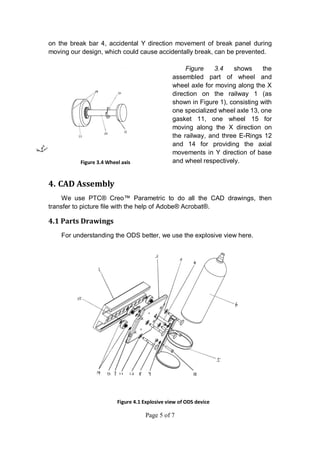
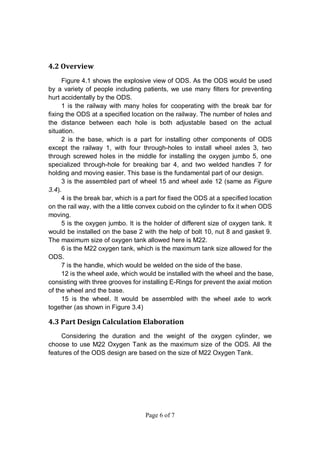
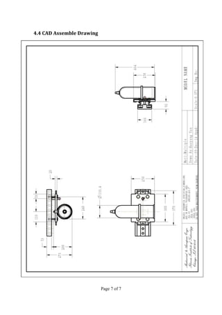
Page 1 of 7
Oxygen Delivery System for Physical Therapy Center
Haotian Meng A20311481
Haoyang Yan A20337136
1. Background
This report describes a kind of Oxygen Delivery System designed for
patients who need Physical Therapy. The name of it is ODS (the abbreviation
of Oxygen Delivery System). The device primarily provides the oxygen support
when patients are doing physical exercise. The ODS device moves on the
railway distributed along the walls, and equipped with brakes. Every ODS
device can hold a uniform 4L or 6L medical Oxygen bottle, as designing an
original oxygen supply system is not practical and economical.
1.1 Target customer
Target patients can be a variety of people, such as the elderly,
brain-injured patients, the recovering stroke, cardiac and spinal injury patients
and whoever need oxygen supply during exercise.
1.2 Necessity of device
Patent US 8191551 B2 is one kind of existing oxygen delivery system.
The advantage of it is that the quality of oxygen can be well preserved.
However, the existing oxygen delivery system is more expensive, heavy to
move, and unfriendly-using for patients. And it is difficult to set up for a therapy
center, for the ceiling is usually decorated with air-conditioners and lights.
Additionally, it is impossible for a couple of patients to use it at the same time.
These disadvantages can discourage the patients to make enough exercise
and thus lead to patients’ weakness.
1.3 Context of device
The goal of the present Oxygen Device System is to improve the condition
of oxygen delivery and make it comfortable and friendly for the patients to use
it mostly by themselves. And the patients are enabled to move with the Oxygen
Device System device freely to most corners of the room.
Another purpose of the Oxygen Device System is to reduce the cost of
purchasing and maintain the Oxygen-generating machine, and make it
possible for a considerable number of patents to using the Oxygen Device
System in a 20×20 foot space at the same time. Furthermore, the Oxygen
Device System is set up according to the origin condition of the Therapy
Exercise room, which can be accepted by most hospitals and therapy center.
Page 2 of 7
2. Description of Invention
2.1 Originality and design process
The first version of Oxygen Device System is designed to set up all the
devices on the ceiling. However, the condition of the ceiling of every therapy
center is different from each other. Furthermore, the decoration will be
time-wasting and difficult for some therapy center.
Thus, the current version of Oxygen Device System is designed to move
on the rail way, distributed along the wall and parallel with the ground. There
will be other distribution depending on the recovering centers’ demands.
2.2 Device operation and therapy process
The ODS device can be easily controlled by human power by using
wheels to move along the railways. For the shelf and the Oxygen cylinder can
be assembled, the patient can check the Oxygen cylinders every time while
using, and select one or replace one when necessary. After choosing one
ODS device, the patient can hold the handle, and move it to the position near
the exercise equipment. By using the railway, the ODS devices can move
stably and with little resistance. And the brakes make it stable when the
patients want to fix an ODS device on a certain position.
The Figure 2.1 shows the normal distribution of the railway. The railway
distribution can be changed depending on the exercise equipment.
With the stable and friendly-used
ODS device, the patients are supplied
with oxygen by wearing pipe oxygen
mask while exercising, such as
running on a running machine to
recover cardiopulmonary function,
weight lifting to strengthen certain part
of the body, using walkers to do
recovery exercise and even using it
during the physical examination.
As it mentioned, comparing with
the existing devices, the ODS device
can be comfortably moved to the
exercise machines, and both patients
and therapists could operate it.
Furthermore, as the resource of
oxygen is the oxygen cylinder which is
economical and easily available, the
maintenance of the ODS is cheaper
and simpler than the existing device. Figure 2.1 Railway distribution
Page 3 of 7
3. Claim and Drawings
3.1 Claim
The Oxygen Delivery System (ODS) for patients who need Physical
Therapy that allows multiple patients to walk and exercise in a 20 x 20 foot
space. The ODS comprising:
1. An E shaped railway (Label 1) with holes for break bar installed on the
vertical wall for allowing movement along horizontal direction;
2. A base (Label 2) would be parallel with the railway for installing wheel
axles and oxygen jumbo, the base would also include a specialized
hole for installing the break bar with a little convex cuboid.
3. A wheel axis (Label 3) is designed with 3 grooves to set 3 E-rings
(Label 12 and 14), so they can fix the wheel and base on the direction
along the wheel axis (Y direction).
4. A brake bar (Label 4) is equipped with the base and move vertically to
the base. The a little convex cuboid is designed on the brake bar so it
can fix the base by rotate and fit in the holes on the E shaped railway.
The ODS device of claim 1 set up along the wall, parallel with the ground,
which is responsible for maintaining the motion direction of the whole system.
The ODS device of claim 2 loads most weight of the oxygen cylinder, and
responsible for the handle and control of the ODS device.
The ODS device of claim 3 is the connection parts between claim 1 and 2.
Equipped with wheels and E-rings, the wheel axis enable ODS device move
stably on the railway, and also transfer the weight of ODS device to the wheels
on the railway.
The ODS devise of claim 4 on the base fit the holes on the claim 1, for the
operators to fix the ODS device while using it.
Drawings and detailed explanations of each component of ODS device is
followed in next part.
Page 4 of 7
3.2 Drawings and detailed explanations
Figure 3.1 is the 3D view of
the ODS, where 1 is the railway
that would be installed on the wall
with wall anchors; 2 is the base; 3
is assemble of wheel and wheel
axle which would be shown in
Figure 3.4; 4 is the break bar; 5 is
the oxygen jumbo (holder) and 6
is the oxygen tank.
Figure 3.2 shows the situation
when the ODS needs to be fixed on
specified location (the oxygen jumbo 5
and the oxygen tank 6 are not shown
here). For fixing the device, rotating the
brake bar 4 about 90 degrees in
clockwise direction and pushing it along
the Y direction into the hole on the
railway, then the whole system would
be kept at the specified location.
Figure 3.3 shows the
situation when the ODS needs to
be moved. For moving the device,
rotating the breaking panel 4
about 90 degrees in counter
clockwise direction and pulling it
along the Y direction out of the
hole on the railway, so the whole
system can move along the X
direction as the double-headed
arrow shown in this figure With
the help of a little convex cuboid
Figure 3.1 ODS device
Figure 3.2 Fastening View
Figure 3.3 Unlocking view
Page 5 of 7
on the break bar 4, accidental Y direction movement of break panel during
moving our design, which could cause accidentally break, can be prevented.
Figure 3.4 shows the
assembled part of wheel and
wheel axle for moving along the X
direction on the railway 1 (as
shown in Figure 1), consisting with
one specialized wheel axle 13, one
gasket 11, one wheel 15 for
moving along the X direction on
the railway, and three E-Rings 12
and 14 for providing the axial
movements in Y direction of base
and wheel respectively.
4. CAD Assembly
We use PTC® Creo™ Parametric to do all the CAD drawings, then
transfer to picture file with the help of Adobe® Acrobat®.
4.1 Parts Drawings
For understanding the ODS better, we use the explosive view here.
Figure 3.4 Wheel axis
Figure 4.1 Explosive view of ODS device
Page 6 of 7
4.2 Overview
Figure 4.1 shows the explosive view of ODS. As the ODS would be used
by a variety of people including patients, we use many filters for preventing
hurt accidentally by the ODS.
1 is the railway with many holes for cooperating with the break bar for
fixing the ODS at a specified location on the railway. The number of holes and
the distance between each hole is both adjustable based on the actual
situation.
2 is the base, which is a part for installing other components of ODS
except the railway 1, with four through-holes to install wheel axles 3, two
through screwed holes in the middle for installing the oxygen jumbo 5, one
specialized through-hole for breaking bar 4, and two welded handles 7 for
holding and moving easier. This base is the fundamental part of our design.
3 is the assembled part of wheel 15 and wheel axle 12 (same as Figure
3.4).
4 is the break bar, which is a part for fixed the ODS at a specified location
on the rail way, with the a little convex cuboid on the cylinder to fix it when ODS
moving.
5 is the oxygen jumbo. It is the holder of different size of oxygen tank. It
would be installed on the base 2 with the help of bolt 10, nut 8 and gasket 9.
The maximum size of oxygen tank allowed here is M22.
6 is the M22 oxygen tank, which is the maximum tank size allowed for the
ODS.
7 is the handle, which would be welded on the side of the base.
12 is the wheel axle, which would be installed with the wheel and the base,
consisting with three grooves for installing E-Rings for prevent the axial motion
of the wheel and the base.
15 is the wheel. It would be assembled with the wheel axle to work
together (as shown in Figure 3.4)
4.3 Part Design Calculation Elaboration
Considering the duration and the weight of the oxygen cylinder, we
choose to use M22 Oxygen Tank as the maximum size of the ODS. All the
features of the ODS design are based on the size of M22 Oxygen Tank.
Page 7 of 7
4.4 CAD Assemble Drawing

445 Reprot final 正式上交

  • 1.
    Page 1 of7 Oxygen Delivery System for Physical Therapy Center Haotian Meng A20311481 Haoyang Yan A20337136 1. Background This report describes a kind of Oxygen Delivery System designed for patients who need Physical Therapy. The name of it is ODS (the abbreviation of Oxygen Delivery System). The device primarily provides the oxygen support when patients are doing physical exercise. The ODS device moves on the railway distributed along the walls, and equipped with brakes. Every ODS device can hold a uniform 4L or 6L medical Oxygen bottle, as designing an original oxygen supply system is not practical and economical. 1.1 Target customer Target patients can be a variety of people, such as the elderly, brain-injured patients, the recovering stroke, cardiac and spinal injury patients and whoever need oxygen supply during exercise. 1.2 Necessity of device Patent US 8191551 B2 is one kind of existing oxygen delivery system. The advantage of it is that the quality of oxygen can be well preserved. However, the existing oxygen delivery system is more expensive, heavy to move, and unfriendly-using for patients. And it is difficult to set up for a therapy center, for the ceiling is usually decorated with air-conditioners and lights. Additionally, it is impossible for a couple of patients to use it at the same time. These disadvantages can discourage the patients to make enough exercise and thus lead to patients’ weakness. 1.3 Context of device The goal of the present Oxygen Device System is to improve the condition of oxygen delivery and make it comfortable and friendly for the patients to use it mostly by themselves. And the patients are enabled to move with the Oxygen Device System device freely to most corners of the room. Another purpose of the Oxygen Device System is to reduce the cost of purchasing and maintain the Oxygen-generating machine, and make it possible for a considerable number of patents to using the Oxygen Device System in a 20×20 foot space at the same time. Furthermore, the Oxygen Device System is set up according to the origin condition of the Therapy Exercise room, which can be accepted by most hospitals and therapy center.
  • 2.
    Page 2 of7 2. Description of Invention 2.1 Originality and design process The first version of Oxygen Device System is designed to set up all the devices on the ceiling. However, the condition of the ceiling of every therapy center is different from each other. Furthermore, the decoration will be time-wasting and difficult for some therapy center. Thus, the current version of Oxygen Device System is designed to move on the rail way, distributed along the wall and parallel with the ground. There will be other distribution depending on the recovering centers’ demands. 2.2 Device operation and therapy process The ODS device can be easily controlled by human power by using wheels to move along the railways. For the shelf and the Oxygen cylinder can be assembled, the patient can check the Oxygen cylinders every time while using, and select one or replace one when necessary. After choosing one ODS device, the patient can hold the handle, and move it to the position near the exercise equipment. By using the railway, the ODS devices can move stably and with little resistance. And the brakes make it stable when the patients want to fix an ODS device on a certain position. The Figure 2.1 shows the normal distribution of the railway. The railway distribution can be changed depending on the exercise equipment. With the stable and friendly-used ODS device, the patients are supplied with oxygen by wearing pipe oxygen mask while exercising, such as running on a running machine to recover cardiopulmonary function, weight lifting to strengthen certain part of the body, using walkers to do recovery exercise and even using it during the physical examination. As it mentioned, comparing with the existing devices, the ODS device can be comfortably moved to the exercise machines, and both patients and therapists could operate it. Furthermore, as the resource of oxygen is the oxygen cylinder which is economical and easily available, the maintenance of the ODS is cheaper and simpler than the existing device. Figure 2.1 Railway distribution
  • 3.
    Page 3 of7 3. Claim and Drawings 3.1 Claim The Oxygen Delivery System (ODS) for patients who need Physical Therapy that allows multiple patients to walk and exercise in a 20 x 20 foot space. The ODS comprising: 1. An E shaped railway (Label 1) with holes for break bar installed on the vertical wall for allowing movement along horizontal direction; 2. A base (Label 2) would be parallel with the railway for installing wheel axles and oxygen jumbo, the base would also include a specialized hole for installing the break bar with a little convex cuboid. 3. A wheel axis (Label 3) is designed with 3 grooves to set 3 E-rings (Label 12 and 14), so they can fix the wheel and base on the direction along the wheel axis (Y direction). 4. A brake bar (Label 4) is equipped with the base and move vertically to the base. The a little convex cuboid is designed on the brake bar so it can fix the base by rotate and fit in the holes on the E shaped railway. The ODS device of claim 1 set up along the wall, parallel with the ground, which is responsible for maintaining the motion direction of the whole system. The ODS device of claim 2 loads most weight of the oxygen cylinder, and responsible for the handle and control of the ODS device. The ODS device of claim 3 is the connection parts between claim 1 and 2. Equipped with wheels and E-rings, the wheel axis enable ODS device move stably on the railway, and also transfer the weight of ODS device to the wheels on the railway. The ODS devise of claim 4 on the base fit the holes on the claim 1, for the operators to fix the ODS device while using it. Drawings and detailed explanations of each component of ODS device is followed in next part.
  • 4.
    Page 4 of7 3.2 Drawings and detailed explanations Figure 3.1 is the 3D view of the ODS, where 1 is the railway that would be installed on the wall with wall anchors; 2 is the base; 3 is assemble of wheel and wheel axle which would be shown in Figure 3.4; 4 is the break bar; 5 is the oxygen jumbo (holder) and 6 is the oxygen tank. Figure 3.2 shows the situation when the ODS needs to be fixed on specified location (the oxygen jumbo 5 and the oxygen tank 6 are not shown here). For fixing the device, rotating the brake bar 4 about 90 degrees in clockwise direction and pushing it along the Y direction into the hole on the railway, then the whole system would be kept at the specified location. Figure 3.3 shows the situation when the ODS needs to be moved. For moving the device, rotating the breaking panel 4 about 90 degrees in counter clockwise direction and pulling it along the Y direction out of the hole on the railway, so the whole system can move along the X direction as the double-headed arrow shown in this figure With the help of a little convex cuboid Figure 3.1 ODS device Figure 3.2 Fastening View Figure 3.3 Unlocking view
  • 5.
    Page 5 of7 on the break bar 4, accidental Y direction movement of break panel during moving our design, which could cause accidentally break, can be prevented. Figure 3.4 shows the assembled part of wheel and wheel axle for moving along the X direction on the railway 1 (as shown in Figure 1), consisting with one specialized wheel axle 13, one gasket 11, one wheel 15 for moving along the X direction on the railway, and three E-Rings 12 and 14 for providing the axial movements in Y direction of base and wheel respectively. 4. CAD Assembly We use PTC® Creo™ Parametric to do all the CAD drawings, then transfer to picture file with the help of Adobe® Acrobat®. 4.1 Parts Drawings For understanding the ODS better, we use the explosive view here. Figure 3.4 Wheel axis Figure 4.1 Explosive view of ODS device
  • 6.
    Page 6 of7 4.2 Overview Figure 4.1 shows the explosive view of ODS. As the ODS would be used by a variety of people including patients, we use many filters for preventing hurt accidentally by the ODS. 1 is the railway with many holes for cooperating with the break bar for fixing the ODS at a specified location on the railway. The number of holes and the distance between each hole is both adjustable based on the actual situation. 2 is the base, which is a part for installing other components of ODS except the railway 1, with four through-holes to install wheel axles 3, two through screwed holes in the middle for installing the oxygen jumbo 5, one specialized through-hole for breaking bar 4, and two welded handles 7 for holding and moving easier. This base is the fundamental part of our design. 3 is the assembled part of wheel 15 and wheel axle 12 (same as Figure 3.4). 4 is the break bar, which is a part for fixed the ODS at a specified location on the rail way, with the a little convex cuboid on the cylinder to fix it when ODS moving. 5 is the oxygen jumbo. It is the holder of different size of oxygen tank. It would be installed on the base 2 with the help of bolt 10, nut 8 and gasket 9. The maximum size of oxygen tank allowed here is M22. 6 is the M22 oxygen tank, which is the maximum tank size allowed for the ODS. 7 is the handle, which would be welded on the side of the base. 12 is the wheel axle, which would be installed with the wheel and the base, consisting with three grooves for installing E-Rings for prevent the axial motion of the wheel and the base. 15 is the wheel. It would be assembled with the wheel axle to work together (as shown in Figure 3.4) 4.3 Part Design Calculation Elaboration Considering the duration and the weight of the oxygen cylinder, we choose to use M22 Oxygen Tank as the maximum size of the ODS. All the features of the ODS design are based on the size of M22 Oxygen Tank.
  • 7.
    Page 7 of7 4.4 CAD Assemble Drawing