Download as PDF, PPTX


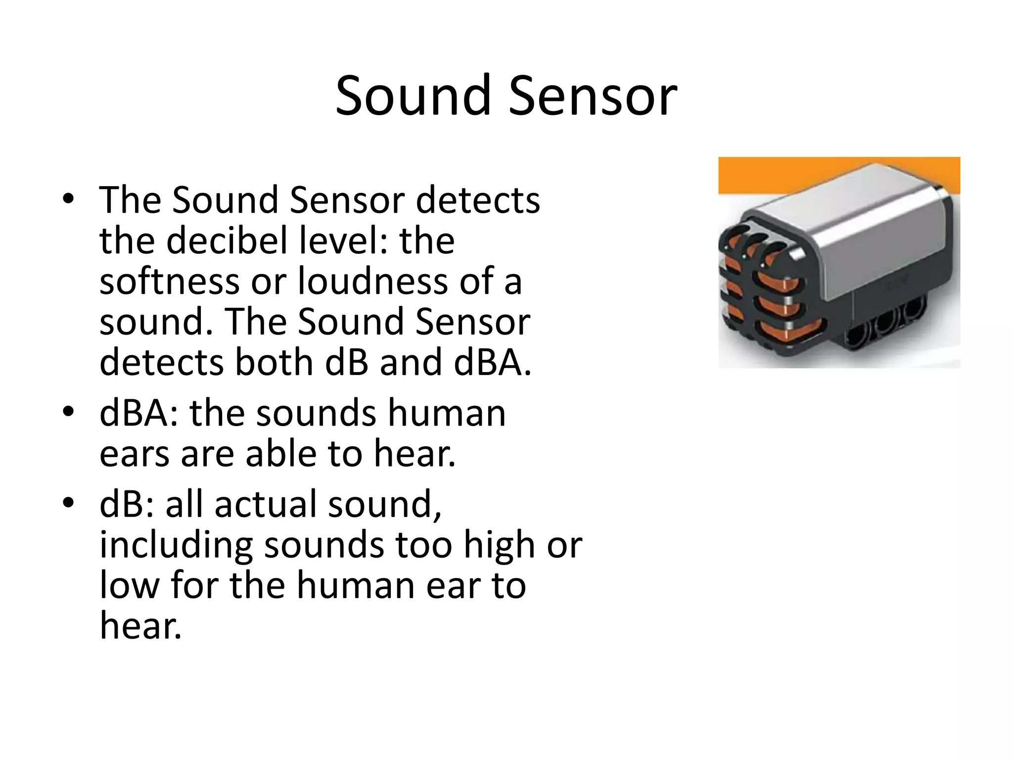
![• The Sound Sensor can measure sound pressure levels up to 90 dB
– about the level of a lawnmower.
• Sound sensor readings on the LEGO® MINDSTORMS® NXT
are displayed in the percentage [%] of sound the sensor is
capable of reading.
• For comparison, 4-5% is like a silent living room and 5-10% is
about the level of someone talking some distance away.
• From 10-30% is normal conversation close to the sensor or music
played at a normal level and 30-100% represents a range from
people shouting to music playing at high volumes.
• These ranges are assuming a distance of about 1 meter between
the sound source and the Sound Sensor.](https://image.slidesharecdn.com/chapter5designprojects-141116132322-conversion-gate01/75/Chapter-5-design-projects-69-2048.jpg)


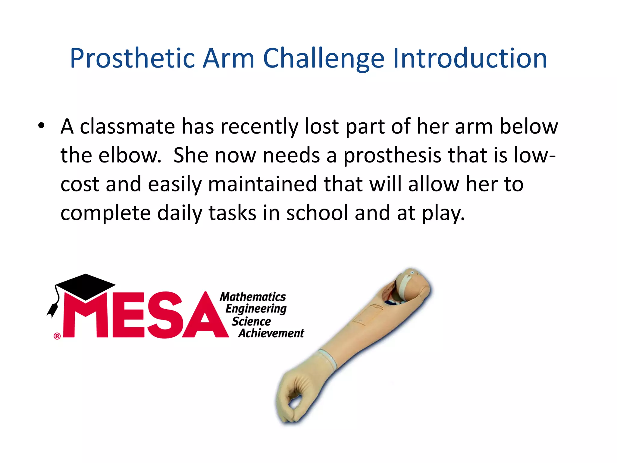
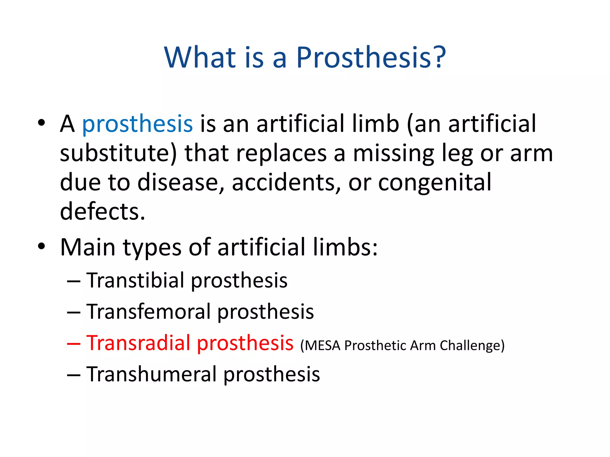
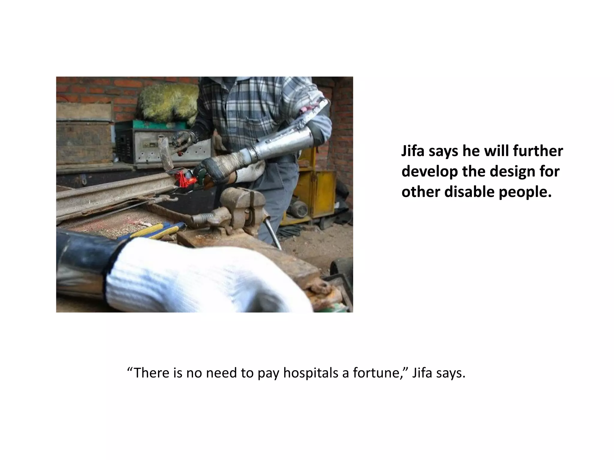
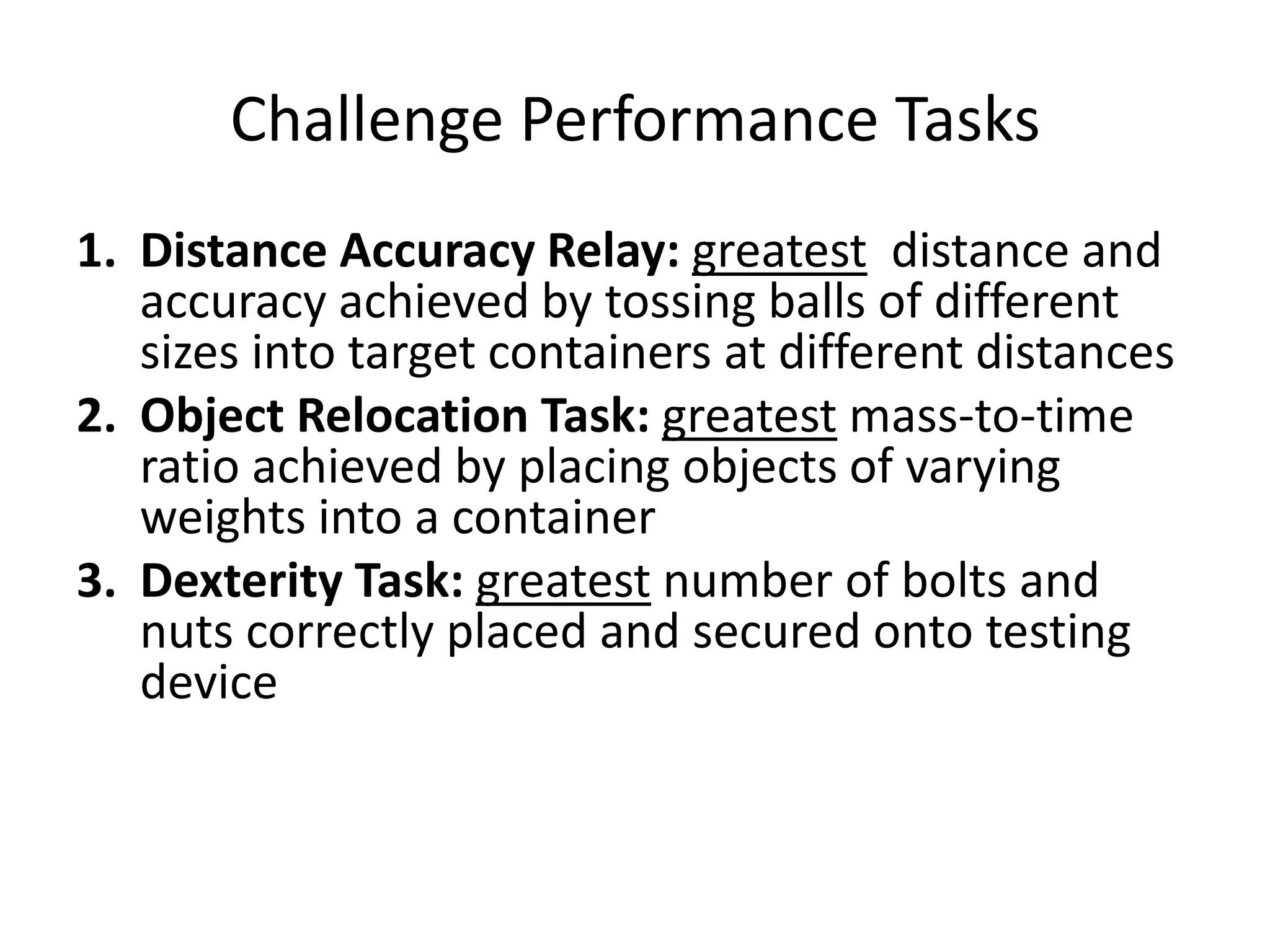
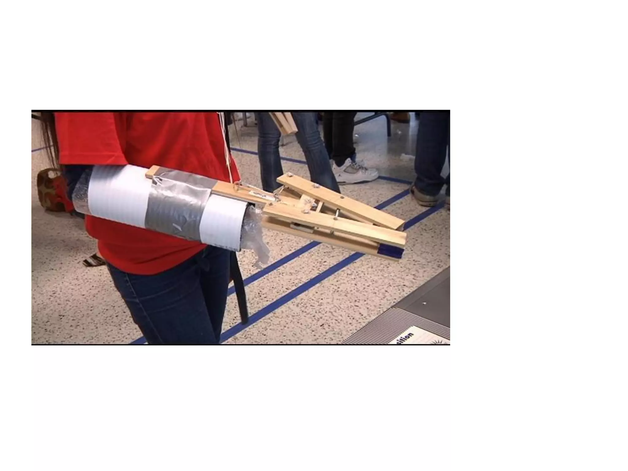
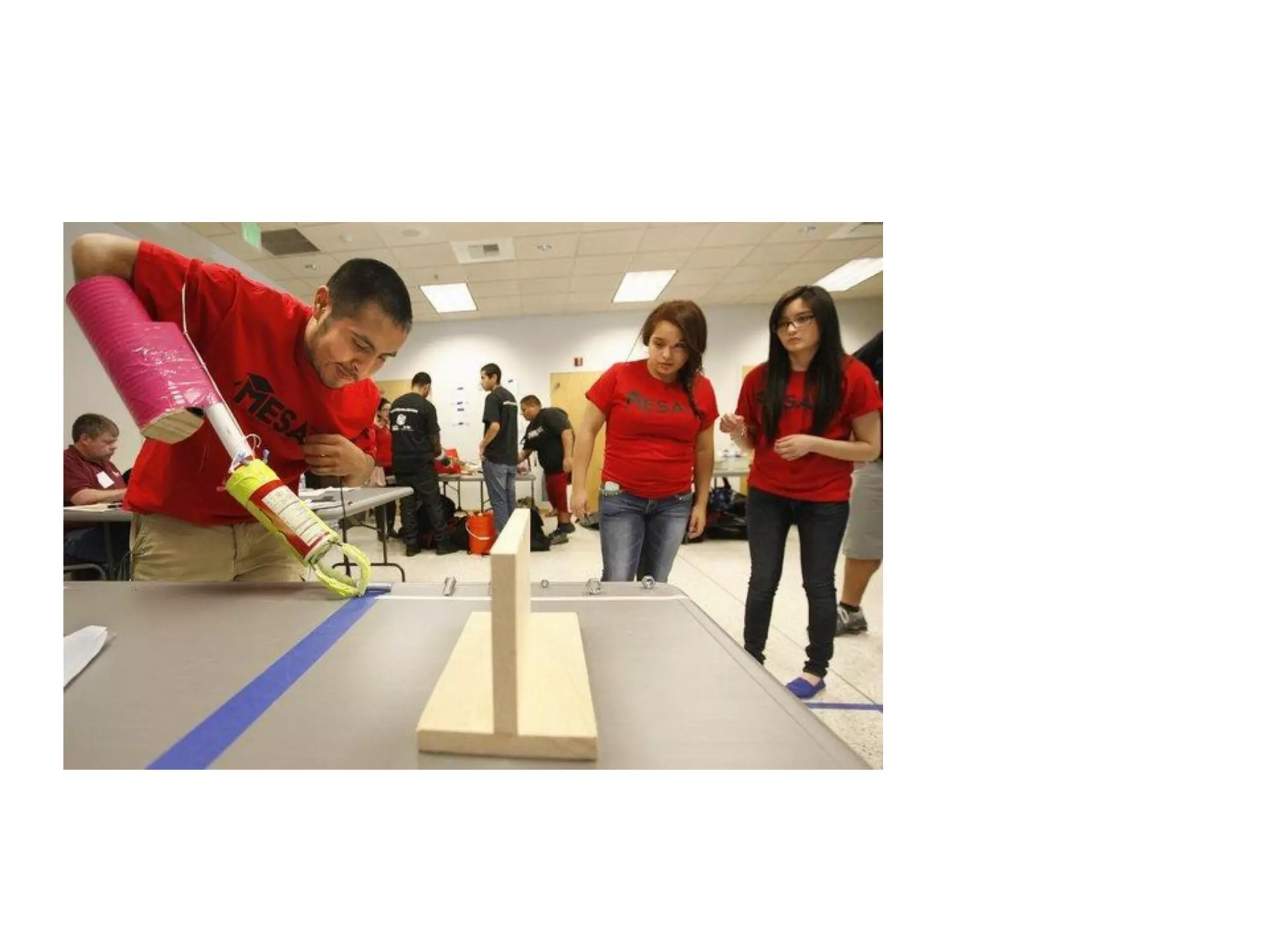
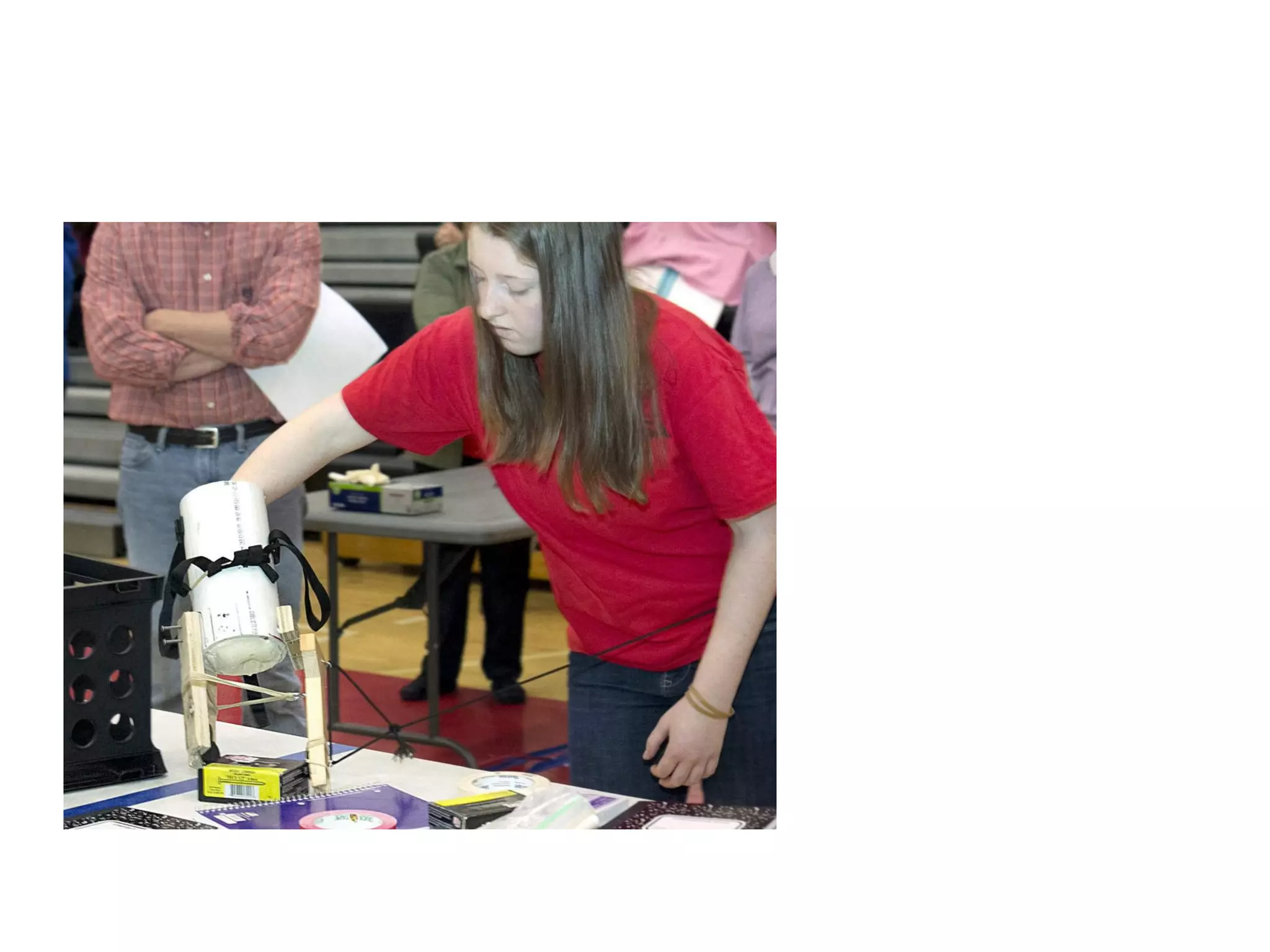
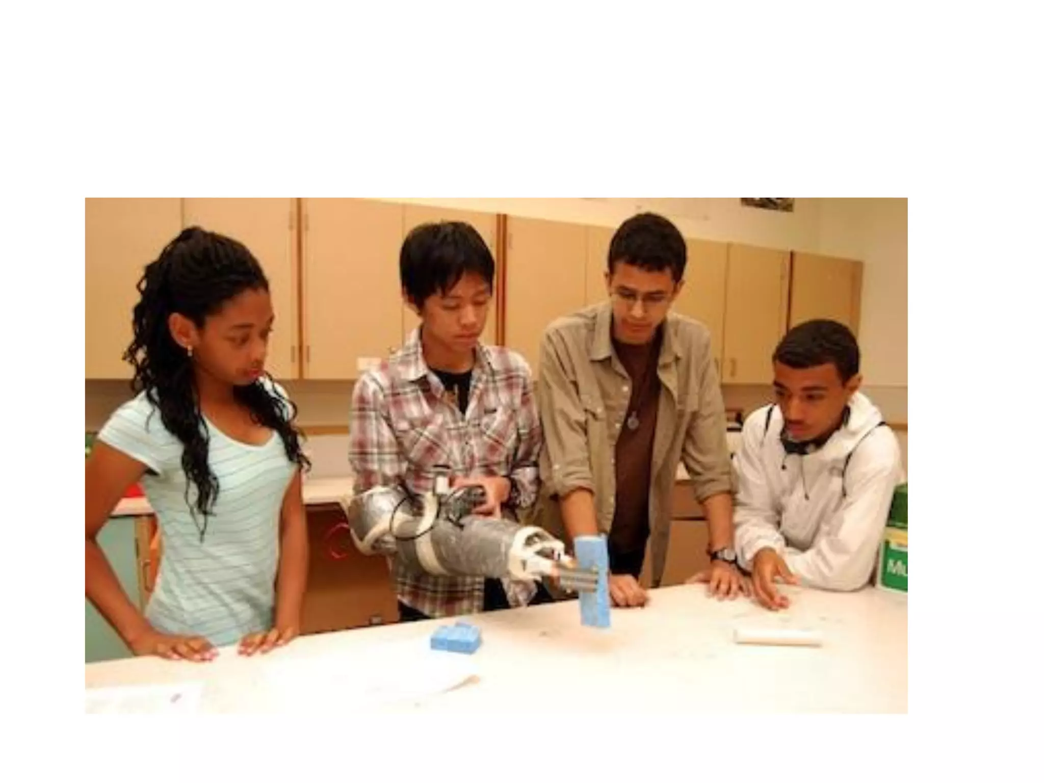
The document provides information about designing a prosthetic arm for a classmate who recently lost part of her arm below the elbow. It outlines the design challenge which is to create a low-cost prosthetic device that allows her to perform daily tasks. The device must meet criteria such as costing less than $40 and weighing less than 3kg. It also describes the performance tasks the device will be evaluated on, including tossing balls into targets at various distances and placing objects in a container. Background research activities are suggested to inform the design such as patent searches, reverse engineering, and user interviews.


