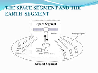
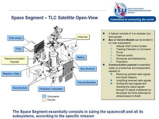
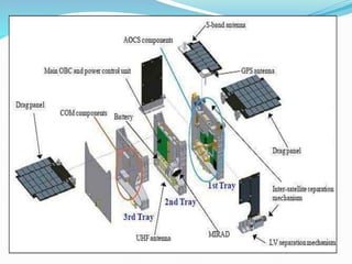
The document discusses the key components and subsystems that make up the space segment of a satellite system. It describes:
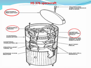
1) The main components of a satellite including the payload (service equipment), bus (vehicle), and subsystems that provide power, attitude control, thermal control, and telemetry/command functions.
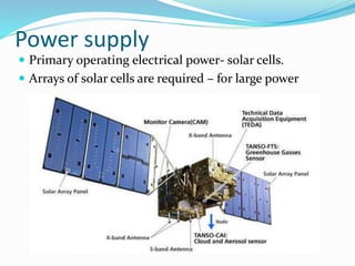
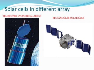
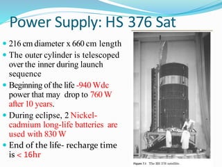
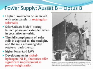
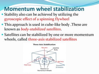
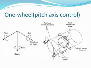
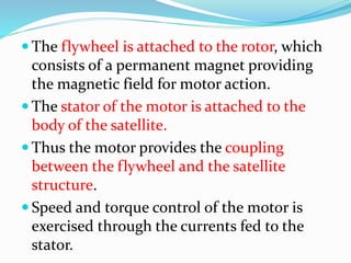
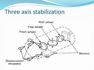
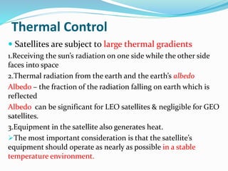
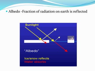
2) Specific subsystems like transponders, solar cells and batteries for power supply, momentum wheels and gas jets for attitude control, and thermal blankets/shields for thermal control.
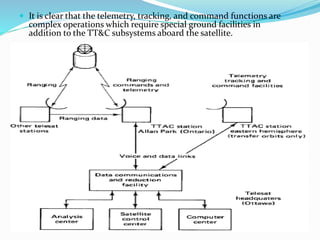
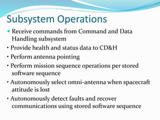
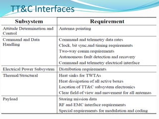
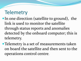
3) The telemetry, tracking and control subsystem provides communication between the satellite and ground stations for monitoring and control.