Download to read offline
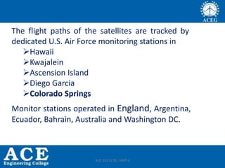
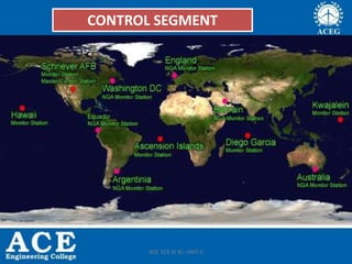
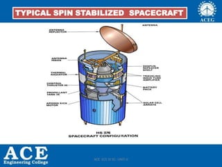
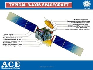
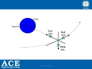
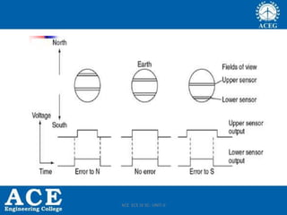
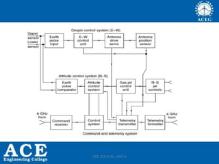
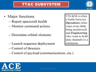
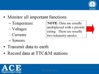
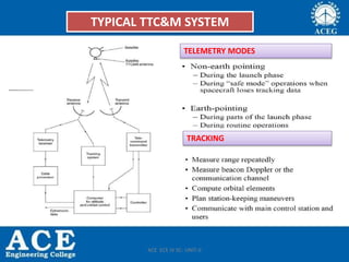

The document describes the GPS system's control and user segments, detailing the U.S. Army's monitoring capabilities through a master control station and multiple dedicated monitor stations worldwide. It highlights the recent addition of monitor stations to improve satellite tracking and precision data calculation, with plans for further enhancements in monitoring. Additionally, it covers the technical aspects of spacecraft subsystems, communication methodologies, and challenges related to satellite link design under varying environmental conditions.