Downloaded 383 times

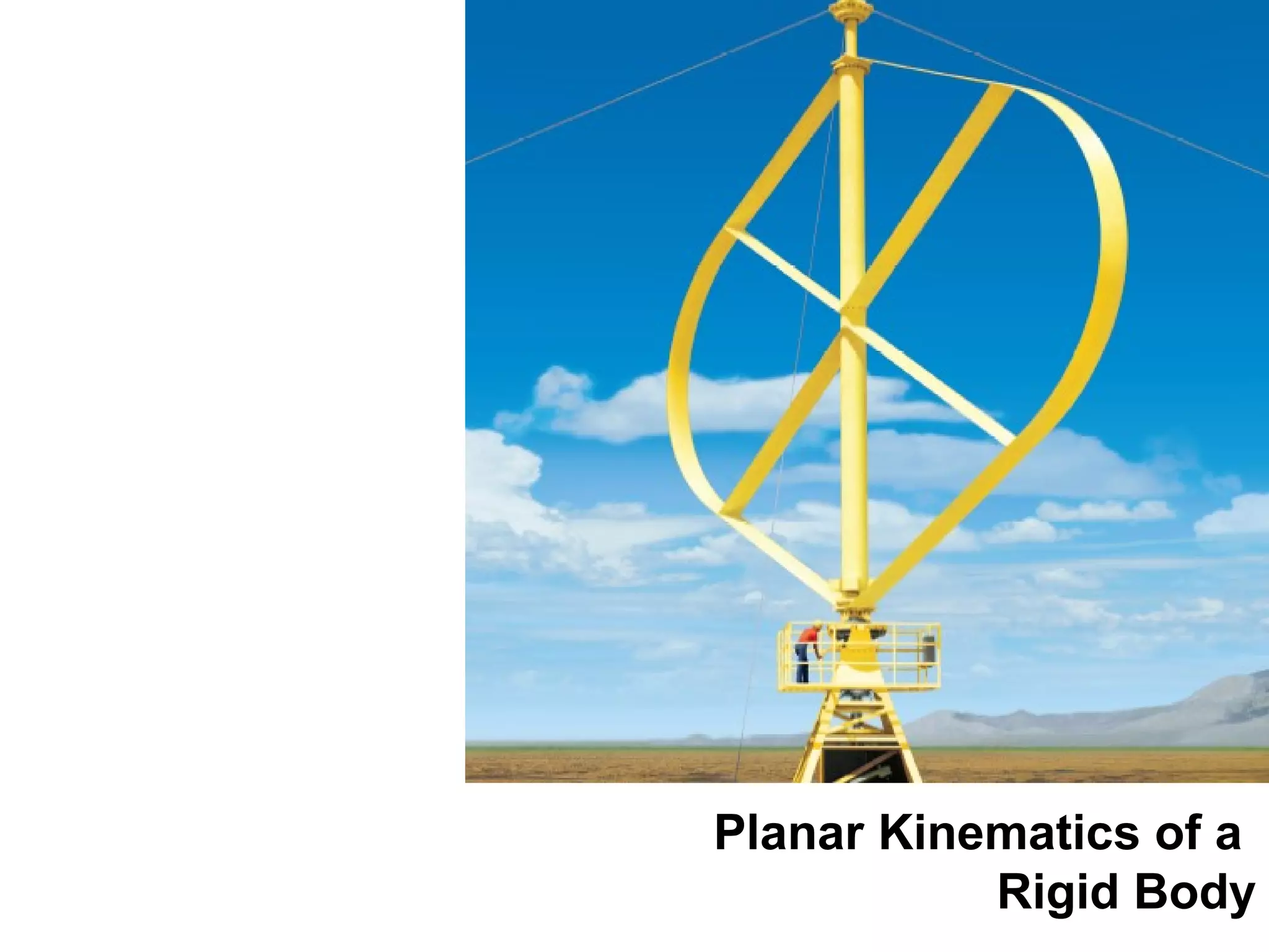
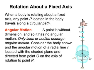
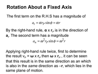

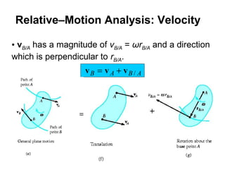
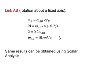
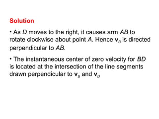
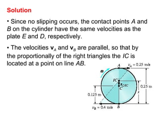
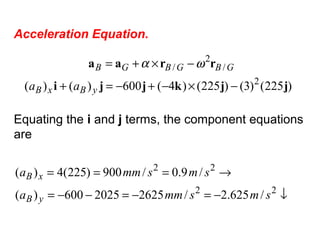
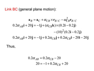
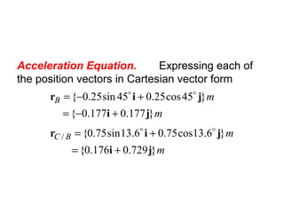
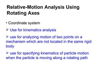
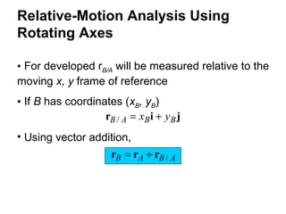
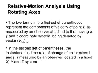
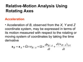
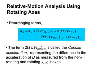
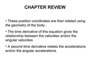
![Velocity Equation.
ijji
jikji
rvv
45cos2.045sin2.02
)]45cos2.045sin2.0([2
/
ωω
ω
ω
++−=
−×+−=
×+=
B
B
ABAB
v
v
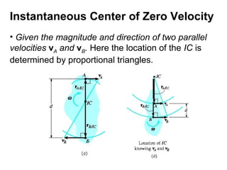
Equating the i and j components gives
→=
=
+−==
smv
srad
v
B
B
/2
/1.14
45sin2.02045cos2.0
ω
ωω
](https://image.slidesharecdn.com/dynamicslecture5-140613051813-phpapp01/85/Dynamics-lecture5-72-320.jpg)
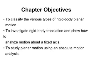
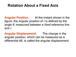
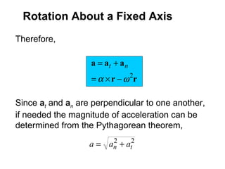
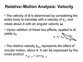
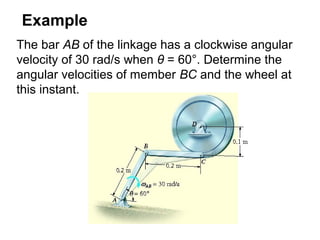
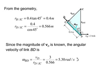
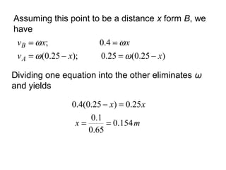
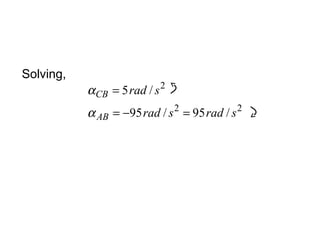
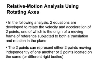
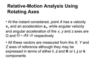
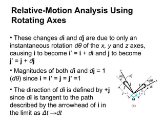
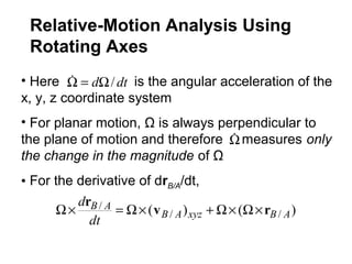
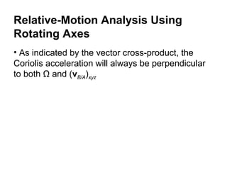
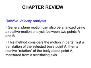
![Velocity Equation.
ijiji
jikiji
rvv
50.750.72)()(
)]5.05.0()15(2)()(
/
++=+
+−×−+=+
×+=
yAxA
yAxA
ABBA
vv
vv
ω
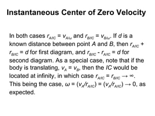
So that
smv
smv
yA
xA
/50.7)(
/50.950.72)(
=
=+=](https://image.slidesharecdn.com/dynamicslecture5-140613051813-phpapp01/85/Dynamics-lecture5-75-320.jpg)
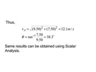
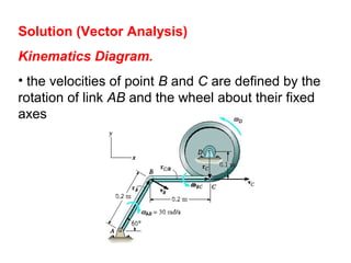
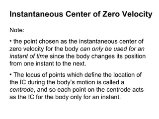
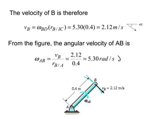
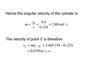
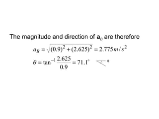

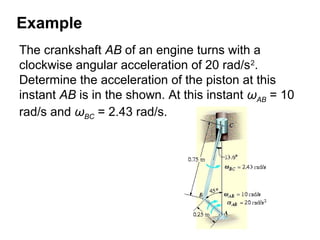
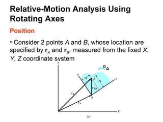
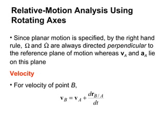
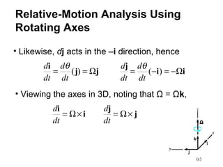
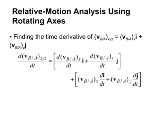
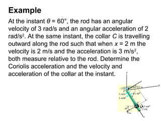
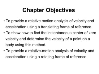
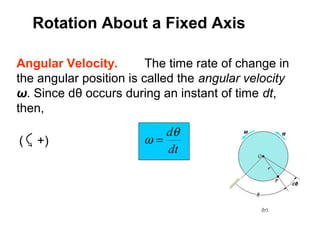
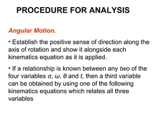
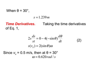
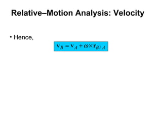
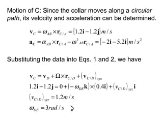
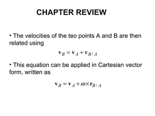
![The velocity and acceleration of the collar are
determined by substituting the data in the previous
2 equations and evaluating the cross products,
which yields,
{ }
[ ]
{ } 2
////
//
/4.1220.1
3)2()3(2)2.0()3()3()2.0()2(0
)()(2)(
/6.02
2)2.0()3(0
)(
sm
sm
xyzOCxyzOCOCOCOC
xyzOCOCOC
ji
iikikkik
avrraa
ji
iik
vrvv
−=
+×−+×−×−+×−+=
+×Ω+×Ω×Ω+×Ω+=
−=
+×−+=
+×Ω+=
](https://image.slidesharecdn.com/dynamicslecture5-140613051813-phpapp01/85/Dynamics-lecture5-171-320.jpg)
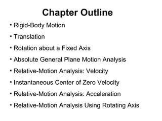
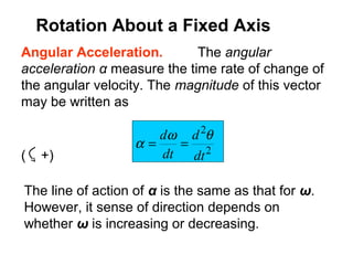
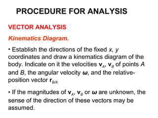
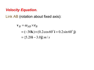
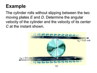
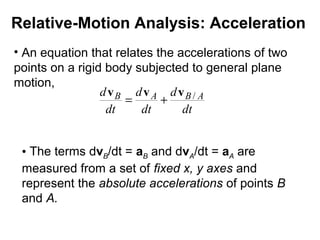
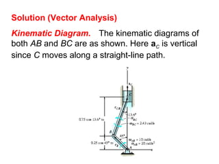
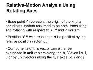
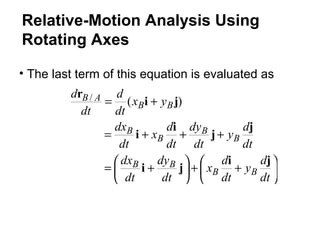
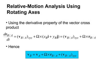
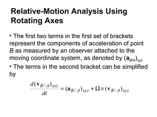
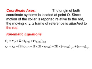
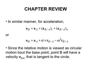
![( ) ( ) ( )
( ) ( ) ( ) ( ) ( )[ ]
( ) ( ) ( )
( )
22
2
/
/
////
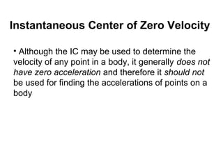
/5/5
/6.1
2.132
4.0334.002.52
2
sradsrad
sma
DE
xyzDC
xyzDC
DE
xyzDCxyzDCDCDCDC
=−=
=
+×−+
×−×−+×−+=−−
+×Ω+×Ω×Ω+×Ω+=
•
α
α
iaik
ikkikji
avrraa](https://image.slidesharecdn.com/dynamicslecture5-140613051813-phpapp01/85/Dynamics-lecture5-176-320.jpg)
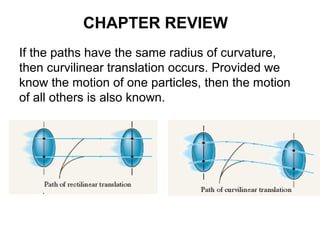
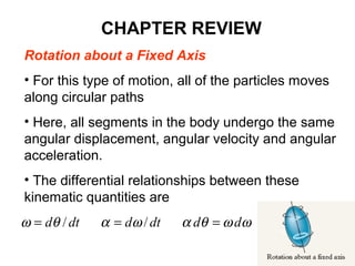

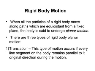
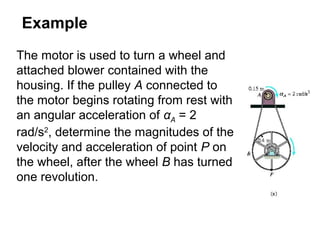
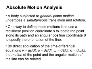
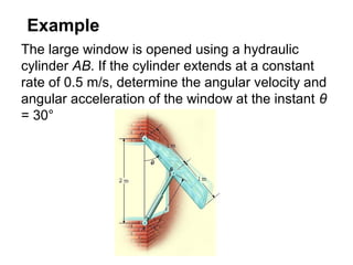
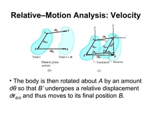
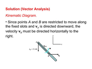
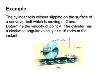
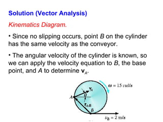
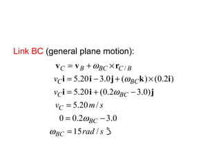
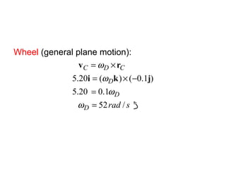
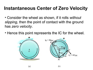
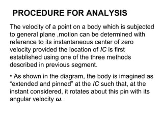
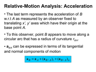
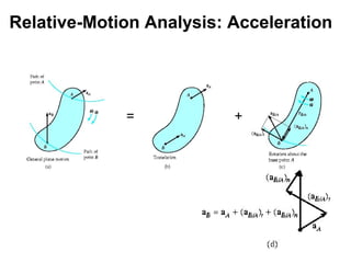
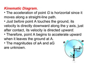
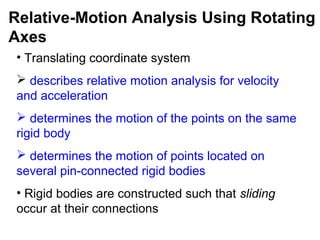
This document provides an overview of planar kinematics of rigid body motion. It describes three types of planar rigid body motion: translation, rotation about a fixed axis, and general plane motion. Translation can be rectilinear or curvilinear. Rotation about a fixed axis involves angular position, velocity, acceleration, and the motion of a point on the rotating body. General plane motion is a combination of translation and rotation. Formulas are provided for analyzing velocity and acceleration during these different types of motion. Examples are also given to demonstrate how to apply the kinematic equations.


