Download to read offline
![Er. Manoj Kumar. Int. Journal of Engineering Research and Application www.ijera.com
ISSN : 2248-9622, Vol. 7, Issue 3, ( Part -2) March 2017, pp.92-98
www.ijera.com DOI: 10.9790/9622- 0703029298 92 | P a g e
Duplex 2209 Weld Overlay by ESSC Process
Er. Manoj Kumar1
, Dr. Abhishek Kamboj2
1
M.tech research Scholar,Haryana Engineering College
2
Associate Professor, Haryana Engineering College
ABSTRACT
In the modern world of industrialization the wear is eating metal assets worth millions of dollars per year. The
wear is in the form of corrosion, erosion, abrasion etc. which occur in the process industries like oil & gas,
refineries, cement plants, steel plants, shipping and offshore working structures. The equipments like pressure
vessels, heat exchangers, hydro processing reactors which very often work at elevated temperatures face
corrosion in the internal diameter. Duplex 2209 weld overlay on ferrous material is developed for high corrosion
resistance properties and having high productivity by Electroslag strip cladding process due to its less dilution
~10% as compared to SMAW , GTAW or FCAW process. Because of Low Dilution ~10% undiluted chemistry
can be achieved with single layer as compared to other weld overlay processes. The facility was developed in-
house to carry out weld overlay by ESSC and Testing.
I. INTRODUCTION
Duplex stainless steel are called “Duplex”
because they have a two-phase microstructure
consisting of grains of ferritic and austenitic
stainless steel. When duplex stainless steel is
melted it solidifies from the liquid phase to
completely ferritic structure. As the material cools
through temp above about 1040 deg C to room
temperature, about half of the ferritic grains
transfer to austenitic grains. The result is a
microstructure of roughly 50% austenite and 50%
ferrite. This is accomplished by increasing
Chromium and decreasing Ni as compared to ASS
grades & by adding Nitrogen (a strong austenite
promoter) to speed the rate up of austenite
formation during cooling[1].
A minimum 10.5% Chromium is
necessary to form a stable Chromium passive film
that is sufficient to protect steel against
atmospheric corrosion. The corrosion resistance of
SS increases with increasing Chromium content.
Chromium is a ferrite former, meaning that the
addition of Chromium promotes the BCC structure
of iron. At higher Chromium contents, more nickel
is necessary to form an austenite or duplex
structure. Higher Chromium also promotes the
formation of intermetallic phases. Chromium also
increases the oxidation resistance at elevated
temperatures.
Molybdenum acts to support Chromium in
providing pitting corrosion resistance to stainless
steels. When the Chromium content of a SS is at
least 18%,addition of Mo become about three times
as effective as Chromium addition against pitting
and crevice corrosion in Chloride-containing
environment.Molybdenum is a ferrite former and
also increases the tendency of a SS to form
detrimental intermetallic phases.Therefore,it is
restricted to less than about 7.5% in ASS and 4% in
Duplex SS[1,2].
Nitrogen increases the pitting and crevice
corrosion resistance of austenite and Duplex SS. It
also increases strength and is most effective solid
solution strengthening element and low cost
element. The improved toughness of nitrogen
bearing duplex SS is due to their greater austenite
content and reduced intermetallic content. Nitrogen
does not prevent the precipitation of intermetallic
phases but delays the formation of inter- metallics
enough to permit processing and fabrication of
duplex stainless steel. Nitrogen is added to highly
corrosion resistant austenite and duplex stainless
steels that contain high chromium and
molybdenum contents to offset their tendency to
form sigma phase. Nitrogen is the key element,
apart from aiding austenite formation, it plays a
role in partitioning of alloying element Cr,Mo
between ferrite and austenite.
During welding, there is a danger that the
austenite formed from ferrite from heating, will
contain only the low amount of N that was in the
ferrite from which it was formed. if heating time is
sufficient ,Nitrogen can diffuse from the original
austenite to restore equilibrium.But, if the heating
time is too short, the so called secondary austenite
will have low N & therefore lower pitting corrosion
resistance.
Nitrogen helps to alter phase stability ,
making austenite stable to higher temperature,&
this prevents welds from becoming excessively
ferritic and disturbing the desirable 50 to 50
ratio[1,6].
1.1 Characteristics of Duplex stainless steels
Excellent resistance to stress corrosion
cracking
RESEARCH ARTICLE OPEN ACCESS](https://image.slidesharecdn.com/q0703029298-170322083007/85/Duplex-2209-Weld-Overlay-by-ESSC-Process-1-320.jpg)
![Er. Manoj Kumar. Int. Journal of Engineering Research and Application www.ijera.com
ISSN : 2248-9622, Vol. 7, Issue 3, ( Part -2) March 2017, pp.92-98
www.ijera.com DOI: 10.9790/9622- 0703029298 93 | P a g e
Very high mechanical strength
Excellent resistance to pitting and crevice
corrosion
High resistance to general corrosion in a
variety of environments
Low thermal expansion
High resistance to erosion corrosion and
corrosion fatigue
Good weldability
Lower life cycle cost[1]
Duplex stainless steel is having higher
critical crevice corrosion temperature as well as
critical pitting corrosion temperature as compared
to austenitic stainless steel material as shown in
below Fig.1 and Duplex stainless steel is having
lower corrosion rate than austenitic stainless steel
in formic acid Concentration as shown in Fig.2[2,5]
Fig. 1
Fig. 2
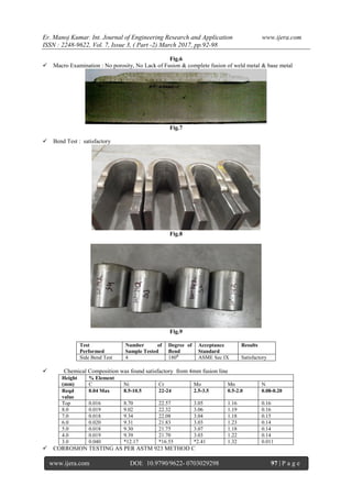
1.2 Chemical Composition of Dupex 2209
Element % Composition
Nickel 8.5-10.5
Chromium 22-24
Molybdenum 2.5-3.5
Carbon 0.04 max
Manganese 0.5-2.0
Sulfur 0.03 max
Silicon 1.0 max
Phosphorous 0.04 max
Table 1
Cladding is a welding process in which a
material with desired properties is deposited on the
surface of a base material. The common C/Mn or
low alloyed inexpensive base metal has mainly a
load carrying function. The deposited sophisticated
material imparts surface properties such as
corrosion resistance; wear resistance, erosion and
pitting etc., to the substrate. To the manufacturer of
pressure vessels, surfacing techniques are getting
more and more important. Components reach sizes
such that their fabrication calls upon the use of clad
materials[3,6].
There are different processes to obtain a clad
material:
Clad plates produced by rolling which are
mostly only available in standardized
dimensions and grades
Explosion clad plates
Clad plates made by welding
Further Clad Plates made by welding can be done
using various techniques:-
Submerged arc welding (Wire electrode)
Submerged arc welding (Twin Wire electrode)
Submerged arc welding (Strip Electrode)
Electro slag strip welding](https://image.slidesharecdn.com/q0703029298-170322083007/85/Duplex-2209-Weld-Overlay-by-ESSC-Process-2-320.jpg)
![Er. Manoj Kumar. Int. Journal of Engineering Research and Application www.ijera.com
ISSN : 2248-9622, Vol. 7, Issue 3, ( Part -2) March 2017, pp.92-98
www.ijera.com DOI: 10.9790/9622- 0703029298 94 | P a g e
Shielded metal arc welding
Flux cored arc welding
Among all the welding processes
submerged arc and electro slag strip cladding offer
maximum deposition rate, better bead
characteristics and trouble free operation using
unsophisticated welding equipments[6,7].
In selecting a particular weld overlay and
cladding system, the following criteria may need to
be considered: Deposit rate (kg/hr), productivity
hardness, corrosion resistance, availability of
consumables with the required metallurgical and
mechanical properties, welding techniques, Quality
of weld & automation technologies.
II. PROCESS DESCRIPTION
The electro slag strip cladding is a
technique, in which a strip electrode is
continuously fed into a shallow layer of electrically
conductive flux. The heat required to melt the strip,
the slag forming flux and the surface layer of the
base metal is generated by resistance heating due to
the welding current flowing through the molten
conductive slag. In relation to the submerged arc
strip cladding, the penetration and hence the
dilution are reduced in electro slag strip cladding
because the absence of arc, typical dilution levels
lying between ~10% [4].The use of a conductive
slag and resistance heating instead of an electric arc
permits higher current densities to be used in ESSC
without increasing penetration. Thus deposition
rates higher than that possible with SASC can be
achieved in ESSC without increasing the degree of
dilution[2,3,4].
The flux used in ESSC contains, in
addition to oxides like Titanium oxide and iron
oxide. A large quantity fluoride of Calcium and
Sodium in order to achieve the required electrical
conductivity. The high Calcium fluoride content in
the flux has been shown to decrease dilution level
and also reduce the oxygen content in the deposited
cladding to a level which is just one third compared
to submerged arc surfacing. Furthermore the
solidification rate of the electroslag weld metal is
lower, facilitating the escape of gases and the rise
of slag particles to the surface. This reduces
porosity and inclusion content[2,3,8].
Fig.3
III. EXPERIMENTATION AND TESTING
Discuss the detail about the experimental data, base metal, filler metal, and welding procedure, welding
parameters of welded specimen and testing.](https://image.slidesharecdn.com/q0703029298-170322083007/85/Duplex-2209-Weld-Overlay-by-ESSC-Process-3-320.jpg)
![Er. Manoj Kumar. Int. Journal of Engineering Research and Application www.ijera.com
ISSN : 2248-9622, Vol. 7, Issue 3, ( Part -2) March 2017, pp.92-98
www.ijera.com DOI: 10.9790/9622- 0703029298 98 | P a g e
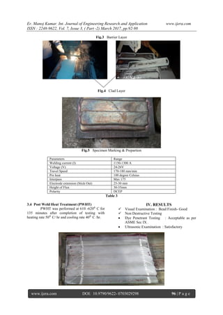
Result observed: satisfactory
Acceptance criteria
The corrosion rate is calculated in
accordance with the weight loss & it should be less
than 10 mdd( milligrams per square decimeter per
day)
Initial weight of specimen : 43.161g
Weight after 24 hours : 43.1603 g
Weight loss : 0.0007 g (0.70 mg)
Corrosion rate : 2.2150 mdd (acceptable)
Fig.10 Corrosion Specimen (ASTM 923 METHOD
C)
V. CONCLUSION
Typical to weld Duplex 2209 welded
successfully meeting the requirement of ASME Sec
IX & Sec IIC.
VI. SCOPE OF FUTURE WORK
As a future work, we will establish
corrosion test as per customer requirement such as
ASTM G-48 method A-pitting corrosion & method
B –Crevice Corrosion, ASTM G-36 etc.
REFERENCES
[1] E. M. Sherif , “ Corrosion of Duplex
Stainless Steel Alloy 2209 in Acidic and
Neutral Chloride solutions and its
passivation by Ruthenium as an alloying
element.”International journal of
electrochemical Science 7 (2012)
[2] S. D. Kahar ," Corrosion Behavior of
Electro Slag Strip Cladding Weld Overlays
in Different Acid Solutions ”, Int. Journal of
Engineering Research and applications Vol.
3, Issue 4,july-aug 2013 pp.590-595, 2012
[3] M. Patel," Application of Electro Slag Strip
Cladding for reactors in Hydrogen Based
Refinery”2009-IIW india
[4] A.Eghlimi “dilution and ferrite number
prediction in pulsed current cladding of
super duplex stainless steel using RSM”
ASM international (2013).
[5] T. Kannan: “effect of flux cored arc welding
process parameters on duplex stainless steel
clad quality”. Journal of materials
processing technology 176(2006).
[6] R.A Daemen: submerged arc stainless steel
strip cladding: the development of welding
products for surfacing with a type of 316 L
low ferrite stainless steel alloy. Welding
Research supplement January-1970.
[7] S.Pak “Electro slag and Submerged Arc
stainless steel strip cladding.”published by
ESAB in Svetsaren No.3,1996
[8] J. Garg,“reuse of slag in stainless steel
cladding and its effect on chemistry of
cladding in SAW process”Journal of
Environmental research &
Development(March 2012).](https://image.slidesharecdn.com/q0703029298-170322083007/85/Duplex-2209-Weld-Overlay-by-ESSC-Process-7-320.jpg)

This document details the development and testing of duplex 2209 weld overlays using the electroslag strip cladding (ESSC) process, emphasizing its advantages in corrosion resistance for industrial applications. It discusses the composition and properties of duplex stainless steel, as well as the welding techniques and parameters employed in the study. The results indicate successful weld quality and corrosion resistance, satisfying relevant standards and demonstrating the potential for future work in corrosion testing.