Download to read offline
![Sunil D. Kahar, K. Baba Pai / International Journal of Engineering Research and Applications
(IJERA) ISSN: 2248-9622 www.ijera.com
Vol. 3, Issue 4, Jul-Aug 2013, pp.2620-2627
2620 | P a g e
Corrosion Behavior of Electro-Slag Strip Cladded Weld Overlays
in Different Acid Solutions
Sunil D. Kahar*
, K. Baba Pai**
*
(Metallurgical and Materials Engg. Dept., The M. S. University of Baroda, Vadodara- 390001)
**
(Director, ITM Universe, Halol Road, Vadodara, Ex. Dean, Faculty of Tech. & Engg. Vadodara)
ABSTRACT
The electro-slag strip cladding (ESSC)
process is development of submerged arc strip
cladding process which has quickly established
itself as a reliable high deposition rate process.
ESSC process increasingly used for the
production of corrosion resistant weld overlays in
equipments for the offshore, chemical,
petrochemical & nuclear industries. In the present
work, 309L & 309LNb austenitic Stainless steel
strip were used to develop weld overlay on Cr-Mo
steel by variation in welding speed. Amount of
ferrite content has been evaluated by ferrite-scope
& micro structural study has been done on
neophot-2 microscope a at cladded region for both
weld overlays which show that amount of ferrite
in the matrix of austenite decreases with increase
welding speed from 160 mm/min to 200 mm/min.
Potentio dynamic studies were carried out on both
weld overlays in 0.1 N 1 H2SO4 & 0.1 N HNO3
solution using Potentiostat Gammry Reference
600 which reveal that (i) both weld overlays has
better corrosion resistance in 0.1 N H2SO4
solution as well as in 0.1 N HNO3 solution, (ii)
both weld overlays developed at 180mm /min.
welding speed has good corrosion resistance
compared to 160 & 200 mm/min. welding speed.
Cyclic polarization studies were carried out on
both weld overlays in 6 % FeCl3 Solution by using
Potentiostat Gammry Reference 600 which shows
that 309 L Nb cladded weld overlay has better
pitting resistance at 180mm/min welding speed
while 309L cladded weld overlays has lower at all
welding speed.
Keywords:, Austenitic Stainless steel, Electro-slag
strip cladding, Welding speed, Micro-structural
changes, Ferrite content, Potentio-dynamic study and
cyclic polarization study.
I. INTRODUCTION
Stainless steel strip cladding is a flexible &
economical way of depositing corrosion resistant,
protective layer on low alloy or low carbon steel due
to which it is widely used in the production of
components for chemical, petrochemical & nuclear
industries [1]. Large pressure vessels are used in
hydrogen containing environments, for example, in
the petroleum industry in hydro-cracking,
hydrodesulphurization and catalytic reforming
processes as well as in the chemical and coal
conversion industries [2]. All hydro processing
reactors require internal protection of the reactor
vessel walls to resist the high temperature corrosion
due to presence of sulphur in the process stream. This
protection is generally provided by stainless steel
strip electrodes which are made up of different grade
such as 347,309L, 309LNb, 316L, 317L. A stabilized
composition overlay also prevents sensitization
during the final post weld heat treatment (PWHT)
cycle of the reactor [3].The two most productive
systems for surfacing the large components which are
subjected to corrosion or wear are submerged arc and
electro-slag cladding, using a strip electrode. Both
processes are characterized by a high deposition rate,
low dilution and high deposit quality. Both these
processes are suitable for surfacing flat and curved
objects such as heat exchanger tube sheets and
pressure vessels. Submerged arc welding (SAW) is
most frequently used but, if higher productivity and
restricted dilution rates are required, electro-slag
welding (ESW) is recommended [4].
Electro-slag Strip Cladding
Electro-slag strip cladding relates to the resistance
welding processes and is based on the ohmic
resistance heating in a shallow layer of liquid electro
conductive slag. The heat generated by the molten
slag pool melts the surface of the base material and
the strip electrode end, which is dipping in the slag
and the flux. The penetration is less for electro-slag
welding than for submerge arc welding, since there is
no arc between the strip electrode and the parent
material [5]. To increase the cladding speed at
corresponding high welding currents, it is necessary
to use fluxes producing a slag of even higher
electrical conductivity and lower viscosity. The
temperature of the slag pool is about 2300°C and, if it
is not fully covered with flux, it emits infrared
radiation [6, 7].](https://image.slidesharecdn.com/oz3426202627-130913054509-phpapp02/85/Oz3426202627-1-320.jpg)
![Sunil D. Kahar, K. Baba Pai / International Journal of Engineering Research and Applications
(IJERA) ISSN: 2248-9622 www.ijera.com
Vol. 3, Issue 4, Jul-Aug 2013, pp.2620-2627
2621 | P a g e
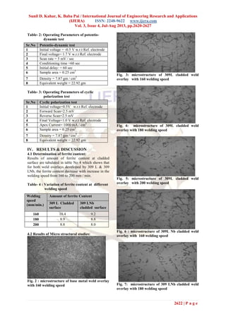
Fig. 1: Schematic Diagram of ESSC Process
The interior temperature of the bath is in vicinity of
19250
C. The surface temperature is approximately
16500
C. Melted electrode and the base metal collect
in pool beneath the molten slag bath and slowly
solidifies to form the clad [8]. Out of all welding
parameters, welding speed is significantly influence
the ferrite content & dilution of weld overlays. If a
very low welding speed is selected during cladding, it
will the result in very low dilution but at the same
time acquiring an unacceptable high content of ferrite
as it can be impairs the corrosion resistance and the
ductility of the welded overlay. In this present work,
electro slag strip cladding process were used to
developed weld overlay of 309L & 309L Nb
austenitic stainless steel on Cr-Mo steel with
variation of welding speeds of 160 to 200 mm/min. at
fixed current (1,200 Amps) and Voltage(24 Volts).
Weld overlay are under gone various corrosion
problem such as general, pitting and inter granular
corrosion under service conditions. So the corrosion
behavior of both weld overlay will be studied in
different corrosive environments using various
corrosion tests such as potentiodynamic study &
cyclic polarization study [9].
II. EXPERIMENTAL PROCEDURE
2.1 Development of weld overlays:
The base material of 55 mm thick plate of SA387
Gr11 Cl2 steel received in the normalized were
cladded with single layer of 309 L & 309L Nb by
electro-slag strip cladding process using the
following welding conditions.
Polarity: DECP
Current1100A-1300A
Voltage: 24-26 V
Travel speed: 160,180,200 mm/min
Electrode extension (Stick out): 35 mm max.
Height of flux: 20-25 mm
Preheat temperature: 1250
C min
Inter pass temperature: 2000
C max.
Chemical composition of base metal & strip
electrodes were measured with the help of X-ray
florescent scope and tabulated in table-1.
Table-1: chemical Composition of base metal and
strip electrodes (weight%)
2.2 Sample Preparation:
Slices of cladded plates have been done across the
width area and it was taper grinded on milling
machine at angle of 10-15 degree for necessary
testing.
III. TESTING & EVALUATION
3.1 Visual Examination:
This is done for bead shape observation &
checking any welding defect like undercut during the
welding process.
3.2 Determination of Ferrite Content:
Ferrite content was measured with the help
of Fischer Ferrite- scope MP 30 for all types weld
overlays samples.
3.3 Microstructure Evaluation:
Neophot – 2 Microscope is used to observer
micro structural changes at grain boundary as well as
at interface using following etchant.
Etchant for Base Metal: Nital (98% Methanol &
2% HNO3) solution.
Etchant for cladded region: Aquzregia (75% HCl
& 25% HNO3) solution.
All samples were viewed at 400X Magnification.
3.4 Corrosion Testing:
Potentiodynamic studies were carried out on
both weld overlays in 0.1 N H2SO4 solution & 0.1 N
HNO3 solution as per ASTM G-5 standard, while
cyclic polarization studies were carried out on both
weld overlays in 6 % FeCl3 Solution as per ASTM
G-61 standard using Potentiostat Gammry Reference
600. Corrosion cell was consist of Calomel electrode
as reference electrode, graphite rod as counter
electrode and test sample as working electrode.
Type Base Metal 309L
Clad
309L Nb
Clad
%C 0.15 0.005 0.005
% Cr 1.2 21.0 21.0
% Ni 0.16 11.0 11.0
% Mo 0.5 <0.03 <0.03
% Si 0.6 0.5 0.5
% Mn 1.2 1.8 1.8
% Nb 0.001 - 0.52
% N2 - 0.0036 0.0036
% P 0.003 0.012 0.012
% S <0.001 0.005 0.005](https://image.slidesharecdn.com/oz3426202627-130913054509-phpapp02/85/Oz3426202627-2-320.jpg)
![Sunil D. Kahar, K. Baba Pai / International Journal of Engineering Research and Applications
(IJERA) ISSN: 2248-9622 www.ijera.com
Vol. 3, Issue 4, Jul-Aug 2013, pp.2620-2627
2626 | P a g e
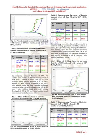
Table 12: electrochemical parameters of cyclic
scan of 309L weld overlay in 6% FeCl3 Solution
By comparing pitting behavior of 309L cladded weld
overlays at different Welding speed in 6% FeCl3
solution, it shows that Epit < Ecorr for all welding
speed which indicate that pitting will occur &
damage passive film will not repaired which leads to
further corrosion.
4.4.3 Effect of Welding Speed on Pitting
corrosion behaviours of 309LNb cladded weld
overlays in 6% FeCl3 Solution
Fig. 17 : cyclic polarization scans of 309 L Nb
cladded weld overlays at different welding speed
in 6% FeCl3 Solution
Table 13: electrochemical parameters of cyclic
scan of 309L Nb weld overlay in 6% FeCl3
Solution
By comparing corrosion behavior of 309L Nb
cladded weld overlays at different Welding speed in
6% FeCl3 solution it shows that Epit > Ecorr for 180
mm / min. welding speed which indicate that the
pitting will occur but damage passive film will
repaired & protecting further corrosion while in case
of 160 & 200 mm / min. welding speed Epit < Ecorr
which indicate that pitting will occur & damage
passive film will not repaired which leads to further
corrosion.
V. CONCLUSIONS
1. Electroslag strip cladding process can be
advantageously and profitably used to deposit
austenitic stainless steel weld overlays on low-
alloy steel.
2. Amount of ferrite content is decrease with
increase the welding speed from 160 to 200 mm
/min for both weld overlays developed by 309 L
& 309 L Nb grade austenitic stainless steel.
3. Corrosion rate is decrease with increase the
welding speed from 160 to 200 mm /min for
both weld overlays developed by 309 L and 309
L Nb grade austenitic stainless steel in 0.1 N
H2SO4 and 0.1N HNO3 solutions.
4. Both weld overlays developed by 309 L and 309
LNb grade austenitic stainless steel exhibit best
corrosion resistance at 200 mm /min welding
speed in 0.1N HNO3 solution.
5. Both weld overlays developed by 309 L and 309
LNb grade austenitic stainless steel exhibit best
corrosion resistance at 180 mm /min. welding
speed in 0.1 N H2SO4 solution.
6. 309L cladded weld overlay developed at all
welding speed has lower pitting resistance in 6%
FeCl3 solution.
7. 309L Nb cladded weld overlay developed with
180 mm /min. welding speed has good pitting
resistance than weld overlay developed with 160
& 200 mm /min. in 6% FeCl3 solution.
REFERENCES
Journal Papers:
[1] Susan Pak, Solveig Rigdal, Leif Karlsson, Ann-
Charlotte Gustavsson, Electroslag and
submerged arc stainless steel cladding, Anti-
Corrosion Methods and Materials, Vol. 45 ( 1),
42 - 45 .
[2] R. paschold, l. karlsson, M. F. Gittos, Karlsson.
L, Pak. S. and Gustavsson, Disbonding of
Austenitic Weld Overlays in Hydro-processing
Applications, SVETSAREN, The ESAB welding
and cutting journal vol. 62 (1), 2007, 17-19.
[3] Soudokay Strip Cladding, Bohler Thyssen
Welding BELGIUM, online article,
www.soudkay.be
[4] Professor J.H. Devletian, Member, Y.P. Gao,
Q.H. Zhao, Visitors, and Professor W. E. Wood,
Strip Cladding of Main Propeller Shafting with
Ni Alloy 625 by Electroslag Surfacing,12.
[5] I. G. Rodionova, A. A. Sharapov, V. I. Puzachev,
V. A. Grishin, V. L. Mirochnik, and A. N.
Parameters 309 L Cladded weld overlay
Welding speed
(mm/min.)
160 180 200
C.R.(mpy) 463.0 203.2 395.5
Epit (mV) -195.3 -350.4 -136.2
Ecorr(mV) -13.00 -291.00 -70.80
Icorr( µA) 309.0 135.0 264.0
Parameters 309 LNb Cladded weld
overlay
Welding speed
(mm/min.)
160 180 200
C.R.(mpy) 275.9 70.62 155.0
Epit (mV) -478.6 -192.8 -167.3
Ecorr(mV) -388.0 -222.0 -153.0
Icorr( µA) 184.0 47.10 103.0](https://image.slidesharecdn.com/oz3426202627-130913054509-phpapp02/85/Oz3426202627-7-320.jpg)
![Sunil D. Kahar, K. Baba Pai / International Journal of Engineering Research and Applications
(IJERA) ISSN: 2248-9622 www.ijera.com
Vol. 3, Issue 4, Jul-Aug 2013, pp.2620-2627
2627 | P a g e
Rybkin, Technology use of electroslag
hardfacing to improve the quality of corrosion –
resistance bimetal, Chemical and Petroleum
Engineering. Vol. 34 (1-2), 1998, 22
[6] Dipl.-Ing. R. Paschold, ESAB GmbH, Solingen,
Germany, Electroslag strip cladding for
corrosion resistance, A welding review published
by ESAB AB, Sweden Vol.2-3, 2001, 62.
[7] Tapobrata Datta, Electroslag Strip Cladding-
Principle, Process Control and Application, 43
[8] K. Darowicki, S. Krakowiak, Electrochemical
investigations of stainless steels used in flue-
gasdesulphurization units, Anti-Corrosion
Methods and Materials, Vol. 44 (6), (1997),376.
[9] Dipl.-Ing. R. Paschold, ESAB GmbH, Solingen,
Germany “Electroslag strip cladding for
corrosion resistance”, A welding review
published by ESAB AB, Sweden No. 2-3, 2001,
66.](https://image.slidesharecdn.com/oz3426202627-130913054509-phpapp02/85/Oz3426202627-8-320.jpg)

This study investigates the corrosion behavior of electro-slag strip cladded weld overlays using 309L and 309LNB stainless steel on CR-Mo steel across different welding speeds. Results indicate that increased welding speed reduces ferrite content and enhances corrosion resistance in acidic environments, with optimal performance at 180 mm/min. The electrochemical analysis shows that weld overlays demonstrate passive behavior in both sulfuric and nitric acid solutions, particularly showing superior corrosion resistance at higher welding speeds.


