Download to read offline


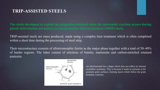


TRIP-assisted steels are mass produced steels that use a complex heat treatment to develop a microstructure consisting of allotriomorphic ferrite, bainite, martensite, and retained austenite. Their major application is in the automobile industry. There are two types of TRIP-assisted steels that differ in their heat treatment process. TWIP steels are austenitic and accommodate strain through dislocation glide and mechanical twinning, resulting in high ductility and strength. Micro-alloyed steels produced by controlled rolling have moderate strength, good toughness and weldability, and are widely used in applications like pipelines. The embrittlement and fracture of steels depends on