SITP / O& G Ono SLIDE 1
OIL AND GAS SEPARATION PROCESS
SEPARATION
Process Whereby Reservoir
Fluid is separated Into its
Component Phases of Gas
Liquid and Solid
The Liquid Phase is Further
Separated into Water and Oil
Objectives of Separation
Removal of Contaminants
Maximizing Oil Production
Meeting Transport/Customer
Specification
Metering for Royalty/Tax
Payment
Non-Solution Gas Required
Removed Before Metering
Reservoir Fluid
Complex, High temperature,
High Pressure, High Velocity,
Quite Turbulent, and Constantly
Expanding Mixture of
Hydrocarbon Liquid
Water Vapour
Free Water
Solids
Other Undesirable
Compounds Considered
Contaminants.
2.
SITP / O& G Ono SLIDE 2
Reservoir Fluid
During Flowing Process
It Undergoes Continuous
Temperature and Pressure
Reduction
Gases Evolve
Water Vapour Condenses
Some Hydrocarbon Change their
Characteristics Resulting in
Foaming
Bubbles
Mist
Hydrates
Free Gas
Reservoir Fluid Processing
Processing of Separated Products to
Sellable, Reusable or Disposable
Quality
Gas
Removal of Contaminants
Removal of Water Vapour
Removal of Condensate and
Hydrocarbon Vapour
Crude Oil
Removal of Water
Removal of Contaminants
Water
Removal of Oil
Removal of Contaminants
3.
SITP / O& G Ono SLIDE 3
SEPARATORS
Pressure Vessels Used to
Separate Reservoir Fluids Into
Gas, Liquid and Sediments.
Types of Separators
Free-Liquid Removing Vessel
Removes Free-Water From
Well Fluids
Removes Free-Liquid From
Gas Stream
Removal is Preferably Before
Pressure Reduction
Removal Reduces Process Load
Removal Prevents:
Corrosion
Hydrates Formation
Tight Emulsion
Formation
Types of Free-Liquid Knock-out
Trap
Knock-out Trap
Knock-out Vessel
Knock-out Drum
Free-Water Knock-out
Liquid Knock-out
Producing Field Vessels
Used in Processing Lease or
Platform Reservoir Fluids
Types Include
Oil & Gas Separators
Stage Separators
SITP / O& G Ono SLIDE 5
SEPARATORS
Components of Separator
.....................
6.
SITP / O& G Ono SLIDE 6
Separator Components/Functions
Types of Inlet Diverter Devices
Mechanical Agitation Inlet
Devices
Mechanism
Well Stream Strikes Device
Reduction in Velocity
Change in Direction of Flow.
Types of Mechanical Agitation
Inlet Devices
Deflector Baffles
Hemispherical Disc
Flat Plate
Piece of Angle Iron
Metal Cone.
Primary Separation Section
Removes Bulk of Liquid Slugs
and Particles
Removal Achieved Through
Momentum Reduction
Reduction Achieved by Stream
Inlet Baffling(Regulating) or/and
Inlet Diverter Devices
Inlet Diverter Devices
Cause Rapid Change in Inlet
Stream Velocity
Results Liquid and Gas
Disengagement.
7.
SITP / O& G Ono SLIDE 7
Inlet Diverters
.
Flow Against Plate Flow Through Baffle
Gas Entry With Deflector Inlet Diffuser
Cyclone Inlet Diverter
8.
SITP / O& G Ono SLIDE 8
Secondary Separation Section .
Reduces Fluid Velocity From the
Primary Section.
Minimises the Turbulence.
Creates Room for Gravity Settling.
Thus Removes Gas Vapour From Oil.
It Removes Water (in the 3– Phase
Separator).
Should Be Large and of Sufficient
Height or Length.
There Should Be Proper Positioning of
Straightening Vanes for Uniform Flow.
Orienting Plates/baffles
Reduces Turbulence
Separator Diverters and Sections
Cyclone Inlet.
Mechanism
Creates a High Fluid Velocity
Fluid Get Spun Around the Wall
on Entry
Spinning Subjects Fluid to High
Centrifugal Forces up to 500
Times the Force of Gravity
Forward Motion of Heavy Liquid
is Stopped and It Falls to Flow
Along That Wall to Bottom.
9.
SITP / O& G Ono SLIDE 9
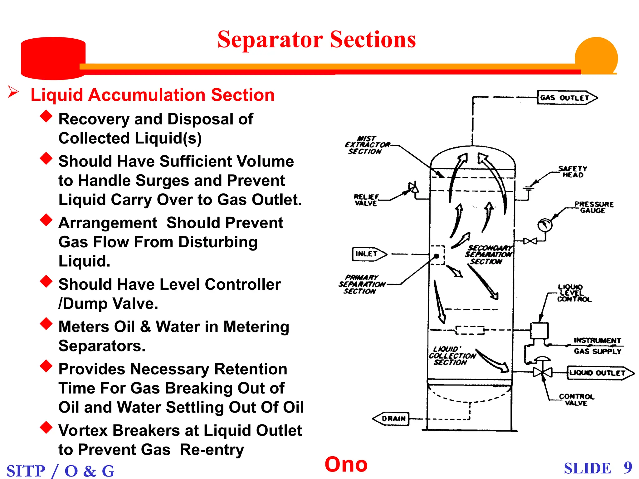
Separator Sections
Liquid Accumulation Section
Recovery and Disposal of
Collected Liquid(s)
Should Have Sufficient Volume
to Handle Surges and Prevent
Liquid Carry Over to Gas Outlet.
Arrangement Should Prevent
Gas Flow From Disturbing
Liquid.
Should Have Level Controller
/Dump Valve.
Meters Oil & Water in Metering
Separators.
Provides Necessary Retention
Time For Gas Breaking Out of
Oil and Water Settling Out Of Oil
Vortex Breakers at Liquid Outlet
to Prevent Gas Re-entry
10.
SITP / O& G Ono SLIDE 10
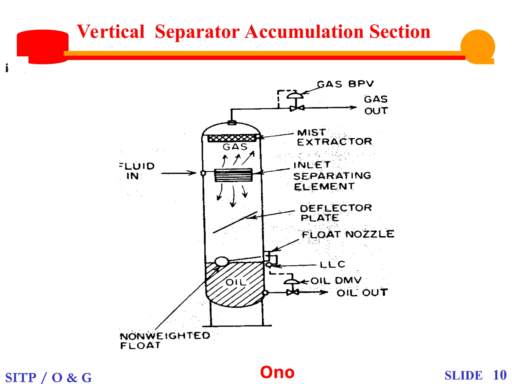
Vertical Separator Accumulation Section
.
i
11.
SITP / O& G Ono SLIDE 11
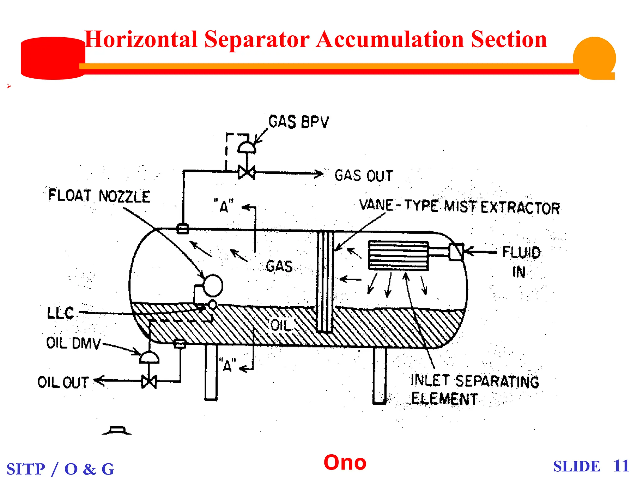
Horizontal Separator Accumulation Section
.
12.
SITP / O& G Ono SLIDE 12
Spherical Separator Accumulation Section
.
13.
SITP / O& G Ono SLIDE 13
Accumulation Section Accessories.
Wave Breakers(Arresters).
Perpendicular Vertical Baffles
in the Gas-liquid Interface
Which Prevents Waves
Caused by Liquid Surge.
Defoaming Plates
Inclined Parallel Plates or
Tubes in the Gas-Liquid
Interface Which Break Foams.
Foam is Forced Through
Them and Gets Coalesced to
Form Liquid.
14.
SITP / O& G Ono SLIDE 14
Accumulation Section Accessories.
Vortex Breakers.
Metal Plate Devices Which
Prevent Vortex Formation
When Control Valve is Open.
Vortices Develop When the
Control Valve is Open
Resulting in Gas Being Sucked
Out of the Vapour Space and
Getting Re-entrained Into
Liquid
15.
SITP / O& G Ono SLIDE 15
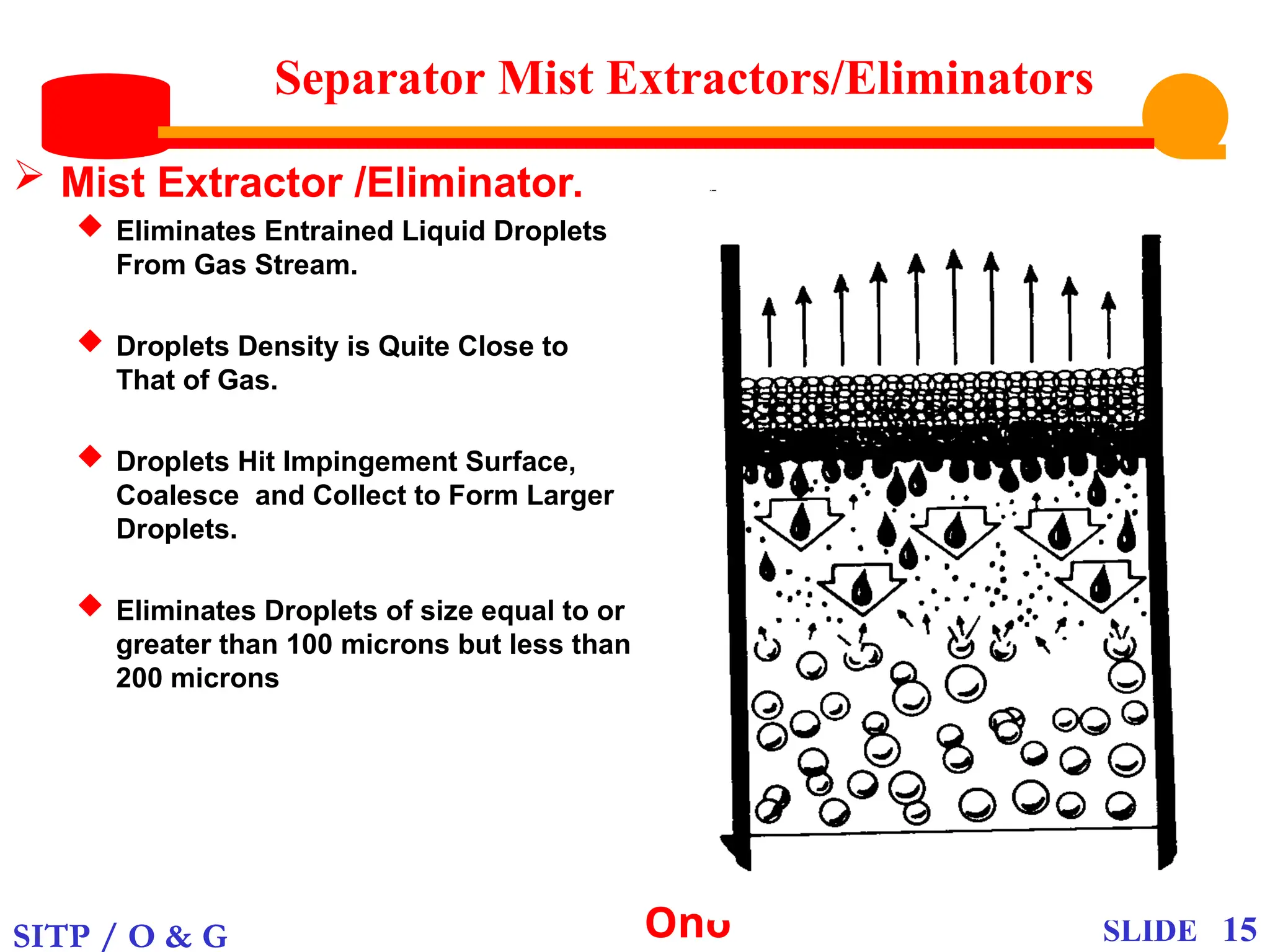
Separator Mist Extractors/Eliminators
Mist Extractor /Eliminator.
Eliminates Entrained Liquid Droplets
From Gas Stream.
Droplets Density is Quite Close to
That of Gas.
Droplets Hit Impingement Surface,
Coalesce and Collect to Form Larger
Droplets.
Eliminates Droplets of size equal to or
greater than 100 microns but less than
200 microns
16.
SITP / O& G Ono SLIDE 16
Types of Mist Extractors/Eliminators
Vane – Type Mist Extractor.
Consisting of Labyrinth of Metal Plates
Laid Parallel With Liquid Collection
Pockets Leading to Drain Pipe
Mechanism of Separation
Impingement With High Centrifugal
Force.
Obstruction to Entrained Liquid
Particles.
Change in Direction of Flow.
Gas Stream Veers Around
Obstruction While Liquid Drops.
Droplets Collide With the Walls and
Get Separated From the Gas.
Wire-Mesh Mist Extractor
Employs Impingement Mechanism
Primarily to Remove Liquid Droplets.
Entrained Liquid Particles Strike the Metal
Surface Then Flow Down the Capillary
Space Provided by Wires.
Surfaces Tension Holds the Liquid at the
Lower Face of the Pad Until Such a Time
That the Droplets Weight Let Go Under
Gravity.
Liquid Collects in the Spaces and
Continue Downward.
Stainless Steel Woven-wire Mesh Has
Highest Gas and Liquid Separation
Capacity.
Liquid Carry-over 0.1 gal/mscf
Efficiency 90%.
SITP / O& G Ono SLIDE 18
Separator External Components
Control Devices
Level Control.
Done by Level Controller in
Either the Gas/oil or
Oil /Water Interface.
Generally Float-operated
Pilots
Prevents Damages Caused
by Separator Low or High
Level
Normally Activates
Dump Valve on Sensing
High Liquid Level.
Block Valve on Inlet
Bypass Valve
An Alarm
19.
SITP / O& G Ono SLIDE 19
Separator External Components
Pressure Control
Done in the Vapour Space With a
Pressure Controller and Back
Pressure Control Valve.
Control Valve is Located on Gas
Exit Line.
Controller Senses Abnormality
and Regulates the Control Valve
to Release Gas.
Controls Can be Mechanical,
Pneumatic or Electric
Normally Activates
A Shut-in Valve
A Bypass Valve
An Alarm
Temperature Controls
Mostly on Special cases
Separators
Functions to
Shut-in the Separator
Open or Close a Bypass to
Heater
Activates an Alarm
20.
SITP / O& G Ono SLIDE 20
Separator Operating Pressures
Maximum Allowable Working
Pressure (MAWP)
Maximum Pressure on Top of
the Separator at Its Normal
Operating Condition for That
Designated Temperature.
Pressure Beyond Which
Vessel or Pipe Should NOT
be Operated
It Is Normally Stipulated by
the ASME.
Determined by Vessel
Material, Thickness and
Temperature
Set Pressure
Pressure at Which Safety
Device Gets Activated
Normally Equals or Greater
than MAWP
Operating Pressure (OP)
Pressure in the Vessel
During Normal Operation
OP 90% MAWP
Pressure Relief
Device Pressure.
21.
SITP / O& G Ono SLIDE 21
Separator External Components
Safety Devices
Prevent Accidents and Damage
such as Vessel Rupture
Generally Prevent
Over- or Under-pressure
Low or High Liquid Levels
Low or High Temperature
Relief Valve
Spring-Loaded Valve that
Raises Slowly with Pressure
Increase
Used Mainly for Liquid
Pressure Control
Safety Valve
Spring-Loaded Valve that
Pops Open with Pressure
Increase.
Mostly Applicable with Gas
or Vapour Pressure
Controls.
Safety Relief Valve.
Spring-Loaded Valve
Designed to Work as Both
Safety and Relief Valves.
Sized and Designed to Open
Before or at MAWP
Pressure > Separator
Maximum Operating
Pressure.