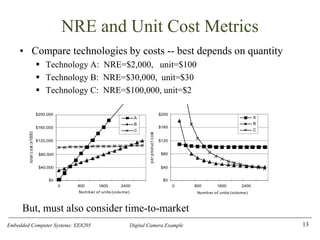
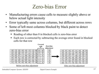
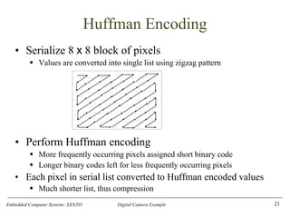
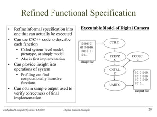
The document describes the design of a simple digital camera. It discusses the key requirements of capturing images, storing them digitally, and downloading images to a computer. It outlines the main components that would be needed, including a charge-coupled device (CCD) sensor to capture light as digital values, memory to store images, and an interface to transfer images to a computer. The document also discusses some of the main design challenges, such as optimizing various metrics like cost, power usage, performance and time to market.
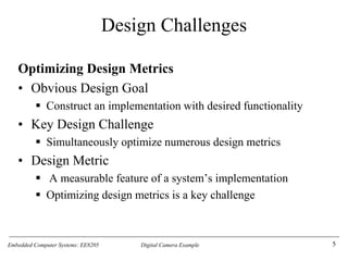
![Embedded Computer Systems: EE8205 Digital Camera Example
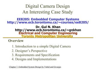
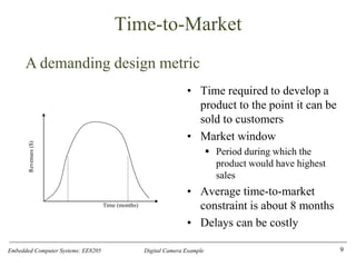
CCD Module
Simulates a Real CCD
▪ CcdInitialize is passed name of image file
▪ CcdCapture reads “image” from file
▪ CcdPopPixel outputs pixels one at a time
30
char CcdPopPixel(void) {
char pixel;
pixel =
buffer[rowIndex][colIndex];
if( ++colIndex == SZ_COL ) {
colIndex = 0;
if( ++rowIndex == SZ_ROW ) {
colIndex = -1;
rowIndex = -1;
}
}
return pixel;
}
#include <stdio.h>
#define SZ_ROW 64
#define SZ_COL (64 + 2)
static FILE *imageFileHandle;
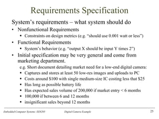
static char
buffer[SZ_ROW][SZ_COL];
static unsigned rowIndex,
colIndex;
void CcdInitialize(const char *imageFileName) {
imageFileHandle = fopen(imageFileName, "r");
rowIndex = -1;
colIndex = -1;
}
void CcdCapture(void) {
int pixel;
rewind(imageFileHandle);
for(rowIndex=0; rowIndex<SZ_ROW; rowIndex++) {
for(colIndex=0; colIndex<SZ_COL; colIndex++) {
if( fscanf(imageFileHandle, "%i", &pixel)
== 1 ) {
buffer[rowIndex][colIndex] = (char)pixel;
}
}
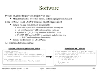
}
rowIndex = 0;
colIndex = 0;
}](https://image.slidesharecdn.com/digital-camera-casestudy-240312061951-71eb5da9/85/digital-camera-image-capturing-technique-30-320.jpg)
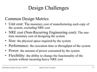
![Embedded Computer Systems: EE8205 Digital Camera Example
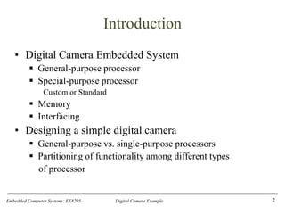
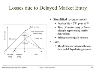
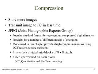
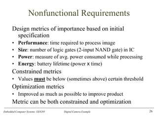
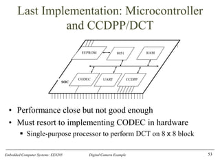
CCDPP (CCD PreProcessing) Module
Performs zero-bias Adjustment
• CcdppCapture uses CcdCapture and
CcdPopPixel to obtain the image
• Performs zero-bias adjustment after each
row read in
31
#define SZ_ROW 64
#define SZ_COL 64
static char
buffer[SZ_ROW][SZ_COL];
static unsigned rowIndex,
colIndex;
void CcdppInitialize() {
rowIndex = -1;
colIndex = -1;
}
void CcdppCapture(void) {
char bias;
CcdCapture();
for(rowIndex=0; rowIndex<SZ_ROW; rowIndex++) {
for(colIndex=0; colIndex<SZ_COL; colIndex++) {
buffer[rowIndex][colIndex] = CcdPopPixel();
}
bias = (CcdPopPixel() + CcdPopPixel()) / 2;
for(colIndex=0; colIndex<SZ_COL; colIndex++) {
buffer[rowIndex][colIndex] -= bias;
}
}
rowIndex = 0;
colIndex = 0;
}
char CcdppPopPixel(void) {
char pixel;
pixel =
buffer[rowIndex][colIndex];
if( ++colIndex == SZ_COL ) {
colIndex = 0;
if( ++rowIndex == SZ_ROW )
{
colIndex = -1;
rowIndex = -1;
}
}
return pixel;
}](https://image.slidesharecdn.com/digital-camera-casestudy-240312061951-71eb5da9/85/digital-camera-image-capturing-technique-31-320.jpg)
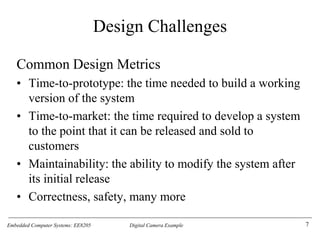
![Embedded Computer Systems: EE8205 Digital Camera Example
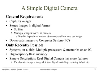
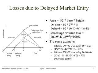
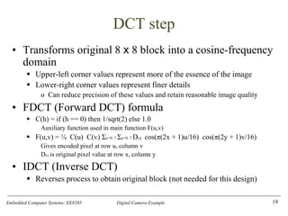
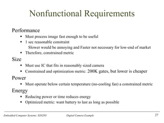
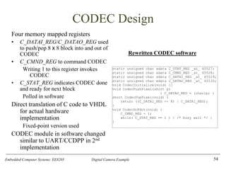
CODEC Module
• Models FDCT encoding
• ibuffer holds original 8 x 8 block
• obuffer holds encoded 8 x 8 block
• CodecPushPixel called 64 times to fill
ibuffer with original block
• CodecDoFdct called once to
transform 8 x 8 block
▪ Explained in next slide
• CodecPopPixel called 64 times to
retrieve encoded block from obuffer
33
static short ibuffer[8][8],
obuffer[8][8], idx;
void CodecInitialize(void) { idx = 0;
}
void CodecDoFdct(void) {
int x, y;
for(x=0; x<8; x++) {
for(y=0; y<8; y++)
obuffer[x][y] = FDCT(x, y,
ibuffer);
}
idx = 0;
}
void CodecPushPixel(short p) {
if( idx == 64 ) idx = 0;
ibuffer[idx / 8][idx % 8] = p;
idx++;
}
short CodecPopPixel(void) {
short p;
if( idx == 64 ) idx = 0;
p = obuffer[idx / 8][idx % 8];
idx++;
return p;
}](https://image.slidesharecdn.com/digital-camera-casestudy-240312061951-71eb5da9/85/digital-camera-image-capturing-technique-33-320.jpg)
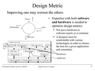
![Embedded Computer Systems: EE8205 Digital Camera Example
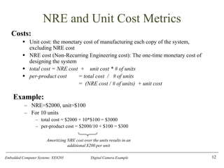
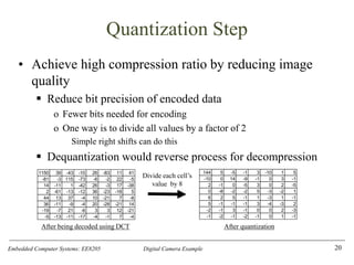
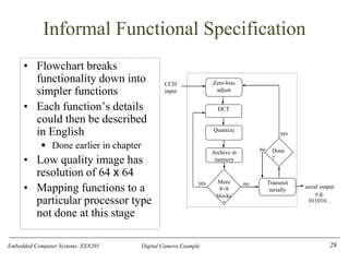
CODEC
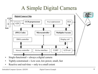
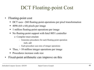
Implementing FDCT Formula
C(h) = if (h == 0) then 1/sqrt(2) else 1.0
F(u,v) = ¼ C(u) C(v) Σx=0..7 Σy=0..7 Dxy cos(π(2x + 1)u/16) cos(π(2y + 1)v/16)
Only 64 possible inputs to COS, so table can be used to save performance time
▪ Floating-point values multiplied by 32,678 and rounded to nearest integer
▪ 32,678 chosen in order to store each value in 2 bytes of memory
▪ Fixed-point representation explained more later
FDCT unrolls inner loop of summation, implements outer summation as two consecutive for loops
34
static short ONE_OVER_SQRT_TWO = 23170;
static double COS(int xy, int uv) {
return COS_TABLE[xy][uv] / 32768.0;
}
static double C(int h) {
return h ? 1.0 : ONE_OVER_SQRT_TWO /
32768.0;
}
static const short COS_TABLE[8][8] = {
{ 32768, 32138, 30273, 27245, 23170, 18204, 12539, 6392 },
{ 32768, 27245, 12539, -6392, -23170, -32138, -30273, -18204 },
{ 32768, 18204, -12539, -32138, -23170, 6392, 30273, 27245 },
{ 32768, 6392, -30273, -18204, 23170, 27245, -12539, -32138 },
{ 32768, -6392, -30273, 18204, 23170, -27245, -12539, 32138 },
{ 32768, -18204, -12539, 32138, -23170, -6392, 30273, -27245 },
{ 32768, -27245, 12539, 6392, -23170, 32138, -30273, 18204 },
{ 32768, -32138, 30273, -27245, 23170, -18204, 12539, -6392 }
};
static int FDCT(int u, int v, short img[8][8]) {
double s[8], r = 0; int x;
for(x=0; x<8; x++) {
s[x] = img[x][0] * COS(0, v) + img[x][1] * COS(1, v)
+ img[x][2] * COS(2, v) + img[x][3] * COS(3, v)
+ img[x][4] * COS(4, v) + img[x][5] * COS(5, v)
+ img[x][6] * COS(6, v) + img[x][7] * COS(7, v);
}
for(x=0; x<8; x++) r += s[x] * COS(x, u);
return (short)(r * .25 * C(u) * C(v));
}](https://image.slidesharecdn.com/digital-camera-casestudy-240312061951-71eb5da9/85/digital-camera-image-capturing-technique-34-320.jpg)
![Embedded Computer Systems: EE8205 Digital Camera Example
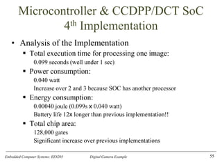
CNTRL (controller) Module
Heart of the system
CntrlInitialize for consistency with other modules only
CntrlCaptureImage uses CCDPP module to input image and place in buffer
CntrlCompressImage breaks the 64 x 64 buffer into 8 x 8 blocks and performs FDCT on each
block using the CODEC module. Also performs quantization on each block
CntrlSendImage transmits encoded image serially using UART module
35
void CntrlSendImage(void) {
for(i=0; i<SZ_ROW; i++)
for(j=0; j<SZ_COL; j++) {
temp = buffer[i][j];
UartSend(((char*)&temp)[0]); // send upper byte
UartSend(((char*)&temp)[1]); // send lower byte
}
}
}
#define SZ_ROW 64
#define SZ_COL 64
#define NUM_ROW_BLOCKS (SZ_ROW / 8)
#define NUM_COL_BLOCKS (SZ_COL / 8)
static short buffer[SZ_ROW][SZ_COL];
static short i, j, k, l, temp;
void CntrlInitialize(void) {}
void CntrlCaptureImage(void) {
CcdppCapture();
for(i=0; i<SZ_ROW; i++)
for(j=0; j<SZ_COL; j++)
buffer[i][j] =
CcdppPopPixel();
}
void CntrlCompressImage(void) {
for(i=0; i<NUM_ROW_BLOCKS; i++)
for(j=0; j<NUM_COL_BLOCKS; j++) {
for(k=0; k<8; k++)
for(l=0; l<8; l++)
CodecPushPixel((char)buffer[i * 8 + k][j * 8 + l]);
CodecDoFdct();/* part 1 - FDCT */
for(k=0; k<8; k++)
for(l=0; l<8; l++) {
buffer[i * 8 + k][j * 8 + l] = CodecPopPixel();
/* part 2 - quantization */
buffer[i*8+k][j*8+l] >>= 6;
}
}
}](https://image.slidesharecdn.com/digital-camera-casestudy-240312061951-71eb5da9/85/digital-camera-image-capturing-technique-35-320.jpg)
![Embedded Computer Systems: EE8205 Digital Camera Example
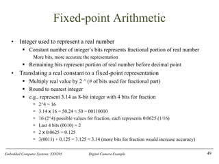
Overall System
• Main initializes all modules, then uses CNTRL module to
capture, compress, and transmit one image
• This system-level model can be used for extensive
experimentation
▪ Bugs much easier to correct here rather than in later models
36
int main(int argc, char *argv[]) {
char *uartOutputFileName = argc > 1 ? argv[1] : "uart_out.txt";
char *imageFileName = argc > 2 ? argv[2] : "image.txt";
/* initialize the modules */
UartInitialize(uartOutputFileName);
CcdInitialize(imageFileName);
CcdppInitialize();
CodecInitialize();
CntrlInitialize();
/* simulate functionality */
CntrlCaptureImage();
CntrlCompressImage();
CntrlSendImage();
}](https://image.slidesharecdn.com/digital-camera-casestudy-240312061951-71eb5da9/85/digital-camera-image-capturing-technique-36-320.jpg)
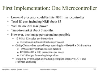
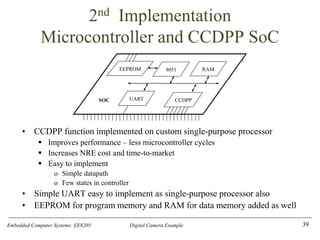
![Embedded Computer Systems: EE8205 Digital Camera Example
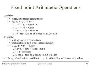
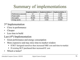
CCDPP
• Hardware implementation of zero-bias
operations
• Interacts with external CCD chip
▪ CCD chip resides external to our SOC as
combining CCD with ordinary logic not feasible
• Internal buffer, B, mem-mapped to 8051
• Variables R, C are row, column indices
• GetRow reads in one row from CCD to B
▪ 66 bytes: 64 pixels + 2 blacked-out pixels
• ComputeBias state computes bias for that
row and stores in variable Bias
• FixBias state iterates over same row
subtracting Bias from each element
• NextRow transitions to GetRow for repeat
of process on next row or to Idle state when
all 64 rows completed
42
C = 64
C < 64
R = 64 C =
66
invoked
R < 64
C < 66
Idle:
R=0
C=0
GetRow:
B[R][C]=Pxl
C=C+1
ComputeBias:
Bias=(B[R][11]
+ B[R][10]) / 2
C=0
NextRow:
R++
C=0
FixBias:
B[R][C]=B[R][C]-
Bias
FSMD description of CCDPP](https://image.slidesharecdn.com/digital-camera-casestudy-240312061951-71eb5da9/85/digital-camera-image-capturing-technique-42-320.jpg)
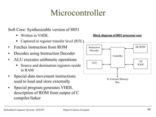
![Embedded Computer Systems: EE8205 Digital Camera Example
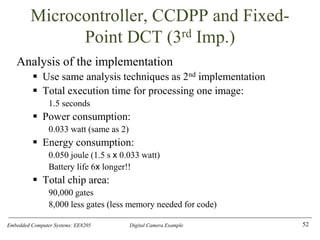
Fixed-point Implementation of CODEC
• COS_TABLE gives 8-bit fixed-
point representation of cosine
values
• 6 bits used for fractional portion
• Result of multiplications shifted
right by 6
51
void CodecDoFdct(void) {
unsigned short x, y;
for(x=0; x<8; x++)
for(y=0; y<8; y++)
outBuffer[x][y]= F(x,y, inBuffer);
idx = 0;
}
static const char code COS_TABLE[8][8] = {
{ 64, 62, 59, 53, 45, 35, 24, 12 },
{ 64, 53, 24, -12, -45, -62, -59, -35 },
{ 64, 35, -24, -62, -45, 12, 59, 53 },
{ 64, 12, -59, -35, 45, 53, -24, -62 },
{ 64, -12, -59, 35, 45, -53, -24, 62 },
{ 64, -35, -24, 62, -45, -12, 59, -53 },
{ 64, -53, 24, 12, -45, 62, -59, 35 },
{ 64, -62, 59, -53, 45, -35, 24, -12 }
};
static const char ONE_OVER_SQRT_TWO = 5;
static short xdata inBuffer[8][8];
static short outBuffer[8][8], idx;
void CodecInitialize(void) { idx = 0; }
static unsigned char C(int h)
{ return h ? 64 : ONE_OVER_SQRT_TWO;}
static int F(int u, int v, short img[8][8]) {
long s[8], r = 0;
unsigned char x, j;
for(x=0; x<8; x++) {
s[x] = 0;
for(j=0; j<8; j++)
s[x] += (img[x][j] * COS_TABLE[j][v] ) >> 6;
}
for(x=0; x<8; x++) r += (s[x] * COS_TABLE[x][u])>> 6;
return (short)((((r * (((16*C(u)) >> 6) *C(v)) >> 6))
>> 6) >> 6);
}
void CodecPushPixel(short p) {
if( idx == 64 ) idx = 0;
inBuffer[idx / 8][idx % 8] =
p << 6; idx++;
}](https://image.slidesharecdn.com/digital-camera-casestudy-240312061951-71eb5da9/85/digital-camera-image-capturing-technique-51-320.jpg)


![casestudyofdigitalcamera-140715113252-phpapp01[1].pptx](https://cdn.slidesharecdn.com/ss_thumbnails/casestudyofdigitalcamera-140715113252-phpapp011-240904060527-344825f6-thumbnail.jpg?width=640&height=640&fit=bounds)


