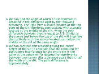
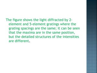
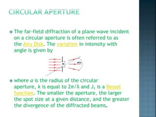
G. Karthik
BSC(MPCs)-2a
121418468012
INTRODUCTION
Single-slit diffraction
Circular aperture
Polarisation
Diffraction refers to various
phenomena that occur when
a wave encounters an obstacle or a
slit. It is defined as the bending of
waves around the corners of an
obstacle or through an aperture into
the region of geometrical shadow of
the obstacle/aperture. The diffracting
object or aperture effectively becomes
a secondary source of the propagating
wave.
 A long slit of infinitesimal width which is
illuminated by light diffracts the light into a
series of circular waves and the wavefront which
emerges from the slit is a cylindrical wave of
uniform intensity, in accordance with Huygens–
Fresnel principle.
 A slit which is wider than a wavelength produces
interference effects in the space downstream of
the slit. These can be explained by assuming
that the slit behaves as though it has a large
number of point sources spaced evenly across
the width of the slit. The analysis of this system
is simplified if we consider light of a single
wavelength. If the incident light is coherent,
these sources all have the same phase.
 We can find the angle at which a first minimum is
obtained in the diffracted light by the following
reasoning. The light from a source located at the top
edge of the slit interferes destructively with a source
located at the middle of the slit, when the path
difference between them is equal to λ/2. Similarly,
the source just below the top of the slit will interfere
destructively with the source located just below the
middle of the slit at the same angle.
 We can continue this reasoning along the entire
height of the slit to conclude that the condition for
destructive interference for the entire slit is the
same as the condition for destructive interference
between two narrow slits a distance apart that is half
the width of the slit. The path difference is
approximately .
 Light incident at a given point in the space
downstream of the slit is made up of
contributions from each of these point
sources and if the relative phases of these
contributions vary by 2π or more, we may
expect to find minima and maxima in the
diffracted light. Such phase differences are
caused by differences in the path lengths
over which contributing rays reach the point
from the slit.
The figure shows the light diffracted by 2-
element and 5-element gratings where the
grating spacings are the same; it can be seen
that the maxima are in the same position,
but the detailed structures of the intensities
are different.
 The far-field diffraction of a plane wave incident
on a circular aperture is often referred to as
the Airy Disk. The variation in intensity with
angle is given by
 where a is the radius of the circular
aperture, k is equal to 2π/λ and J1 is a Bessel
function. The smaller the aperture, the larger
the spot size at a given distance, and the greater
the divergence of the diffracted beams.
 Polarization (also polarisation) is a property
applying to transverse waves that specifies
the geometrical orientation of
the oscillations . In a transverse wave, the
direction of the oscillation is perpendicular
to the direction of motion of the wave.
 Most sources of light are classified as
incoherent and unpolarized (or only "partially
polarized") because they consist of a random
mixture of waves having different spatial
characteristics, frequencies (wavelengths),
phases, and polarization states.
 Characterizing an optical system in relation
to a plane wave with those given parameters
can then be used to predict its response to a
more general case, since a wave with any
specified spatial structure can be
decomposed into a combination of plane
waves (its so-called angular spectrum).
 Electromagnetic waves (such as light),
traveling in free space or
another homogeneous isotropic non-
attenuating medium, are properly described
as transverse waves, meaning that a plane
wave's electric field vector E and magnetic
field H are in directions perpendicular to (or
"transverse" to) the direction of wave
propagation; E and H are also perpendicular
to each other. By convention, the
"polarization" direction of an
electromagnetic wave is given by its electric
field vector.
 In addition to transverse waves, there are
many wave motions where the oscillation is
not limited to directions perpendicular to the
direction of propagation. These cases are far
beyond the scope of the current article
which concentrates on transverse waves
(such as most electromagnetic waves in bulk
media), however one should be aware of
cases where the polarization of a coherent
wave cannot be described simply using a
Jones vector, as we have just done.
THE END …..

diffraction , polarisation

  • 1.
  • 2.
  • 3.
    Diffraction refers tovarious phenomena that occur when a wave encounters an obstacle or a slit. It is defined as the bending of waves around the corners of an obstacle or through an aperture into the region of geometrical shadow of the obstacle/aperture. The diffracting object or aperture effectively becomes a secondary source of the propagating wave.
  • 4.
     A longslit of infinitesimal width which is illuminated by light diffracts the light into a series of circular waves and the wavefront which emerges from the slit is a cylindrical wave of uniform intensity, in accordance with Huygens– Fresnel principle.  A slit which is wider than a wavelength produces interference effects in the space downstream of the slit. These can be explained by assuming that the slit behaves as though it has a large number of point sources spaced evenly across the width of the slit. The analysis of this system is simplified if we consider light of a single wavelength. If the incident light is coherent, these sources all have the same phase.
  • 5.
     We canfind the angle at which a first minimum is obtained in the diffracted light by the following reasoning. The light from a source located at the top edge of the slit interferes destructively with a source located at the middle of the slit, when the path difference between them is equal to λ/2. Similarly, the source just below the top of the slit will interfere destructively with the source located just below the middle of the slit at the same angle.  We can continue this reasoning along the entire height of the slit to conclude that the condition for destructive interference for the entire slit is the same as the condition for destructive interference between two narrow slits a distance apart that is half the width of the slit. The path difference is approximately .
  • 6.
     Light incidentat a given point in the space downstream of the slit is made up of contributions from each of these point sources and if the relative phases of these contributions vary by 2π or more, we may expect to find minima and maxima in the diffracted light. Such phase differences are caused by differences in the path lengths over which contributing rays reach the point from the slit.
  • 7.
    The figure showsthe light diffracted by 2- element and 5-element gratings where the grating spacings are the same; it can be seen that the maxima are in the same position, but the detailed structures of the intensities are different.
  • 8.
     The far-fielddiffraction of a plane wave incident on a circular aperture is often referred to as the Airy Disk. The variation in intensity with angle is given by  where a is the radius of the circular aperture, k is equal to 2π/λ and J1 is a Bessel function. The smaller the aperture, the larger the spot size at a given distance, and the greater the divergence of the diffracted beams.
  • 9.
     Polarization (alsopolarisation) is a property applying to transverse waves that specifies the geometrical orientation of the oscillations . In a transverse wave, the direction of the oscillation is perpendicular to the direction of motion of the wave.
  • 10.
     Most sourcesof light are classified as incoherent and unpolarized (or only "partially polarized") because they consist of a random mixture of waves having different spatial characteristics, frequencies (wavelengths), phases, and polarization states.  Characterizing an optical system in relation to a plane wave with those given parameters can then be used to predict its response to a more general case, since a wave with any specified spatial structure can be decomposed into a combination of plane waves (its so-called angular spectrum).
  • 11.
     Electromagnetic waves(such as light), traveling in free space or another homogeneous isotropic non- attenuating medium, are properly described as transverse waves, meaning that a plane wave's electric field vector E and magnetic field H are in directions perpendicular to (or "transverse" to) the direction of wave propagation; E and H are also perpendicular to each other. By convention, the "polarization" direction of an electromagnetic wave is given by its electric field vector.
  • 12.
     In additionto transverse waves, there are many wave motions where the oscillation is not limited to directions perpendicular to the direction of propagation. These cases are far beyond the scope of the current article which concentrates on transverse waves (such as most electromagnetic waves in bulk media), however one should be aware of cases where the polarization of a coherent wave cannot be described simply using a Jones vector, as we have just done.
  • 13.