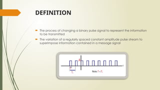
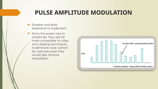
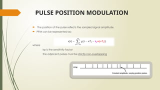
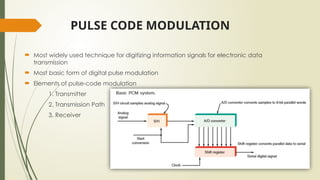
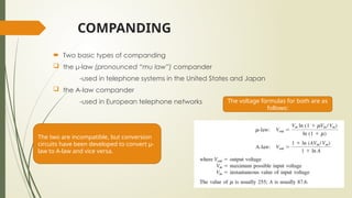
Pulse Modulation
Cervantes, Mary Joy
Neverio, Fulgencio
Estallo, Michael
BSECE-2C
DEFINITION
 The process of changing a binary pulse signal to represent the information
to be transmitted
 The variation of a regularly spaced constant amplitude pulse stream to
superimpose information contained in a message signal
TYPES OF MODULATION
 Pulse Amplitude Modulation (PAM)
 Pulse Width Modulation (PWM)
 Pulse Position Modulation (PPM)
 Pulse Code Modulation (PCM)
PULSE AMPLITUDE MODULATION
 Simplest and least
expensive to implement
 Since the pulses vary in
amplitude, they are far
more susceptible to noise,
and clipping techniques
to eliminate nose cannot
be used because they
would also remove
modulation
PULSE WIDTH MODULATION
 The width of the pulse reflects the sampled signal amplitude.
 The position of the leading edge, trailing edge or both may be modified
to reflect the changing duration of the pulse
 also known as: pulse width modulation or pulse length modulation
 PWM is wasteful of energy when the pulses are long, but the information
is only in the pulse transitions
PULSE POSITION MODULATION
 The position of the pulse reflects the sampled signal amplitude.
 PPM can be represented as:
where
kp is the sensitivity factor
the adjacent pulses must be strictly non-overlapping
PULSE CODE MODULATION
 Most widely used technique for digitizing information signals for electronic data
transmission
 Most basic form of digital pulse modulation
 Elements of pulse-code modulation
1. Transmitter
2. Transmission Path
3. Receiver
COMPANDING
 A process of signal compression and expansion that is used to overcome
problems of distortion and noise in the transmission of audio signals
 The most common means of overcoming the problems of quantizing error
and noise
COMPANDING
 Two basic types of companding
 the μ-law (pronounced “mu law”) compander
-used in telephone systems in the United States and Japan
 the A-law compander
-used in European telephone networks
The two are incompatible, but conversion
circuits have been developed to convert μ-
law to A-law and vice versa.
The voltage formulas for both are as
follows:
SAMPLE PROBLEM
Click here for the solution
SAMPLE PROBLEM
Click here for the solution

Different types of Pulse Modulation.pptx

  • 1.
    Pulse Modulation Cervantes, MaryJoy Neverio, Fulgencio Estallo, Michael BSECE-2C
  • 2.
    DEFINITION  The processof changing a binary pulse signal to represent the information to be transmitted  The variation of a regularly spaced constant amplitude pulse stream to superimpose information contained in a message signal
  • 3.
    TYPES OF MODULATION Pulse Amplitude Modulation (PAM)  Pulse Width Modulation (PWM)  Pulse Position Modulation (PPM)  Pulse Code Modulation (PCM)
  • 4.
    PULSE AMPLITUDE MODULATION Simplest and least expensive to implement  Since the pulses vary in amplitude, they are far more susceptible to noise, and clipping techniques to eliminate nose cannot be used because they would also remove modulation
  • 5.
    PULSE WIDTH MODULATION The width of the pulse reflects the sampled signal amplitude.  The position of the leading edge, trailing edge or both may be modified to reflect the changing duration of the pulse  also known as: pulse width modulation or pulse length modulation  PWM is wasteful of energy when the pulses are long, but the information is only in the pulse transitions
  • 6.
    PULSE POSITION MODULATION The position of the pulse reflects the sampled signal amplitude.  PPM can be represented as: where kp is the sensitivity factor the adjacent pulses must be strictly non-overlapping
  • 7.
    PULSE CODE MODULATION Most widely used technique for digitizing information signals for electronic data transmission  Most basic form of digital pulse modulation  Elements of pulse-code modulation 1. Transmitter 2. Transmission Path 3. Receiver
  • 8.
    COMPANDING  A processof signal compression and expansion that is used to overcome problems of distortion and noise in the transmission of audio signals  The most common means of overcoming the problems of quantizing error and noise
  • 9.
    COMPANDING  Two basictypes of companding  the μ-law (pronounced “mu law”) compander -used in telephone systems in the United States and Japan  the A-law compander -used in European telephone networks The two are incompatible, but conversion circuits have been developed to convert μ- law to A-law and vice versa. The voltage formulas for both are as follows:
  • 10.
    SAMPLE PROBLEM Click herefor the solution
  • 11.
    SAMPLE PROBLEM Click herefor the solution