Download to read offline

![Miniature Circuit-Breakers
General Data
Product overview
3/2 Siemens ET B1 T · 2007
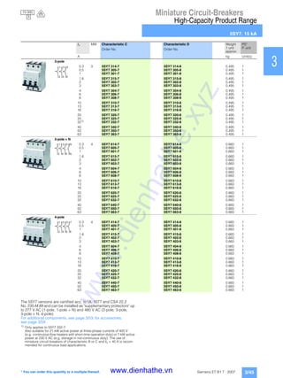
■Overview
Version Tripping
characteristic
Device
mount-
ing
depth
[mm]
Rated currents In Standards Rated switching capacity
Energy limitation class
Usage
Non-res.buildings
Res.buildings
Industry
Standard product range
5SJ6 ...-.KS B 70 10 ... 20 A EN 60898-1 ✓ ✓ ✓
5SY6 ...-.KV B 6 ... 40 A ✓ ✓ ✓
C 2 ... 40 A ✓ ✓ ✓
High-capacity product range
5SY6 B 70 2 ... 63 A EN 60898-1 ✓ ✓ ✓
C 0.3 ... 63 A ✓ ✓ ✓
D 0.3 ... 63 A ✓ ✓ ✓
5SJ4 B 6 ... 63 A UL 489
CSA 22.2 No. 5–02
14/10 kA ✓ ✓ ✓
C 0.3 ... 63 A ✓ ✓ ✓
D 0.3 ... 63 A ✓ ✓ ✓
5SY4 A 1 ... 63 A EN 60898-1 ✓ -- ✓
B 6 ... 80 A ✓ -- ✓
C 0.3 ... 80 A ✓ -- ✓
D 0.3 ... 63 A ✓ --
✓
5SY7 B 6 ... 63 A ✓ -- ✓
C 0.3 ... 63 A ✓ -- ✓
D 0.3 ... 63 A ✓ -- ✓
5SY8 C 0.3 ... 63 A EN 60947-2 25 kA ✓ -- ✓
D 0.3 ... 63 A ✓ -- ✓
UC product range
5SY5 B 70 2 ... 63 A EN 60898-2 -- -- ✓
C 0.3 ... 63 A -- -- ✓
High-current product range
5SP4 B 70 80 ... 125 A EN 60898-1 ✓ -- ✓
C 80 ... 125 A ✓ -- ✓
D 80 ... 100 A ✓ -- ✓
Power supply company product range
5SP3 E 92 16 ... 100 A DIN VDE 0645 ✓ ✓ --
Special range
8WA1 -- 12.5/22.5 0.5 ... 10 A EN 60947-2 -- -- -- ✓
Approvals VDE IMQ U UL BV DNV GL LRS CCC
Standard product range
5SJ6 ...-.KS ✓ -- -- -- -- -- -- -- --
5SY6 ...-.KV ✓ ✓ ✓ -- ✓ ✓ ✓ ✓ ✓
High-capacity product range
5SY6 ✓ ✓ ✓ -- ✓ ✓ ✓ ✓ ✓
5SJ4 -- -- -- ✓ -- -- -- -- --
5SY4 ✓ ✓ ✓ -- ✓ ✓ ✓ ✓ ✓
5SY7 ✓ ✓ ✓ -- ✓ ✓ ✓ ✓ ✓
5SY8 -- -- ✓ -- -- -- -- -- --
UC product range
5SY5 ✓ -- -- -- -- -- -- -- ✓
High-current product range
5SP4 ✓ -- ✓ -- -- -- ✓ -- ✓
Power supply company product range
5SP3 ✓ -- -- -- -- -- -- -- --
6 000
3
10 000
3
10 000
3
15 000
3
10 000
3
10 000
25 000
www.dienhathe.xyz
www.dienhathe.vn](https://image.slidesharecdn.com/dienhathe-180716022044/85/Dienhathe-com-miniature-circuit-breakers-2-320.jpg)
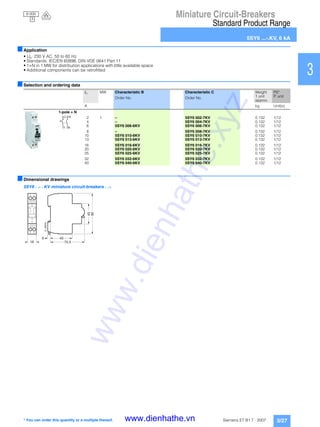
![Miniature Circuit-Breakers
General Data
Introduction
3/7Siemens ET B1 T · 2007
1
2
3
4
5
6
7
8
9
10
11
12
13
14
15
16
17
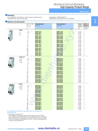
■Overview
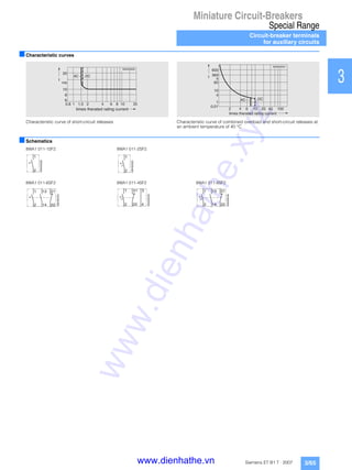
Tripping characteristics
Breaking capacity
Particular demands are made on miniature circuit-breakers with
regard to breaking capacity.
The values are standardized and are determined to the test
conditions of IEC/EN 60898 or DIN VDE 0641 Part 11.
The most common values are and .
For other test conditions, different values can be specified that are
higher those of IEC/EN 60898 or DIN VDE 0641 Part 11.
One such standard is IEC/EN 60947-2 or DIN VDE 0660 Part 101 for
circuit-breakers.
1)
D50 and D63: Icu = 15 kA.
2)
D50 and D63: Icu = 20 kA.
3)
D80 and D100: Icu = 15 kA.
Tripping characteristics at an ambient temperature of 30 °C
Tripping Standards Thermal trips Electromagnetic trips
characteristics Test currents: Test currents:
Limiting Minimum Tripping time Hold Latest Tripping time
test current test current In ≤63 A In > 63 A tripping instant
I1 I2 t I4 I5 t
A 1.13 x In > 1 h > 2 h 2 x In ≥ 0.1 s
1.45 x In < 1 h < 2 h 3 x In < 0.1 s
B IEC/EN 60898, 1.13 x In > 1 h > 2 h 3 x In ≥ 0.1 s
DIN VDE 0641 Part 11 1.45 x In < 1 h < 2 h 5 x In < 0.1 s
C 1.13 x In > 1 h > 2 h 5 x In ≥ 0.1 s
1.45 x In < 1 h < 2 h 10 x In < 0.1 s
D 1.13 x In > 1 h > 2 h 10 x In ≥ 0.1 s
1.45 x In < 1 h < 2 h 20 x In < 0.1 s
(IEC 60898: 50 x In)
6 000 10 000
Rated short-circuit capacity
IEC/EN 60898-1 IEC/EN 60947-2
1-pole 2, 3 and 4-pole 1-pole 2, 3 and 4-pole
230 V AC 400 V AC 230 V AC 400 V AC
Rated current In [A] Icn [kA] Icn [kA] Icu [kA] Icu [kA]
5SY6 0.3 ... 6 6 6 30 30
8 ... 32 6 6 15 15
40 ... 63 6 6 10 10
5SY4 0.3 ... 6 10 10 35 35
8 ... 32 10 10 20 20
40 ... 63 10 10 15 15
5SY7 0.3 ... 2 15 15 50 50
3 ... 6 15 15 40 40
8 ... 10 15 15 30 30
13 ... 32 15 15 25 25
40 ... 63 15 15 201) 201)
5SY8 0.3 ... 2 -- -- 70 70
3 ... 6 -- -- 50 50
8 ... 10 -- -- 40 40
13 ... 32 -- -- 30 30
40 ... 63 -- -- 252) 252)
5SP4 80 ... 125 10 10 203) 203)
IEC/EN 60898-2 IEC/EN 60898-2
1-pole 2-pole 1-pole 2-pole
230 V AC 400 V AC 220 V DC 440 V DC
Rated current In [A] Icn [kA] Icn [kA] Icn [kA] Icn [kA]
5SY5 0.3 ... 63 10 10 15 15
www.dienhathe.xyz
www.dienhathe.vn](https://image.slidesharecdn.com/dienhathe-180716022044/85/Dienhathe-com-miniature-circuit-breakers-7-320.jpg)
![Miniature Circuit-Breakers
General Data
Introduction
3/8 Siemens ET B1 T · 2007
Selective miniature circuit-breakers/fuses
Distribution systems are usually set up as radial networks. An over-
current protection device is required for each reduction of the con-
ductor cross-section. This produces a series connection staggered
according to rated currents, which should, if possible, be "selective".
Selectivity means that, in the event of a fault, only the protective de-
vice that is directly next to the fault in the current circuit is tripped.
This means that current paths in parallel can maintain a power flow.
In the case of miniature circuit-breakers with upstream fuses, the
selectivity limit depends largely on the current limitation and tripping
characteristics of the miniature circuit-breaker and the melting I2
t
value of the fuse.
This produces different selectivity limits for miniature circuit-break-
ers with different characteristics and rated short-circuit capacity.
The following tables provide information on the short-circuit currents
up to which selectivity exists between miniature circuit-breakers and
upstream fuse according to DIN VDE 0636 Part 21. The values spec-
ified in kA are limit values that were determined under unfavorable
test conditions. Under normal practical conditions, you can often ex-
pect considerably better values, depending on the upstream fuses.
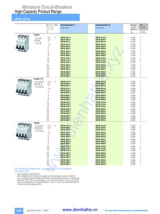
Limit values of selectivity miniature
circuit-breakers/fuses in kA
Downstream
miniature circuit-breakers
Upstream fuses
In [A] 16 A 20 A 25 A 35 A 50 A 63 A 80 A 100 A
5SY6
Characteristic B 6 0.3 0.4 0.7 1.2 3.0 3.2 • •
10 -- 0.4 0.6 1.0 2.2 3.0 5.0 •
13 -- -- 0.5 1.0 2.2 3.0 5.0 •
16 -- -- -- 1.0 2.0 2.4 4.0 •
20 -- -- -- -- 2.0 2.4 4.0 •
25 -- -- -- -- -- 2.0 3.5 •
32 -- -- -- -- -- 1.7 2.9 •
40 -- -- -- -- -- -- 2.0 4.0
50 -- -- -- -- -- -- -- 4.0
Characteristic C ≤2 0.3 0.5 1.2 1.7 • • • •
3 0.3 0.4 0.8 1.4 4.0 5.0 • •
4 0.3 0.4 0.6 1.1 3.0 4.0 • •
6 -- 0.4 0.6 1.0 2.4 3.2 • •
8 -- -- 0.5 0.9 1.4 2.6 3.1 •
10 -- -- 0.5 0.9 1.4 2.1 3.1 •
13 -- -- -- 0.8 1.3 2.0 3.0 •
16 -- -- -- 0.8 1.3 2.0 3.0 •
20 -- -- -- -- 1.3 2.0 2.7 •
25 -- -- -- -- -- 2.0 2.4 5.0
32 -- -- -- -- -- -- 2.2 4.0
40 -- -- -- -- -- -- -- 3.5
50 -- -- -- -- -- -- -- 3.0
63 -- -- -- -- -- -- -- 3.0
• r ≥ rated short-circuit capacity 5SY6 acc. to EN 60898 .6 000
www.dienhathe.xyz
www.dienhathe.vn](https://image.slidesharecdn.com/dienhathe-180716022044/85/Dienhathe-com-miniature-circuit-breakers-8-320.jpg)
![Miniature Circuit-Breakers
General Data
Introduction
3/9Siemens ET B1 T · 2007
1
2
3
4
5
6
7
8
9
10
11
12
13
14
15
16
17
Selective miniature circuit-breakers/fuses
In the event of a short-circuit, there is selectivity between the 5SY4,
5SY7, 5SP4 miniature circuit-breakers and melting fuses according
to DIN VDE 0636 Part 21 up to the specified values in kA.
Values for 5SY8 on request.
Limit values of selective line miniature
circuit-breakers/fuses in kA
Downstream Upstream fuses
Miniature circuit-breakers In [A] 16 A 20 A 25 A 35 A 50 A 63 A 80 A 100 A 125 A
5SY4, 5SY7
Characteristic A, B 6 0.3 0.4 0.8 1.4 3.2 4.5 9.0 • •
10 -- 0.4 0.7 1.2 2.5 3.5 5.0 • •
13 -- -- 0.7 1.2 2.5 3.5 5.0 • •
16 -- -- -- 1.0 2.0 2.8 4.2 9.0 •
20 -- -- -- 1.0 2.0 2.6 4.2 9.0 •
25 -- -- -- -- 1.7 2.2 3.7 7.0 •
32 -- -- -- -- 1.7 2.2 3.7 7.0 •
40 -- -- -- -- -- 1.6 2.2 4.0 6.0
50 -- -- -- -- -- -- 2.2 4.0 6.0
63 -- -- -- -- -- -- -- 3.0 5.0
Characteristic C ≤2 0.3 0.5 1.5 2.0 9.0 • • • •
3 0.3 0.4 1.1 1.6 5.0 6.0 • • •
4 0.3 0.4 0.9 1.4 3.5 5.0 9.0 • •
6 -- 0.4 0.8 1.4 2.7 4.5 6.0 • •
8 -- -- 0.6 1.2 2.2 3.5 5.0 7.0 •
10 -- -- 0.5 1.2 2.0 3.0 4.2 7.0 •
13 -- -- -- 1.0 1.6 2.4 3.4 6.0 •
16 -- -- -- 1.0 1.5 2.2 3.0 6.0 •
20 -- -- -- -- 1.3 2.2 3.0 6.0 •
25 -- -- -- -- -- 2.2 2.9 5.0 9.0
32 -- -- -- -- -- -- 2.4 4.0 7.0
40 -- -- -- -- -- -- 2.0 3.5 4.0
50 -- -- -- -- -- -- -- 3.0 4.0
63 -- -- -- -- -- -- -- 3.0 3.5
Characteristic D ≤2 0.3 0.4 1.0 1.8 5.0 7.0 • • •
3 0.3 0.4 0.9 1.5 4.0 5.0 8.0 • •
4 -- 0.4 0.8 1.2 3.0 3.8 5.5 • •
6 -- -- 0.7 1.1 2.5 3.1 4.4 8.1 •
8 -- -- -- 0.9 2.1 2.5 3.5 6.2 9.3
10 -- -- -- -- 2.1 2.5 3.5 6.2 9.3
13 -- -- -- -- -- 2.5 3.5 6.2 9.3
16 -- -- -- -- -- 2.2 3.1 5.1 7.5
20 -- -- -- -- -- -- 2.7 4.3 6.3
32 -- -- -- -- -- -- -- 4.0 5.5
40 -- -- -- -- -- -- -- 3.5 4.8
50 -- -- -- -- -- -- -- -- 4.0
63 -- -- -- -- -- -- -- -- --
• r ≥ rated short-circuit capacity 5SY4 according to EN 60898 .10 000
Limit values of selective line miniature
circuit-breakers/fuses in kA
Downstream Upstream fuses
miniature circuit-breakers In [A] 100 A 125 A 160 A 200 A 224 A 250 A
5SP4
Characteristic B 80 2.8 3.8 5.7 8.1 • •
100 -- 3.5 5.2 7.0 • •
125 -- -- 5.2 7.0 • •
Characteristic C 80 2.5 3.5 5.1 7.5 9.2 •
100 -- 3.3 4.5 6.5 8.0 •
125 -- -- 4.5 6.5 8.0 •
Characteristic D 80 2.3 3.3 4.6 6.9 8.1 •
100 -- 2.8 4.3 6.2 7.5 9.2
• r ≥ rated short-circuit capacity 5SP4 according to EN 60898 .10 000
www.dienhathe.xyz
www.dienhathe.vn](https://image.slidesharecdn.com/dienhathe-180716022044/85/Dienhathe-com-miniature-circuit-breakers-9-320.jpg)
![Miniature Circuit-Breakers
General Data
Introduction
3/10 Siemens ET B1 T · 2007
Selective miniature circuit-breakers/circuit-breakers
Distribution systems can also be set up without fuses. In such cases,
a circuit-breaker acts as an upstream protective device.
In this case, the selectivity limit depends on the level of peak
current Î let through by the miniature circuit-breaker and the tripping
current of the circuit-breaker.
The following tables show the short-circuit current in kA up to which
selectivity is guaranteed between miniature circuit-breakers and
upstream circuit-breaker according to IEC/EN 60947-2 or
DIN VDE 0660, Part 101, at 230/400 V AC, 50 Hz.
Values for 5SY8 on request.
1) In 240/415 V, 50 Hz systems, the selectivity limits are reduced by 10 %.
I > r tripping current.
Limit values of selective miniature circuit-breakers/
circuit-breakers in kA
Downstream
miniature circuit-breakers
Upstream circuit-breakers
3RV1.1 3RV1.2
In [A] 10 12 8 10 12.5 16 20 22 25
I >[A] 120 144 96 120 150 192 240 264 300
Icn [kA] 50 50 100 100 100 50 50 50 50
Selectivity limits [kA]1)
5SY4 ...-5
Characteristic A 2 6 10 0.2 0.2 -- -- 0.2 0.2 0.6 1.2 1.5
10 30 10 -- -- -- -- -- -- 0.3 0.5 0.5
16 48 10 -- -- -- -- -- -- 0.3 0.4 0.5
32 96 10 -- -- -- -- -- -- -- -- --
40 120 10 -- -- -- -- -- -- -- -- --
5SY6, 5SY4, 5SY7 ...-6
Characteristic B 6 30 6/10/15 0.2 0.2 -- -- 0.2 0.2 0.3 0.5 0.5
10 50 6/10/15 -- 0.2 -- -- 0.2 0.2 0.3 0.4 0.5
13 65 6/10/15 -- -- -- -- -- 0.2 0.2 0.4 0.4
16 80 6/10/15 -- -- -- -- -- -- 0.2 0.4 0.4
20 100 6/10/15 -- -- -- -- -- -- -- -- 0.4
25 125 6/10/15 -- -- -- -- -- -- -- -- --
32 160 6/10/15 -- -- -- -- -- -- -- -- --
40 200 6/10/15 -- -- -- -- -- -- -- -- --
50 250 6/10/15 -- -- -- -- -- -- -- -- --
5SY6, 5SY4, 5SY7 ...-7
Characteristic C 0.5 5 6/10/15 0.2 0.2 0.1 0.1 0.2 0.2 0.5 0.6 0.6
1 10 6/10/15 0.2 0.2 0.1 0.1 0.2 0.2 0.5 0.6 0.6
1.6 16 6/10/15 0.2 0.2 0.1 0.1 0.2 0.2 0.5 0.6 0.6
2 20 6/10/15 0.2 0.2 0.1 0.1 0.2 0.2 0.5 0.6 0.6
3 30 6/10/15 -- 0.2 -- -- 0.2 0.2 0.3 0.4 0.5
4 40 6/10/15 -- 0.2 -- -- 0.2 0.2 0.3 0.4 0.5
6 60 6/10/15 -- 0.2 -- -- 0.2 0.2 0.3 0.4 0.5
8 80 6/10/15 -- 0.2 -- -- 0.2 0.2 0.2 0.4 0.4
10 100 6/10/15 -- 0.2 -- -- 0.2 0.2 0.2 0.4 0.4
13 130 6/10/15 -- -- -- -- -- 0.2 0.2 0.4 0.4
16 160 6/10/15 -- -- -- -- -- -- 0.2 0.4 0.4
20 200 6/10/15 -- -- -- -- -- -- -- -- 0.4
25 250 6/10/15 -- -- -- -- -- -- -- -- --
32 320 6/10/15 -- -- -- -- -- -- -- -- --
40 400 6/10/15 -- -- -- -- -- -- -- -- --
50 500 6/10/15 -- -- -- -- -- -- -- -- --
63 630 6/10/15 -- -- -- -- -- -- -- -- --
5SY6, 5SY4, 5SY7 ...-8
Characteristic D 2 40 6/10/15 -- -- -- -- 0.2 0.2 0.4 0.6 0.6
6 120 6/10/15 -- -- -- -- -- -- 0.3 0.4 0.4
10 200 6/10/15 -- -- -- -- -- -- 0.2 0.4 0.4
16 320 6/10/15 -- -- -- -- -- -- -- -- --
32 640 6/10/15 -- -- -- -- -- -- -- -- --
40 800 6/10/15 -- -- -- -- -- -- -- -- --
50 1 000 6/10/15 -- -- -- -- -- -- -- -- --
www.dienhathe.xyz
www.dienhathe.vn](https://image.slidesharecdn.com/dienhathe-180716022044/85/Dienhathe-com-miniature-circuit-breakers-10-320.jpg)
![Miniature Circuit-Breakers
General Data
Introduction
3/11Siemens ET B1 T · 2007
1
2
3
4
5
6
7
8
9
10
11
12
13
14
15
16
17
Selective miniature circuit-breakers/circuit-breakers
In the event of a short-circuit, there is selectivity between miniature
circuit-breakers and circuit-breakers according to IEC/EN 60947-2
or DIN VDE 0660 Part 101 up to the specified values in kA.
In 240/415 V, 50 Hz systems, the selectivity limits are reduced by 10 %.
I > r tripping current.
Limit values of selective line miniature circuit-breakers/fuses in kA
Downstream
miniature circuit-breakers
Upstream circuit-breakers
3RV1.3
In [A] 16 20 25 32 40 45 50
I >[A] 192 240 300 384 480 540 600
Icn [kA] 50 50 50 50 50 50 50
Selectivity limits [kA]1)
5SY4...-5
Characteristic A 2 6 10 0.2 0.8 1.2 2.5 3 6 6
10 30 10 0.2 0.4 0.5 0.6 0.8 1 1.2
16 48 10 -- 0.3 0.4 0.6 0.8 0.8 1
32 96 10 -- -- -- -- 0.6 0.8 0.8
40 120 10 -- -- -- -- -- -- 0.8
5SY4, 5SY7...-6
Characteristic B 6 30 6/10/15 0.2 0.3 0.5 0.6 0.8 1 1.2
10 50 6/10/15 0.2 0.3 0.4 0.6 0.8 1 1.2
13 65 6/10/15 0.2 0.3 0.4 0.6 0.8 1 1
16 80 6/10/15 -- 0.3 0.4 0.6 0.8 1 1
20 100 6/10/15 -- -- 0.4 0.6 0.8 1 1
25 125 6/10/15 -- -- -- 0.5 0.6 0.8 0.8
32 160 6/10/15 -- -- -- -- 0.6 0.8 0.8
40 200 6/10/15 -- -- -- -- -- -- 0.8
50 250 6/10/15 -- -- -- -- -- -- --
5SY6, 5SY4, 5SY7...-7
Characteristic C 0.5 5 6/10/15 0.3 0.5 0.6 1 1 1.5 3
1 10 6/10/15 0.3 0.5 0.6 1 1 1.5 3
1.6 16 6/10/15 0.3 0.5 0.6 1 1 1.5 3
2 20 6/10/15 0.3 0.5 0.6 1 1 1.5 3
3 30 6/10/15 0.2 0.3 0.4 0.6 0.8 1 1
4 40 6/10/15 0.2 0.3 0.4 0.6 0.8 1 1
6 60 6/10/15 0.2 0.3 0.4 0.6 0.8 1 1
8 80 6/10/15 0.2 0.2 0.4 0.6 0.6 0.8 1
10 100 6/10/15 0.2 0.2 0.4 0.6 0.6 0.8 1
13 130 6/10/15 0.2 0.2 0.4 0.6 0.6 0.8 1
16 160 6/10/15 -- 0.2 0.4 0.6 0.6 0.8 1
20 200 6/10/15 -- -- 0.4 0.6 0.6 0.8 1
25 250 6/10/15 -- -- -- 0.5 0.6 0.8 0.8
32 320 6/10/15 -- -- -- -- 0.6 0.8 0.8
40 400 6/10/15 -- -- -- -- -- -- 0.8
50 500 6/10/15 -- -- -- -- -- -- --
63 630 6/10/15 -- -- -- -- -- -- --
5SY6, 5SY4, 5SY7 ...-8
Characteristic D 2 40 6/10/15 0.3 0.5 0.6 0.8 1.2 1.5 1.5
6 120 6/10/15 0.2 0.3 0.4 0.6 0.8 1 1
10 200 6/10/15 -- 0.3 0.4 0.5 0.6 0.8 0.8
16 320 6/10/15 -- -- -- 0.5 0.6 0.6 0.8
32 640 6/10/15 -- -- -- -- -- 0.6 0.6
40 800 6/10/15 -- -- -- -- -- -- --
50 1 000 6/10/15 -- -- -- -- -- -- --
www.dienhathe.xyz
www.dienhathe.vn](https://image.slidesharecdn.com/dienhathe-180716022044/85/Dienhathe-com-miniature-circuit-breakers-11-320.jpg)
![Miniature Circuit-Breakers
General Data
Introduction
3/12 Siemens ET B1 T · 2007
Selective miniature circuit-breakers/circuit-breakers
In the event of a short-circuit, there is selectivity between miniature
circuit-breakers and circuit-breakers according to IEC/EN 60947-2
or DIN VDE 0660 Part 101 up to the specified values in kA.
Values for 5SY8 on request.
1)
In 240/415 V, 50 Hz systems, the selectivity limits are reduced by 10 %.
I > r tripping current.
Limit values of selective miniature circuit-breakers/
circuit-breakers in kA
Downstream
miniature circuit-breakers
Upstream circuit-breakers
3RV1.4
In [A] 16 20 25 32 40 50 63 75 90 100
I >[A] 192 240 300 384 480 600 756 900 1080 1140
Icn [kA] 100 100 100 100 100 100 100 100 100 100
Selectivity limits [kA]1)
5SY4 ...-5
Characteristic A 2 6 10 0.5 0.8 1.5 2.5 3 6/7.5 6/10 6/10 6/10 6/10
10 30 10 0.3 0.4 0.5 0.6 0.8 1.2 1.5 2.5 3 4
16 48 10 -- 0.3 0.5 0.6 0.6 1 1.5 2 3 3
32 96 10 -- -- -- -- 0.6 0.8 1.5 2 2.5 3
40 120 10 -- -- -- -- -- 0.8 1.2 1.5 2 2
5SY6, 5SY4, 5SY7...-6
Characteristic B 6 30 6/10/15 0.2 0.4 0.5 0.6 0.8 1.2 2 3 6/10/15 6/10/15
10 50 6/10/15 0.2 0.3 0.5 0.6 0.8 1 1.5 2.5 4 4
13 65 6/10/15 0.2 0.3 0.5 0.6 0.8 1 1.5 2 3 3
16 80 6/10/15 -- 0.3 0.5 0.6 0.8 1 1.5 2 3 3
20 100 6/10/15 -- -- 0.5 0.6 0.8 1 1.5 2 3 3
25 125 6/10/15 -- -- -- 0.5 0.8 0.8 1.5 2 3 3
32 160 6/10/15 -- -- -- -- 0.6 0.8 1.5 2 3 3
40 200 6/10/15 -- -- -- -- 0.6 0.8 1.2 1.5 2.5 2.5
50 250 6/10/15 -- -- -- -- -- -- 1.2 1.5 2.5 2.5
5SY6, 5SY4, 5SY7...-7
Characteristic C 0.5 5 6/10/15 0.4 0.6 0.8 0.8 1 3 6/10/15 6/10/15 6/10/15 6/10/15
1 10 6/10/15 0.4 0.6 0.8 0.8 1 3 6/10/15 6/10/15 6/10/15 6/10/15
1.6 16 6/10/15 0.4 0.6 0.8 0.8 1 3 6/10/15 6/10/15 6/10/15 6/10/15
2 20 6/10/15 0.4 0.6 0.8 0.8 1 3 6/10/15 6/10/15 6/10/15 6/10/15
3 30 6/10/15 0.2 0.3 0.5 0.6 0.8 1 2 2.5 5 5
4 40 6/10/15 0.2 0.3 0.5 0.6 0.8 1 2 2.5 5 5
6 60 6/10/15 0.2 0.3 0.5 0.6 0.8 1 2 2.5 5 5
8 80 6/10/15 0.2 0.3 0.4 0.6 0.6 1 1.5 2 3 3
10 100 6/10/15 0.2 0.3 0.4 0.6 0.6 1 1.5 2 3 3
13 130 6/10/15 0.2 0.3 0.4 0.6 0.6 1 1.5 2 3 3
16 160 6/10/15 -- 0.3 0.4 0.6 0.6 1 1.5 2 3 3
20 200 6/10/15 -- -- 0.4 0.6 0.6 1 1.5 2 3 3
25 250 6/10/15 -- -- -- 0.5 0.6 0.8 1.2 1.5 2.5 2.5
32 320 6/10/15 -- -- -- -- 0.6 0.8 1.2 1.5 2.5 2.5
40 400 6/10/15 -- -- -- -- -- 0.6 1 1.5 2 2
50 500 6/10/15 -- -- -- -- -- -- 1 1.2 1.5 2
63 630 6/10/15 -- -- -- -- -- -- -- -- 1.5 1.5
5SY6, 5SY4, 5SY7...-8
Characteristic D 2 40 6/10/15 0.4 0.5 0.6 0.8 1 1.5 3 4 6/10/15 6/10/15
6 120 6/10/15 0.2 0.3 0.4 0.6 0.6 1 1.5 2.5 3 3
10 200 6/10/15 -- 0.3 0.4 0.5 0.6 0.8 1.5 2 3 3
16 320 6/10/15 -- -- -- 0.5 0.6 0.8 1.2 1.5 2.5 2.5
32 640 6/10/15 -- -- -- -- -- 0.6 1 1.5 2 2
40 800 6/10/15 -- -- -- -- -- -- 1 1.2 1.5 1.5
50 1000 6/10/15 -- -- -- -- -- -- 1 1.2 1.5 1.5
5SP4...-7
Characteristic C 80 1600 10 -- -- -- -- -- -- -- -- -- 1.2
100 2000 10 -- -- -- -- -- -- -- -- -- --
5SP4...-8
Characteristic D 80 1600 10 -- -- -- -- -- -- -- -- -- --
100 2000 10 -- -- -- -- -- -- -- -- -- --
www.dienhathe.xyz
www.dienhathe.vn](https://image.slidesharecdn.com/dienhathe-180716022044/85/Dienhathe-com-miniature-circuit-breakers-12-320.jpg)
![Miniature Circuit-Breakers
General Data
Introduction
3/13Siemens ET B1 T · 2007
1
2
3
4
5
6
7
8
9
10
11
12
13
14
15
16
17
Selective miniature circuit-breakers/circuit-breakers
In the event of a short-circuit, there is selectivity between miniature
circuit-breakers and circuit-breakers according to IEC/EN 60947-2
or DIN VDE 0660 Part 101 up to the specified values in kA.
Values for 5SY8 on request.
T r full selectivity up to rated breaking capacity Icn of the downstream
protective device
1)
In 240/415 V, 50 Hz systems, the selectivity limits are reduced by 10 %.
The selectivity limits for adjustable releases apply to the maximum value,
In = rated current.
I > r tripping current.
Limit values of selective miniature circuit-breakers/
circuit-breakers in kA
Downstream
miniature circuit-
breakers
Upstream circuit-breakers
3VL1, TM 3VL2, TM
non-adjustable adjustable
In [A] 50 63 80 100 125 160 50 63 80 100 125 160
I >[A] 500 630 800 1000 1250 1600 400 500 630 800 1000 1280
Icn [kA] 40/70/
100
40/70/
100
40/70/
100
40/70/
100
40/70/
100
40/70/
100
40/70/
100
40/70/
100
40/70/
100
40/70/
100
40/70/
100
40/70/
100
Selectivity limits [kA]1)
5SY6, 5SY4, 5SY7
Characteristic A 2 6 10 10 10 10 10 10 10 10 10 10 10 10 10
10 30 10 1.6 4.7 6 10 10 10 2.5 4 4 4.5 4.9 10
16 48 10 1.4 4.7 6 10 10 10 2.3 3.7 3.7 4.4 5 10
32 96 10 1.2 3.6 4.6 10 10 10 1.8 3 3 3.5 3.7 6
40 120 10 1 2.5 3.1 6 10 10 1.5 2 2 2.4 2.7 3.2
Characteristic B 6 30 6/10/15 5.5 5.5 T T T T 2.5 2.5 5.1 7.3 T T
10 50 6/10/15 3.1 3.1 6.7 6.7 6.7 6/12/4 2.0 2.0 3.0 3.9 5.0 8.6
13 65 6/10/15 2.5 2.5 5.0 5.0 5.0 8.0 1.5 1.5 3.1 3.4 4.5 5.8
16 80 6/10/15 2.5 2.5 4.4 4.4 4.4 7.2 1.5 1.5 2.0 3.1 4.0 5.1
20 100 6/10/15 2.0 2.0 4.3 4.3 4.3 6.6 1.5 1.5 2.0 2.5 3.9 5.0
25 125 6/10/15 2.0 2.0 3.9 3.9 3.9 6.1 1.5 1.5 2.0 2.1 3.4 4.6
32 160 6/10/15 2.0 2.0 3.7 3.7 3.7 5.0 1.5 1.5 2.0 2.1 3.4 4.8
40 200 6/10/15 2.0 2.0 3.7 3.7 3.7 5.0 1.2 1.2 2.0 2.1 3.3 4.3
50 250 6/10/15 -- 1.5 3.2 3.2 3.2 4.0 -- -- 1.5 2.0 2.5 3.6
Characteristic C 0.5 5 6/10/15 T T T T T T T T T T T T
1 10 6/10/15 T T T T T T T T T T T T
1.5 15 6/10/15 T T T T T T T T T T T T
2 20 6/10/15 T T T T T T T T T T T T
3 30 6/10/15 3.2 3.2 T T T T 2.5 T T T T T
4 40 6/10/15 3.2 3.2 T T T T 2.5 T T T T T
6 60 6/10/15 3.2 3.2 7 7 7 6/10/
13.9
2.5 2.5 5.1 7.3 T T
8 80 6/10/15 2.5 2.5 5.4 5.4 5.4 6/9/2 2.3 3.7 3.8 3.9 5.6 8.6
10 100 6/10/15 2.5 2.5 5.4 5.4 5.4 6/9/2 2.0 2.0 3.0 3.4 5.6 8.6
13 130 6/10/15 2.5 2.5 4.3 4.3 4.3 7.1 1.5 1.5 2.5 3.4 4.5 5.8
16 160 6/10/15 2.0 2.5 4.0 4.0 4.0 7.1 1.5 1.5 2.5 3.1 4.0 5.1
20 200 6/10/15 2.0 2.0 3.7 3.7 3.7 6.3 1.5 1.5 2.0 2.5 3.9 5.0
25 250 6/10/15 2.0 2.0 3.6 3.6 3.6 5.5 1.5 1.5 2.0 2.5 3,.5 4.6
32 320 6/10/15 2.0 2.0 3.5 3.5 3.5 5.5 1.5 1.5 2.0 2.5 3.4 4.5
40 400 6/10/15 1.5 1.5 3.3 3.3 3.3 5.1 1.2 1.2 2.0 2.5 3.3 4.3
50 500 6/10/15 -- 1.5 3.1 3.1 3.1 4.0 -- -- 1.5 2.5 2.5 3.6
Characteristic D 2 40 6/10/15 2.4 6 6 6 6 6 4.2 6 6 6 6 6
6 120 6/10/15 1.4 1.4 4.8 5 6 6 2.3 4.1 4.2 4.2 4.3 6
10 200 6/10/15 1.3 1.3 4.5 5 6 6 1.9 3.7 3.7 3.7 4 6
16 320 6/10/15 1.1 1.1 3.2 3.2 3.2 4.0 1.7 3.3 3.7 3.3 3.5 4.7
32 640 6/10/15 -- -- 2.3 2.3 2.3 4.0 -- -- -- 2.4 2.7 3.7
40 800 6/10/15 -- -- -- 2.1 2.1 3.8 -- -- -- -- 1.5 3
50 1000 6/10/15 -- -- -- -- 2.0 2.8 -- -- -- -- -- 2.6
5SP4
Characteristic C 80 800 10 -- -- -- 1.0 1.2 2.0 -- -- -- -- 1.2 1.5
100 1000 10 -- -- -- -- 1.2 1.5 -- -- -- -- -- 1.5
Characteristic D 80 1600 10 -- -- -- -- -- -- -- -- -- -- -- --
100 1200 10 -- -- -- -- -- -- -- -- -- -- -- --
www.dienhathe.xyz
www.dienhathe.vn](https://image.slidesharecdn.com/dienhathe-180716022044/85/Dienhathe-com-miniature-circuit-breakers-13-320.jpg)
![Miniature Circuit-Breakers
General Data
Introduction
3/14 Siemens ET B1 T · 2007
Selective miniature circuit-breakers/circuit-breakers
In the event of a short-circuit, there is selectivity between miniature
circuit-breakers and circuit-breakers according acc. to IE/EN 60947-2
or DIN VDE 0660 Part 101 up to the specified values in kA.
Values for 5SY8 on request.
T r full selectivity up to rated breaking capacity Icn of the downstream
protective device
1)
In 240/415 V, 50 Hz systems, the selectivity limits are reduced by 10 %.
The selectivity limits for adjustable releases apply to the maximum value,
In = rated current.
I > r tripping current.
Limit values of selective miniature circuit-
breakers/circuit-breakers in kA
Downstream
miniature
circuit-breakers
Upstream circuit-breakers
3VL3,
TM
3VL4,
TM
3VL6,
ETU
3VL7.
ETU
3VL8,
ETU
3WN1 3WN6
In [A] 200 250 200 250 315 400 315 400- 400- 800- 315- 315-
800 1250 2500 6300 3200
I >[A] 2000 2500 2000 2500 3150 4000 3200 1575- 15000 20000 3780- 3780-
6400 75600 48000
Icn [kA] 40-100 40-100 45-100 45-100 45-100 45-100 45-100 45-100 50-100 70/100 65-100 65/75
Selectivity limits [kA]1)
5SY6, 5SY4, 5SY7
Characteristic A
2 6 10 T T T T T T T T T T T T
10 30 10 T T T T T T T T T T T T
16 48 10 T T T T T T T T T T T T
32 96 10 T T T T T T T T T T T T
40 120 10 T T T T T T T T T T T T
Characteristic B
6 30 6/10/15 T T T T T T T T T T T T
10 50 6/10/15 T T T T T T T T T T T T
13 65 6/10/15 T T T T T T T T T T T T
16 80 6/10/15 T T T T T T T T T T T T
20 100 6/10/15 T T T T T T T T T T T T
25 125 6/10/15 T T T T T T T T T T T T
32 160 6/10/15 T T T T T T T T T T T T
40 200 6/10/15 6 6 6 T T T T T T T T T
50 250 6/10/15 6 6 6/10/
14.1
T T T T T T T T T
Characteristic C
0.5 5 6/10/15 T T T T T T T T T T T T
1 10 6/10/15 T T T T T T T T T T T T
1.5 15 6/10/15 T T T T T T T T T T T T
2 20 6/10/15 T T T T T T T T T T T T
3 30 6/10/15 T T T T T T T T T T T T
4 40 6/10/15 T T T T T T T T T T T T
6 60 6/10/15 T T T T T T T T T T T T
8 80 6/10/15 T T T T T T T T T T T T
10 100 6/10/15 T T T T T T T T T T T T
13 130 6/10/15 T T T T T T T T T T T T
16 160 6/10/15 T T T T T T T T T T T T
20 200 6/10/15 T T T T T T T T T T T T
25 250 6/10/15 T T T T T T T T T T T T
32 320 6/10/15 6/10/11 T T T T T T T T T T T
40 400 6/10/15 6/10 T T T T T T T T T T T
50 500 6/10/15 6/10 T T T T T T 6/10/
14.2
T T T T
Characteristic D
2 40 6/10/15 T T T T T T T T T T T T
6 120 6/10/15 T T T T T T T T T T T T
10 200 6/10/15 T T T T T T T T T T T T
16 320 6/10/15 T T T T T T T T T T T T
32 640 6/10/15 T T T T T T T T T T T T
40 800 6/10/15 T T T T T T T T T T T T
50 1000 6/10/15 T T T T T T T T T T T T
5SP4
Characteristic C
80 800 10 3 3 3 3 3 6 8 T T T T T
100 1000 10 3 3 3 3 3 5 6 T T T T T
Characteristic D
80 1600 10 3 3 2.5 3 3 5 6 T T T T T
100 2000 10 -- 2.5 -- 3 3 5 6 T T T T T
www.dienhathe.xyz
www.dienhathe.vn](https://image.slidesharecdn.com/dienhathe-180716022044/85/Dienhathe-com-miniature-circuit-breakers-14-320.jpg)
![Miniature Circuit-Breakers
General Data
Introduction
3/15Siemens ET B1 T · 2007
1
2
3
4
5
6
7
8
9
10
11
12
13
14
15
16
17
Selective miniature circuit-breakers/miniature circuit-breakers
Within narrow limits, miniature circuit-breakers also offer selectivity
between circuit-breakers in a fuseless distribution board.
This depends on the let-through peak current Î of the downstream
miniature circuit-breaker and on the tripping current of the upstream
miniature circuit-breaker.
The following table shows the short-circuit current in kA up to which
there is selectivity between series-connected miniature circuit-
breakers at 230 V AC.
T r full selectivity up to rated breaking capacity Icn of the downstream
protective device
1) In 240/415 V, 50 Hz systems, the selectivity limits are reduced by 10 %.
The selectivity limits for adjustable releases apply to the maximum value,
In = rated current.
I > r tripping current.
Limit values of selective miniature circuit-breakers/
circuit-breakers in kA
Downstream
miniature circuit-breakers
Upstream miniature circuit-breakers
5SY4 ...-7
Characteristic C
5SP4 ...-7
Characteristic C
5SP4 ...-8
Characteristic D
In [A] 20 25 32 40 50 80 100 80 100
I >[A] 200 250 320 400 500 800 1000 1200 1500
Icn [kA] 10 10 10 10 10 10 10 10 10
Selectivity limits [kA]1)
5SY
Characteristic B 6 30 6/10/15 0.2 0.2 0.3 0.5 0.5 0.8 1.5 3 5
10 50 6/10/15 0.2 0.2 0.3 0.5 0.5 0.8 1.2 3 4
13 65 6/10/15 0.2 0.2 0.3 0.4 0.5 0.8 1.2 2 3
16 80 6/10/15 0.2 0.2 0.3 0.4 0.5 0.8 1.2 2 3
20 100 6/10/15 -- 0.2 0.3 0.4 0.5 0.8 1.2 2 3
25 125 6/10/15 -- -- -- 0.4 0.4 0.6 1.2 1.5 3
32 160 6/10/15 -- -- -- 0.4 0.4 0.6 1.2 1.5 3
40 200 6/10/15 -- -- -- -- 0.4 0.6 1.2 1.5 2.5
50 250 6/10/15 -- -- -- -- -- 0.6 1 1.5 2.5
Characteristic C 0.5 5 6/10/15 0.2 0.3 0.5 0.8 0.8 1.2 4 T T
1 10 6/10/15 0.2 0.3 0.5 0.8 0.8 1.2 4 T T
1.5 15 6/10/15 0.2 0.3 0.5 0.8 0.8 1.2 4 T T
2 20 6/10/15 0.2 0.3 0.5 0.8 0.8 1.2 4 T T
3 30 6/10/15 0.2 0.2 0.3 0.5 0.5 0.8 1.5 3 4
4 40 6/10/15 0.2 0.2 0.3 0.5 0.5 0.8 1.5 3 4
6 60 6/10/15 0.2 0.2 0.3 0.5 0.5 0.8 1.5 3 4
8 80 6/10/15 0.2 0.2 0.3 0.4 0.4 0.6 1.2 2.5 3
10 100 6/10/15 0.2 0.2 0.3 0.4 0.4 0.6 1.2 2.5 3
13 130 6/10/15 0.2 0.2 0.3 0.4 0.4 0.6 1.2 2 3
16 160 6/10/15 0.2 0.2 0.3 0.4 0.4 0.6 1.2 2 3
20 200 6/10/15 -- 0.2 0.3 0.4 0.4 0.6 1.2 2 3
25 250 6/10/15 -- -- -- 0.3 0.4 0.6 1 1.5 2.5
32 320 6/10/15 -- -- -- 0.3 0.4 0.6 1 1.5 2.5
40 400 6/10/15 -- -- -- -- -- -- 0.8 1.5 2
50 500 6/10/15 -- -- -- -- -- -- 0.8 1.5 2
63 630 6/10/15 -- -- -- -- -- -- 0.8 1.2 1.5
www.dienhathe.xyz
www.dienhathe.vn](https://image.slidesharecdn.com/dienhathe-180716022044/85/Dienhathe-com-miniature-circuit-breakers-15-320.jpg)
![Miniature Circuit-Breakers
General Data
Introduction
3/16 Siemens ET B1 T · 2007
Back-up protection miniature circuit-breakers/fuses
If the maximum short-circuit current of the miniature circuit-breaker
at the installation site is unknown, or if the specified rated short-
circuit capacity is exceeded, an additional protective device must
be connected upstream as back-up protection to prevent overload-
ing of the miniature circuit-breaker. This is usually a fuse.
The following table shows the short-circuit currents in kA up to which
back-up protection is guaranteed when using fuses according to
DIN VDE 0636 Part 21.
Limit values of back-up protection
miniature circuit-breakers/fuses in kA
Downstream
miniature circuit-breakers
Upstream fuses
In [A] 50 A 63 A 80 A 100 A 125 A 160 A
5SY6
0.3 ... 4 no back-up protection required up to 50 kA
6 50 50 50 50 50 35
8 50 50 50 50 50 35
10 50 50 50 50 50 35
13 50 50 50 35 35 30
16 50 50 50 35 30 30
20 50 50 50 35 25 25
25 50 50 50 35 30 25
32 50 50 50 35 30 25
40 50 50 50 50 25 15
50 50 50 50 50 25 15
63 50 50 35 25 25 15
5SY4, 5SY7
0.3 ... 6 no back-up protection required
8 50 50 50 50 45 45
10 50 50 50 50 45 45
13 50 50 50 45 40 35
16 50 50 50 45 40 35
20 50 50 50 40 35 30
25 50 50 50 40 35 30
32 50 50 50 45 40 30
40 50 50 50 45 40 30
50 50 50 50 40 35 25
63 50 50 45 40 35 25
Test circuit data: Test cycle:
Up = 250 V according to EN 60947 – 2 (0 – C0)
p.f. = 0.3 ... 0.5
I2_06355a
www.dienhathe.xyz
www.dienhathe.vn](https://image.slidesharecdn.com/dienhathe-180716022044/85/Dienhathe-com-miniature-circuit-breakers-16-320.jpg)
![Miniature Circuit-Breakers
General Data
Introduction
3/17Siemens ET B1 T · 2007
1
2
3
4
5
6
7
8
9
10
11
12
13
14
15
16
17
Back-up protection miniature circuit-breakers/circuit-breakers
If miniature circuit-breakers are installed in fuseless distribution
boards, circuit-breakers acc. to IEC/EN 60947-2 or DIN VDE 0660
Part 101 must be used as back-up protection.
The following tables show the short-circuit currents – in kA –
up to which back-up protection is guaranteed when using circuit-
breakers.
Limit values of back-up protection
miniature circuit-breakers/
circuit-breakers in kA
Downstream
miniature circuit-breakers
Upstream circuit-breakers
3VL1
non-adjustable
3VL2
adjustable
In [A] 50 63 80 100 125 160 50 63 80 100 125 160
I >[A] 500 630 800 1000 1250 1600 400 500 630 800 1000 1280
Icn [kA] 40/70/
100
40/70/
100
40/70/
100
40/70/
100
40/70/
100
40/70/
100
40/70/
100
40/70/
100
40/70/
100
40/70/
100
40/70/
100
40/70/
100
Back-up protection up to kA
5SY6
Characteristic B,
Characteristic C
0.3 ... 6 6 35 35 35 35 35 35 35 35 35 35 35 35
8 ... 32 6 25 25 25 25 25 25 25 25 25 25 25 25
40 ... 63 6 20 20 20 20 20 20 20 20 20 20 20 20
5SY4
Characteristic A,
Characteristic B,
Characteristic C,
Characteristic D
0.3 ... 6 10/15 40 40 40 40 40 40 40 40 40 40 40 40
8 ... 32 10/15 30 30 30 30 30 30 30 30 30 30 30 30
40 ... 63 10/15 25 25 25 25 25 25 25 25 25 25 25 25
5SY7
Characteristic B,
Characteristic C
0.3 ... 2 10/15 50 50 50 50 50 50 50 50 50 50 50 50
3 ... 10 10/15 45 45 45 45 45 45 45 45 45 45 45 45
13 ... 32 10/15 40 40 40 40 40 40 40 40 40 40 40 40
40 ... 63 10/15 35 35 35 35 35 35 35 35 35 35 35 35
Characteristic D 0.3 ... 2 50 50 50 50 50 50 50 50 50 50 50 50
3 ... 10 45 45 45 45 45 45 45 45 45 45 45 45
10 ... 32 40 40 40 40 40 40 40 40 40 40 40 40
40 35 35 35 35 35 35 35 35 35 35 35 35
50 ... 63 30 30 30 30 30 30 30 30 30 30 30 30
Downstream
miniature circuit-breakers
Upstream circuit-breakers
3VL3 3VL4 3VL6 3VL7 3VL8 3WN1/
3WS1
In [A] 200 250 200 250 315 400 315 ...
630
400 ...
1250
1600 ...
2000
315 ...
6300
I >[A] 2000 2500 2000 2500 3150 4000 3200 ...
6300
15000 20000 3780
...
75600
Icn [kA] 40/70/
100
40/70/
100
45/70/
100
45/70/
100
45/70/
100
45/70/
100
45/70/
100
50/70/
100
70/100 65 ...
100
Back-up protection up to kA
5SY6
Characteristic B,
Characteristic C,
Characteristic D
0.3 ... 6 6 30 30 30 30 30 30 30 30 30 30
8 ... 32 6 15 15 15 15 15 15 15 15 15 15
40 ... 63 6 10 10 10 10 10 10 10 10 10 10
5SY4
Characteristic A,
Characteristic B,
Characteristic C,
Characteristic D
0.3 ... 6 10/15 40 40 40 40 40 40 40 40 40 40
8 ... 32 10/15 30 30 30 30 30 30 30 30 30 30
42 ... 63 10/15 25 25 25 25 25 25 25 25 25 25
5SY7
Characteristic B,
Characteristic C
0.3 ... 2 10/15 50 50 50 50 50 50 50 50 50 50
3 ... 10 10/15 45 45 45 45 45 45 45 45 45 45
13 ... 32 10/15 35 35 35 35 35 35 35 35 35 35
40 ... 63 10/15 35 35 35 35 35 35 35 35 35 35
Characteristic D 0.3 ... 2 10/15 50 50 50 50 50 50 50 50 50 50
3 ... 10 10/15 45 45 45 45 45 45 45 45 45 45
10 ... 32 10/15 40 40 40 40 40 40 40 40 40 40
40 10/15 35 35 35 35 35 35 35 35 35 35
50 ... 63 10/15 30 30 30 30 30 30 30 30 30 30
I2_06356a
www.dienhathe.xyz
www.dienhathe.vn](https://image.slidesharecdn.com/dienhathe-180716022044/85/Dienhathe-com-miniature-circuit-breakers-17-320.jpg)
![Miniature Circuit-Breakers
General Data
Introduction
3/18 Siemens ET B1 T · 2007
Internal resistance and power loss Data per pole (loaded with In)
In [A] Type A Type B Type C Type D
R1 Pv R1 Pv R1 Pv R1 Pv
mΩ W mΩ W mΩ W mΩ W
5SY6, 5SY4, 5SY7, 5SY8, 5SY5
0.3 -- -- -- -- 10500 0.9 10200 1
0.5 -- -- -- -- 3400 0.9 3120 0.8
1 1955 2.0 -- -- 1 210 1.2 1030 1.0
1.6 786 2.0 -- -- 459 1.2 409 1.1
2 510 2.0 375 1.5 295 1.2 292 1.2
3 205 1.9 -- -- 137 1.2 131 1.2
4 134 2.1 91 1.45 81 1.3 73 1.2
5 -- -- -- -- 86 2.1 -- --
6 58 2.1 55 2.0 44 1.6 43 1.6
8 27 1.7 -- -- 14 0.9 12 0.7
10 18.1 1.8 13 1.3 10 1.0 8.4 0.8
13 11.4 1.9 9.5 1.6 8.0 1.4 8.0 1.4
15 -- -- -- -- 6.3 1.4 -- --
16 8.4 2.2 6.6 1.7 5.9 1.5 5.8 1.5
20 6.2 2.5 5.2 2.1 4.0 1.6 3.8 1.5
25 4.6 2.9 3.4 2.2 3.3 2.1 3.0 1.9
30 -- -- -- -- 2.4 2.2 -- --
32 3 3.1 2.3 2.4 2.4 2.5 1.9 2.0
35 -- -- -- -- 2.0 2.4 -- --
40 2.2 3.5 2.1 3.4 2.1 3.3 1.8 2.8
45 -- -- -- -- 1.4 2.9 -- --
50 1.7 4.3 1.5 3.8 1.4 3.5 1.4 3.5
60 -- -- -- -- 1.1 4.1 -- --
63 1.5 5.9 1.4 5.4 1.1 4.4 1.1 4.4
80 -- -- 1.0 6.4 1.0 6.4 -- --
5SP4
80 -- -- 1.1 7.0 1.1 6.7 1.1 6.7
100 -- -- 0.8 8.0 0.88 8 0.8 8
125 -- -- 0.7 10.1 0.7 10.9 -- --
Correction factor for power dissipation
• Direct current and alternating current up to 60 Hz x 1.0
• Alternating current 200 Hz x 1.1
400 Hz x 1.15
1 100 Hz x 1.3
www.dienhathe.xyz
www.dienhathe.vn](https://image.slidesharecdn.com/dienhathe-180716022044/85/Dienhathe-com-miniature-circuit-breakers-18-320.jpg)
![Miniature Circuit-Breakers
General Data
Introduction
3/19Siemens ET B1 T · 2007
1
2
3
4
5
6
7
8
9
10
11
12
13
14
15
16
17
Personnel safety with miniature circuit-breakers
According to DIN VDE 0100 Part 410, in order to protect against dan-
gerous leakage currents in the TN system, the cross-sections of the
conductor, or its distance from the protective device, must be
dimensioned such that if a fault with negligible impedance (i.e. short-
circuit) occurs at any point between a phase conductor and a PE
conductor, or a connected exposed conductive part, the device
automatically trips within the specified times of 0.4 s / 5 s.
This requirement is met through the following condition:
Zs x Ia ≤Uo
Zs r Impedance of the fault loop of all electrical circuits
Ia r Current that trips within the specified times
Uo r Voltage against ground
Maximum permissible impedance of fault loop at Uo = 230 V AC
for compliance with trip conditions according to DIN VDE 0100 Part 410
In [A] Characteristic A Characteristic B Characteristic C Characteristic D
ta ≤0.4 s ≤5 s ta ≤0.4 s ≤5 s ta ≤0.4 s ≤5 s ta ≤0.4 s ≤5 s
Ω Ω Ω Ω Ω Ω Ω Ω
5SY, 5SP
0.3 -- -- -- -- 76.6 153 -- --
0.5 -- -- -- -- 46 92 -- 92
1.0 76.6 76.6 -- -- 23 46 15.3 46
1.6 47.9 47.9 -- -- 14.4 28.8 9.6 28.8
2 38.3 38.3 -- -- 11.5 23 7.6 23
3 25.5 25.5 -- -- 7.7 15.4 5.1 15.4
4 19.1 19.1 -- -- 5.8 11.6 3.8 11.6
6 12.7 12.7 7.6 7.6 3.8 7.6 2.5 7.6
8 -- -- -- -- 2.8 5.7 1.9 5.7
10 7.6 7.6 4.6 4.6 2.3 4.6 1.1 4.6
13 -- -- -- 3.57 1.7 3.4 0.9 3.4
16 4.7 4.7 2.9 2.9 1.4 2.8 0.7 2.8
20 3.8 3.8 2.3 2.3 1.1 2.2 0.5 2.2
25 3.0 3.0 1.8 1.8 0.9 1.8 0.4 1.8
32 2.4 2.4 1.4 1.4 0.7 1.4 0.3 1.4
40 1.9 1.9 1.1 1.1 0.6 1.2 0.28 1.2
50 -- -- 0.9 0.9 0.5 1.0 0.23 1.0
63 -- -- 0.7 0.7 0.4 0.8 0.2 0.8
80 -- -- -- -- 0.3 0.6 0.14 0.6
100 -- -- -- -- 0.2 0.4 0.1 0.4
125 -- -- -- -- 0.16 0.3 0.1 0.3
At Uo = 240 V AC, Zs x 1.04 applies.
At Uo = 127 V AC, Zs x 0.55 applies.
www.dienhathe.xyz
www.dienhathe.vn](https://image.slidesharecdn.com/dienhathe-180716022044/85/Dienhathe-com-miniature-circuit-breakers-19-320.jpg)
![Miniature Circuit-Breakers
General Data
Introduction
3/20 Siemens ET B1 T · 2007
Fusing of luminaire circuits
Maximum permissible lamp load of a miniature circuit-breaker when
operating fluorescent lamps L18 W, L 36 W, L 38 W, L 58 W.
1)
All ECGs are turned on simultaneously.
2)
The ECGs are turned on in groups one after the other.
Circuit impedance:
The specified lamp load values apply, taking into account a line impedance
of 800 mΩ.
At 400 mΩ the permissible values are reduced by 10 %.
Maximum number of fluorescent lamps
In [A] Lamp Electronic ballast
full switching at 230 V Group switching at 230 V
1-lamp1)
2 lamps 1-lamp2)
2 lamps
5SY4, 5SY7
Characteristic B C T B C T B C T B C T
6 L 18 W 17 37 66 17 35 35 66 66 66 35 35 35
L 36 W 17 37 37 17 19 19 37 37 37 19 19 19
L 58 W 17 19 19 12 12 12 19 19 19 12 12 12
8 L 18 W -- 50 88 -- 47 47 -- 88 88 -- -- 47
L 36 W -- 50 50 -- 25 25 -- 50 50 -- 25 25
L 58 W -- 25 25 -- 16 16 -- 25 25 -- 16 16
10 L 18 W 36 67 111 36 58 58 111 111 111 58 58 58
L 36 W 36 62 62 32 32 32 62 62 62 32 32 32
L 58 W 32 32 32 20 20 20 32 32 32 20 20 20
13 L 18 W 44 81 144 44 76 76 144 144 144 76 76 76
L 36 W 44 81 81 41 41 41 81 81 81 41 41 41
L 58 W 41 41 41 26 26 26 41 41 41 26 26 26
16 L 18 W 56 100 177 56 94 94 177 177 177 94 94 94
L 36 W 56 100 100 51 51 51 100 100 100 51 51 51
L 58 W 51 51 51 32 32 32 51 51 51 32 32 32
20 L 18 W 70 117 222 70 117 117 222 222 222 117 117 117
L 36 W 70 117 125 64 64 64 125 125 125 64 64 64
L 58 W 64 64 64 40 40 40 64 64 64 40 40 40
25 L 18 W 85 157 277 85 147 147 277 277 277 147 147 147
L 36 W 85 156 156 80 80 80 156 156 156 80 80 80
L 58 W 80 80 80 51 51 51 80 80 80 51 51 51
32 L 18 W 100 144 355 100 144 188 355 355 355 188 188 188
L 36 W 100 144 200 100 103 103 200 200 200 103 103 103
L 58 W 100 103 103 65 65 65 103 103 103 65 65 65
40 L 18 W 126 216 444 126 216 235 444 444 444 235 235 235
L 36 W 126 216 250 126 129 129 250 250 250 129 129 129
L 58 W 126 129 129 81 81 81 129 129 129 81 81 81
50 L 18 W 180 247 555 180 247 294 555 555 555 294 294 294
L 36 W 180 247 312 161 161 161 312 312 312 161 161 161
L 58 W 161 161 161 102 102 102 161 161 161 102 102 102
63 L 18 W 170 340 567 170 340 370 700 700 700 370 370 370
L 36 W 170 340 393 170 203 203 393 393 393 203 203 203
L 58 W 170 203 203 128 128 128 203 203 203 128 128 128
Reduction factors for miniature circuit-breakers for the simultaneously switching on of incandescent lamp load
taking into account the rated current of the miniature circuit-breaker and the summated current of the lamps
Reduction factor
Switching with miniature
circuit-breaker
Switching with separate switch
5SY, 5SP4
Characteristic A 0.3 0.35
Characteristic B 0.5 0.6
Characteristic C 1 1
Characteristic D 1 1
www.dienhathe.xyz
www.dienhathe.vn](https://image.slidesharecdn.com/dienhathe-180716022044/85/Dienhathe-com-miniature-circuit-breakers-20-320.jpg)
![Miniature Circuit-Breakers
General Data
Introduction
3/21Siemens ET B1 T · 2007
1
2
3
4
5
6
7
8
9
10
11
12
13
14
15
16
17
Different data for corrected/uncorrected lamps.
Current carrying capacity of miniature
circuit-breakers with corrected and uncor-
rected HQ, HQI and NAV lamps (number)
Lamp power [W]
35 70 150 250 400 1 000 2 000 3 500
Lamp current [A] 0.5 1 1.8 3 3.5 9.5 10.3 18
Corrected lamp current [A] 0.3 0.5 1 1.5 2 6 5.5 9.8
Inrush peak [A] 10 18 36 60 70 120 125 220
In [A] Lamp power [W]
35 70 150 250 400 1 000 2 000 3 500
5SY4, 5SY7
Characteristic B 6 2 1 0 0 0 0 0 0
10 5 3 1 1 0 0 0 0
13 7 4 2 1 1 0 0 0
16 8 5 2 1 1 0 0 0
20 11 6 3 1 1 1 1 0
25 13 7 3 2 2 1 1 0
32 16 8 4 2 2 1 1 0
40 20 11 5 3 3 1 1 1
50 28 15 7 4 4 2 2 1
63 26 14 7 4 3 2 2 1
Characteristic C 6 6 3 1 1 0 0 0 0
8 8 4 2 1 1 0 0 0
10 10 6 3 1 1 0 0 0
13 13 7 3 2 1 1 1 0
16 16 9 4 2 2 1 1 0
20 18 10 5 3 2 1 1 0
25 25 14 7 4 3 2 1 1
32 22 12 6 3 3 2 1 1
40 33 18 9 5 4 2 2 1
50 38 21 10 6 5 3 3 1
63 53 29 14 9 7 4 4 2
Characteristic D 6 8 4 2 1 1 0 0 0
8 11 5 3 2 1 0 0 0
10 14 7 4 2 2 0 0 0
13 18 9 5 3 2 1 1 0
16 22 11 6 3 3 1 1 0
20 28 14 7 4 4 1 1 0
25 35 17 9 5 5 2 1 1
32 44 22 12 7 6 2 2 1
40 56 28 15 9 8 3 2 1
50 70 35 19 11 10 4 3 2
63 88 44 24 14 12 4 4 2
5SP4
Characteristic C 80 76 42 21 12 11 6 6/5 3
100 98 54 27 16 14 8/7 8/6 4
125 116 64 32 19 16 9 9/8 5
Characteristic D 80 143/112 80/56 40/31 24/18 20/16 9/6 10/5 5/3
100 186/140 103/70 51/39 31/23 26/20 11/7 12/6 7/4
125 186/175 103/87 51/48 31/29 26/25 14/9 15/8 8/5
www.dienhathe.xyz
www.dienhathe.vn](https://image.slidesharecdn.com/dienhathe-180716022044/85/Dienhathe-com-miniature-circuit-breakers-21-320.jpg)
![Miniature Circuit-Breakers
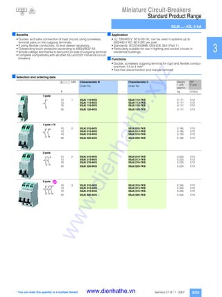
Standard Product Range
5SJ6 ...-.KS, 6 kA
3/26 Siemens ET B1 T · 2007
■Characteristic curves
Melting I2
t values
Characteristic B Characteristic C
■Dimensional drawings
10-1
10-1
100
101100 102
2
4
6
101
2
4
6
102
2
4
6
2 4 6 8 2 4 6 8 2 4 6 8
p
I2_13443
[kA]
2
[kAs]2
13/16/20 A
10 A
10-1
10-2
100
10010-1 101
2
4
6
10-2
2
4
6
101
2
4
6
102
2
4
6
2 4 6 8 2 4 6 8 2 4 6 8 1022 4 6 8
p
I2_13444
[kA]
2
[kAs]2
20 A
13/16 A
10 A
3618 54
2
44
70
6
45
90
I2_12855
62 4 2 4
1 51 3 1 3
www.dienhathe.xyz
www.dienhathe.vn](https://image.slidesharecdn.com/dienhathe-180716022044/85/Dienhathe-com-miniature-circuit-breakers-26-320.jpg)
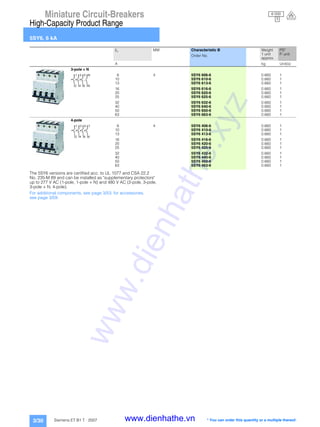
![Miniature Circuit-Breakers
High-Capacity Product Range
5SY6, 6 kA
3/33Siemens ET B1 T · 2007
1
2
3
4
5
6
7
8
9
10
11
12
13
14
15
16
17
■Characteristic curves
Melting I2
t values
Characteristic B
Characteristic C
Characteristic D
■Dimensional drawings
2 4 6 1 0
p [ k A ]
2
[kAs]
1 0
2
I2_10761
5 0 / 6 3 A
2 5 / 3 2 / 4 0 A
1 3 / 1 6 / 2 0 A
1 0 A
6 A
- 1 2 4 6 8 1 0 0 18 2 4 6 1 0 28
1 0 - 1
2
4
6
1 0 0
2
4
6
1 0 1
2
4
6
1 0 2
p [ k A ]
2
[kAs]2
I2_10762
5 0 / 6 3 A
1 3 / 1 6 A
2 0 / 2 5 / 3 2 / 4 0 A
8 / 1 0 A
6 A
3 / 4 A
2 A
0 , 5 A
0 , 3 A
1 A
1 , 6 A
2
4
6
1 0 - 1
2
4
6
1 0 0
2
4
6
1 0 1
2
4
6
1 0 2
2 4 6 1 01 0 - 2 2 4 6 8 1 0 - 1 2 4 6 8 1 0 0 18 2 4 6 1 0 28
1 0 - 2
p [ k A ]
2
[kAs]2
I2_10763
4 0 / 5 0 / 6 3 A
3 2 A
2 5 A
2 0 A
1 6 A
8 / 1 0 / 1 3 A
1 A
0 , 5 A
0 , 3 A
6 A
4 A
3 A
2 A
1 , 6 A
2 4 6 1 01 0 - 2 2 4 6 8 1 0 - 1 2 4 6 8 1 0 0 18 2 4 6 1 0 28
1 0 - 2
2
4
6
1 0 - 1
2
4
6
1 0 0
2
4
6
1 0 1
2
4
6
1 0 2
3618 54 44
70
6
45
90
I2_07796
72
1 1 3 1 3 5 1 3 5 7
2 2 4 2 4 6 2 4 6 8
www.dienhathe.xyz
www.dienhathe.vn](https://image.slidesharecdn.com/dienhathe-180716022044/85/Dienhathe-com-miniature-circuit-breakers-33-320.jpg)
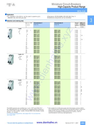
![Miniature Circuit-Breakers
High-Capacity Product Range
5SJ4 ...-.HG41, 14 kA
3/36 Siemens ET B1 T · 2007
■Characteristic curves
5SJ4 ...-.HG40, 5SJ4 ...-.HG41
Melting I2
t values
Characteristic B
Characteristic C
Characteristic D
■Dimensional drawings
5SJ4 ...-.HG41
I2_13382
50/60/63 A
10 A
6 A
10-1
10-2
2
4
6
100
2
4
6
101
2
4
6
102
2
4
6
103
2
4
6
[kA2s]
10-1 2 4 6 8 2 4 6 8 2 4 6 8100 101 102
p [kA]
13/15/16/20 A
25/30/32/35/40/45 A
t2
101
I2_13384
30/32/35 A
8/10/13 A
2 A
3 A
4 A
5/6 A
1,6 A
20 A
25 A
1 A
0,5 A
0,3 A
15/16 A
40/45/50/60/63 A
10-1
10-2
2
4
6
100
2
4
6
101
2
4
6
102
2
4
6
103
2
4
6
[kA2s]
10-2 10-12 4 6 8 2 4 6 8 2 4 6 8 2 4 6 8100 102
p [kA]
t2
101
I2_13384
30/32/35 A
8/10/13 A
2 A
3 A
4 A
5/6 A
1,6 A
20 A
25 A
1 A
0,5 A
0,3 A
15/16 A
40/45/50/60/63 A
10-1
10-2
2
4
6
100
2
4
6
101
2
4
6
102
2
4
6
103
2
4
6
[kA2s]
10-2 10-12 4 6 8 2 4 6 8 2 4 6 8 2 4 6 8100 102
p [kA]
t2
18 36 54
I2_12749
45
110
466,4
70
www.dienhathe.xyz
www.dienhathe.vn](https://image.slidesharecdn.com/dienhathe-180716022044/85/Dienhathe-com-miniature-circuit-breakers-36-320.jpg)
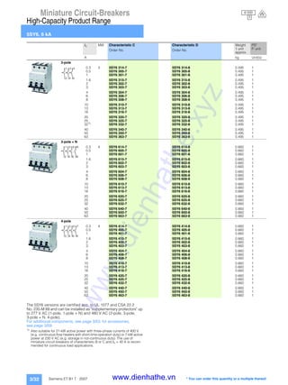
![Miniature Circuit-Breakers
High-Capacity Product Range
5SY4, 10 kA
3/41Siemens ET B1 T · 2007
1
2
3
4
5
6
7
8
9
10
11
12
13
14
15
16
17
■Characteristic curves
Melting I2
t values
Characteristic A
Characteristic B
Characteristic C
Characteristic D
2
p [ k A ]
2
[kAs]2
4 6 1 0
I2_10764
1 A
1 0
6 3 A
1 0 A
1 , 6 A
2 A
3 A
4 A
6 / 8 A
3 2 / 4 0 / 5 0 A
1 3 / 1 6 / 2 0 / 2 5 A
- 2 2 4 6 8 1 0 - 1 2 4 6 8 1 0 0 18 2 4 6 1 0 28
1 0 - 2
2
4
6
1 0 - 1
2
4
6
1 0 0
2
4
6
1 0 1
2
4
6
1 0 2
1 0 2 4 6 1 0
p
6
4
2
1 0
6
4
2
1 0
1 0
[ k A ]
2
[kAs]
1 0
2
1 0
I2_10765
5 0 / 6 3 A
6 A
2 5 / 3 2 / 4 0 A
1 3 / 1 6 / 2 0 A
1 0 A
- 1 2 4 6 8 0 8 1 2 4 6 8 2
- 1
1 0 0
1
6
4
2
2
p [ k A ]
2
[kAs]2
I2_10766
5 0 / 6 3 A
1 A
2 0 / 2 5 / 3 2 / 4 0 A
1 3 / 1 6 A
8 / 1 0 A
6 A
3 / 4 A
2 A
1 , 6 A
0 , 5 A
0 , 3 A
2
4
6
1 0 - 2
1 0 - 1
1 0 0
1 0 1
1 0 2
2
4
6
2
4
6
2
4
6
2 4 6 1 0 1 01 0 2 4 6 8 1 0 - 1
2 4 6 8 1 0 0 1
8 2 4 6 8 2- 2
2
p [ k A ]
2
[kAs]2
4 6 1 0 1 0
2
4
6
I2_10767
1 0 2 4 6
4 0 / 5 0 / 6 3 A
2 5 A
8 / 1 0 / 1 3 A
6 A
4 A
3 A
1 , 6 A
0 , 5 A
0 , 3 A
2 0 A
1 6 A
2 A
1 A
3 2 A
- 2
8 1 0 - 1
2 4 6 8 1 0 0 1
8 2 4 6 8 2
1 0 - 2
1 0 - 1
1 0 0
1 0 1
1 0 2
1 0 3
2
4
6
2
4
6
2
4
6
2
4
6
www.dienhathe.xyz
www.dienhathe.vn](https://image.slidesharecdn.com/dienhathe-180716022044/85/Dienhathe-com-miniature-circuit-breakers-41-320.jpg)
![Miniature Circuit-Breakers
High-Capacity Product Range
5SY7, 15 kA
3/46 Siemens ET B1 T · 2007
■Characteristic curves
Melting I2
t values
Characteristic B
Characteristic C
Characteristic D
■Dimensional drawings
p
2
[ k A ]
2
[kAs]2
I2_10768
5 0 / 6 3 A 2 5 / 3 2 / 4 0 A
1 0 A
6 A
1 3 / 1 6 / 2 0 A
1 0 2 4 6 1 0
1 0
1 0 1 0- 1 2 4 6 8 0 8 1 2 4 6 8 2
- 1
4
6
2
1 0 0
4
6
2
1 0 1
4
6
1 0 2
p [ k A ]
2
[kAs]2
2
I2_10769
2 A
3 / 4 A
6 A
2 0 / 2 5 / 3 2 / 4 0 A
1 A
1 , 6 A
0 , 5 A
0 , 3 A
8 / 1 0 A
1 3 / 1 6 A
5 0 / 6 3 A
2 6 1 01 0 4- 2 2 64 1 0 - 18 2 64 1 0 08 18 2 6 1 04 28
1 0 - 2
4
6
2
1 0 - 1
4
6
2
1 0 0
4
6
2
1 0 1
4
6
1 0 2
p [ k A ]
2
[kAs]2
I2_10770
1 6 A
2 0 A
0 , 3 A
2 5 A
3 2 A
4 0 / 5 0 / 6 3 A
8 / 1 0 / 1 3 A
6 A
1 , 6 A
0 , 5 A
3 A
1 A
4 A
2 A
2 6 1 01 0 4- 2 2 64 1 0 - 18 2 64 1 0 08 18 2 6 1 04 28
1 0 - 2
2
4
6
1 0
2
4
6
- 1
1 0
2
4
6
0
1 0
2
4
6
1
1 0
2
4
6
2
1 0 3
3618 54 44
70
6
45
90
I2_07796
72
1 1 3 1 3 5 1 3 5 7
2 2 4 2 4 6 2 4 6 8
www.dienhathe.xyz
www.dienhathe.vn](https://image.slidesharecdn.com/dienhathe-180716022044/85/Dienhathe-com-miniature-circuit-breakers-46-320.jpg)
![Miniature Circuit-Breakers
High-Capacity Product Range
5SY8, 25 kA
3/49Siemens ET B1 T · 2007
1
2
3
4
5
6
7
8
9
10
11
12
13
14
15
16
17
■Characteristic curves
Melting I2
t values
Characteristic C Characteristic D
■Dimensional drawings
2
p [ k A ]
2
[kAs]2
6 1 0
I2_10771
1 0 4
0 , 3 A
1 3 / 1 6 A
2 0 / 2 5 / 3 2 A
5 0 / 6 3 A
8 / 1 0 A
6 A
1 , 6 A
0 , 5 A
1 A
3 / 4 A
2 A
4 0 A
- 2 2 64 1 0 - 18 2 64 1 0 08 18 2 6 1 04 28 2 6 1 04 38
1 0 - 2
2
4
6
1 0 - 1
2
4
6
1 0 0
2
4
6
1 0 1
2
4
6
1 0 2
2
4
6
1 0 3
I2_10772
p [ k A ]
2
[kAs]2
0 , 5 A
0 , 3 A
5 0 / 6 3 A
8 / 1 0 A
2 0 A
1 3 / 1 6 A
2 5 A
3 2 A
4 0 A
2 A
6 A
4 A
3 A
1 A
1 , 6 A
2 6 1 01 0 4- 2 2 64 1 0 - 18 2 64 1 0 08 18 2 6 1 04 28 2 6 1 04 38
1 0 - 2
2
4
6
1 0 - 1
2
4
6
1 0 0
2
4
6
1 0 1
2
4
6
1 0 2
2
4
6
1 0 3
3618 54 44
70
6
45
90
I2_07796
72
1 1 3 1 3 5 1 3 5 7
2 2 4 2 4 6 2 4 6 8
www.dienhathe.xyz
www.dienhathe.vn](https://image.slidesharecdn.com/dienhathe-180716022044/85/Dienhathe-com-miniature-circuit-breakers-49-320.jpg)
![Miniature Circuit-Breakers
UC Product Range
5SY5, 10 kA
3/51Siemens ET B1 T · 2007
1
2
3
4
5
6
7
8
9
10
11
12
13
14
15
16
17
■Characteristic curves
Melting I2
t values
Characteristic B Characteristic C
■Dimensional drawings
2 4 6 1 0
p [ k A ]
2
[kAs]
1 0
2
I2_10773
6 A
5 0 / 6 3 A
2 5 A
3 2 / 4 0 A
1 3 / 1 6 A
1 0 A
- 1 2 4 6 8 1 0 0 8 1 2 4 6 1 08 2
1 0 - 2
2
4
6
1 0 - 1
2
4
6
1 0 0
2
4
6
1 0 1
2
4
6
1 0 2
p [ k A ]
2
[kAs]2
I2_10774
2 A
3 / 4 A
1 , 6 A
1 A
0 , 5 A
0 , 3 A
2 4 6 1 01 0 - 1 2 4 6 8 1 0 0 8 1 2 4 6 1 08 2
1 0 - 2
2
4
6
1 0 - 1
2
4
6
1 0 0
2
4
6
1 0 1
2
4
6
1 0 2
1 0 A
8 A
6 A
6 3 A
5 0 A
4 0 A
2 5 / 3 2 A
1 3 / 1 6 A
3618 54 44
70
6
45
90
I2_07796
72
1 1 3 1 3 5 1 3 5 7
2 2 4 2 4 6 2 4 6 8
www.dienhathe.xyz
www.dienhathe.vn](https://image.slidesharecdn.com/dienhathe-180716022044/85/Dienhathe-com-miniature-circuit-breakers-51-320.jpg)

This document provides an overview of Siemens miniature circuit breakers, including their standard, high-capacity, universal current, high current, and power supply company product ranges. It describes the benefits of the circuit breakers, such as their high rated breaking capacity, excellent current limitation, and individually mountable additional components. Technical specifications are provided for the different product lines, including their tripping characteristics, voltages, terminals, and environmental resistance.


