Download to read offline
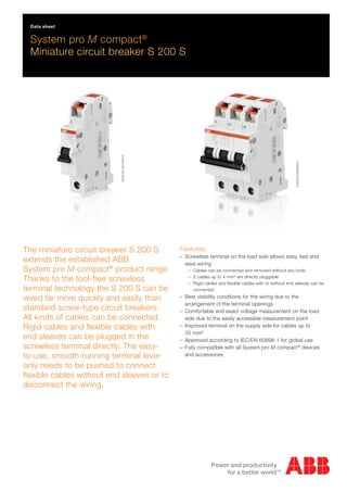
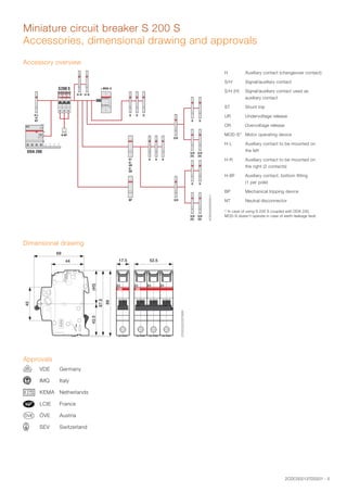
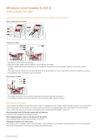
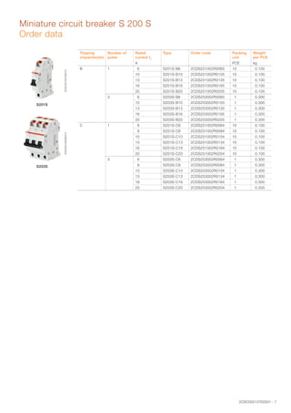
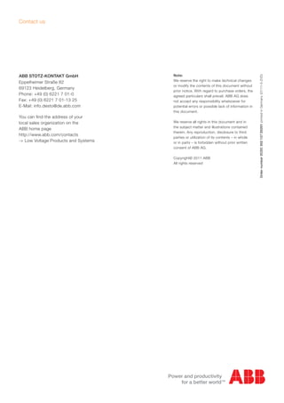

The document provides information on the S 200 S miniature circuit breaker from ABB. It has a screwless terminal that allows for quick and easy wiring without tools. Various cable types can be directly connected to the terminal. The breaker extends ABB's System pro M compact product range and offers faster installation than standard screw-type breakers. It provides overcurrent and short circuit protection for circuits up to 20A.


