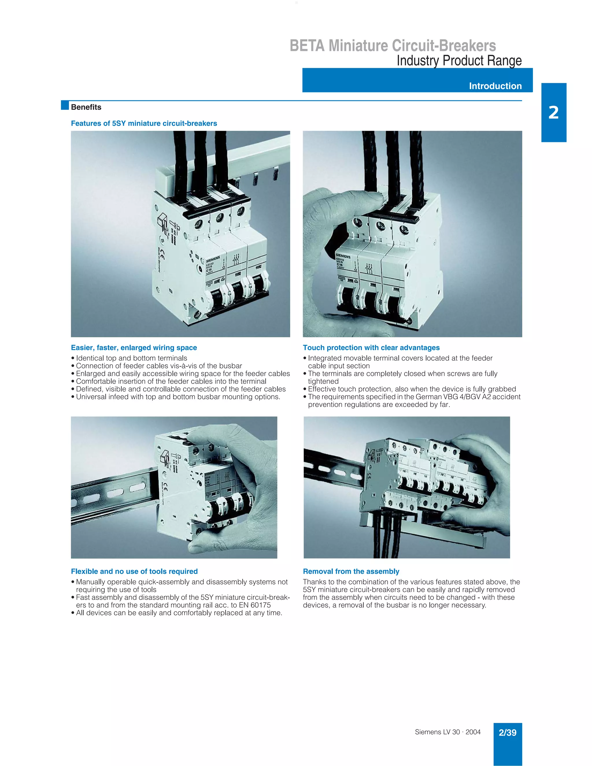
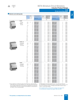
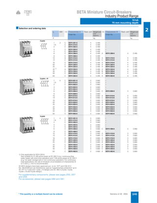
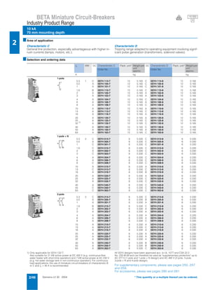
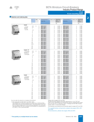
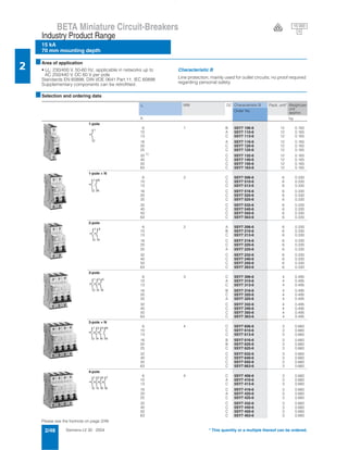
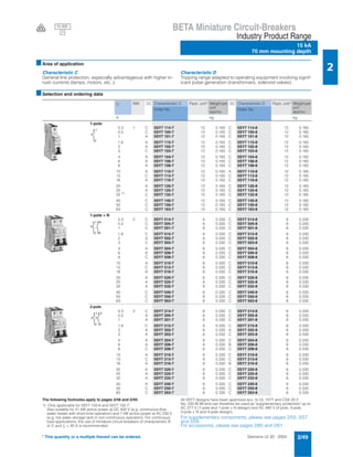
The document provides information on Siemens 5SY miniature circuit-breakers, including:
- The circuit-breakers offer easier wiring installation with identical top and bottom terminals and enlarged wiring space. They also provide touch protection when terminals are fully tightened.
- Circuit-breakers can be manually assembled and disassembled without tools, allowing for fast replacement.
- Characteristics B and C are described for line protection applications with C handling higher inrush currents. Characteristic D has a tripping range for equipment with pulse loads.
- Selection and ordering data is given for 1-pole through 4-pole circuit-breakers ranging from 0.3A to 63A in characteristics B, C
Siemens,
Catalog Thiết Bị Điện Siemens, Catalog Thiết Bị Điện,
Catalog Phụ Kiện Siemens, Catalog Phụ Kiện,
Catalog Siemens, Catalog,
http://dienhathe.com,
Chi tiết các sản phẩm khác của Siemens tại https://dienhathe.com
Xem thêm các Catalog khác của Siemens tại https://dienhathe.info
Để nhận báo giá sản phẩm Siemens vui lòng gọi: 0907.764.966
ABB Contactors - 4 Pole Contactors ABB AF09 AF09Z (AC DC) Contactors
ABB Extended Product Type:
ABB AF09-40-00-11
ABB Product ID:
1SBL137201R1100
EAN: 3471523115019
ABB Catalogue Description:
ABB 4 Pole Contactors : AF09-40-00-11 24-60V50/60HZ 20-60VDC Contactor
ABB AF09 4-pole contactors are used for controlling power circuits up to 690 V AC and 440 V DC. ABB AF09 contactors are mainly used for controlling non-inductive or slightly inductive loads (i.e. resistance furnaces...). ABB AF09 contactors include an electronic coil interface accepting a wide control voltage Uc min. ... Uc max. Only four coils cover control voltages between 24...500 V 50/60 Hz or 20...500 V DC. ABB AF contactors can manage large control voltage variations. One coil can be used for different control voltages used worldwide without any coil change. ABB AF contactors have built-in surge protection and do not require additional surge suppressors. The ABB AF... series 4-pole contactors are of the block type design. Main poles and auxiliary contact blocks: 4 N.O. main poles, front and side-mounted add-on auxiliary contact blocks (mechanically-linked auxiliary contacts compliant with Annex L of IEC 60947-5-1. N.C. mirror contacts compliant with Annex F of IEC 60947-4-1) - Control circuit: AC or DC operated - Accessories: a wide range of accessories is available. Note: - AF..-..-..-11 not suitable for a direct control by PLC-output. - ABB AF..-..-..-11 type available in some countries: please consult Thorne & Derrick t 00 44 191 4901547
Cataloge ge 2.industrial components_dienhathe.com-1_record_plusDien Ha The
Khoa Học - Kỹ Thuật & Giải Trí: http://phongvan.org
Tài Liệu Khoa Học Kỹ Thuật: http://tailieukythuat.info
Thiết bị Điện Công Nghiệp - Điện Hạ Thế: http://dienhathe.vn
The Ashcroft® NPI indicating pressure switch was designed to satisfy challenging applications needing high cycle rates with switch functionality. The Ashcroft® NPA watertight pressure switch was designed to satisfy challenging applications needing high cycle rates with switch functionality
Catalog đèn báo nút nhấn công tắc IDEC (Nhật Bản) - dòng TWCTY TNHH HẠO PHƯƠNG
Công ty Cổ phần Hạo Phương xin gửi đến quý khách hàng Catalog về đèn báo, nút nhấn, công tắc xoay Idec (Nhật Bản) phi 22 dòng TW. Catalog chứa đầy đủ thông tin về sản phẩm, kích thước và những lưu ý để sử dụng thiết bị hiệu quả.
Điểm đặc biệt của đèn báo IDEC phi 22 là có thể dễ dàng chuyển đổi từ phi 22 sang phi 25, điều mà hiếm có sản phẩm nào trên thị trường có thể làm được.
Catalog thiết bị điện MCB BC E Series Fuji, MCB BC E Series Fuji,
Beeteco.com là trang mua sắm trực tuyến thiết bị điện - Tự động hóa uy tín tại Việt Nam.
Chuyên cung cấp các thiết bị: Đèn báo nút nhấn, Relay, Timer, Contactor, MCCB ELCB, Biến tần, Van, Thiết bị cảm biến, phụ kiện tủ điện, .... Từ các thương hiệu hàng đầu trên thế giới.
www.beeteco.com @ Công ty TNHH TM KT ASTER
Địa chỉ : Số 7/31 KDC Thương Mại Sóng Thần, KP. Nhị Đồng 1, P. Dĩ An, Tx. Dĩ An, Tỉnh Bình Dương
FB: www.facebook.com/beeteco
Email: contact@beeteco.com
Tel: 0650 3617 012
Hotline: 0909.41.61.43
PT. Siwali Swantika merupakan distributor resmi Fluke di Indonesia. Selain penjualan alat ukur Fluke, perusahaan kami juga menyediakan jasa kalibrasi dan jasa perbaikan untuk alat ukur Fluke. Informasi lebih detail hubungi PT. Siwali Swantika, Jakarta Office : 021-45850618 atau Surabaya Office : 031-8421264
Catalog Actuator Damper HoneyWell ( Động cơ điều khiển van gió)Beeteco
Beeteco.com là trang mua sắm trực tuyến thiết bị điện - Tự động hóa uy tín tại Việt Nam.
Chuyên cung cấp các thiết bị: Đèn báo nút nhấn, Relay, Timer, Contactor, MCCB ELCB, Biến tần, Van, Thiết bị cảm biến, phụ kiện tủ điện, .... Từ các thương hiệu hàng đầu trên thế giới.
www.beeteco.com @ Công ty TNHH TM KT ASTER
Số 7 Đại Lộ Độc Lập, KCN Sóng Thần 1, P. Dĩ An, Tx. Dĩ An, Bình Dương
Dienhathe.com miniature circuit breakersDien Ha The
Siemens,
Catalog Thiết Bị Điện Siemens, Catalog Thiết Bị Điện,
Catalog Phụ Kiện Siemens, Catalog Phụ Kiện,
Catalog Siemens, Catalog,
http://dienhathe.com,
Chi tiết các sản phẩm khác của Siemens tại https://dienhathe.com
Xem thêm các Catalog khác của Siemens tại https://dienhathe.info
Để nhận báo giá sản phẩm Siemens vui lòng gọi: 0907.764.966
Catalog cs switch disconnector_fuse_units_dienhathe.vnDien Ha The
Khoa Học - Kỹ Thuật & Giải Trí: http://phongvan.org
Tài Liệu Khoa Học Kỹ Thuật: http://tailieukythuat.info
Thiết bị Điện Công Nghiệp - Điện Hạ Thế: http://dienhathe.vn
Catalog cs switch disconnector_fuse_unitsDien Ha The
Catalog cs switch disconnector_fuse_units
Catalog CS,
Catalog Thiết Bị Điện CS,
Catalog Điện Công Nghiệp CS,
http://dienhathe.com,
Xem thêm các sản phẩm khác của CS tại https://dienhathe.com
Để nhận báo giá sản phẩm CS vui lòng gọi: 0907.764.966
Catalog cs switch disconnector_fuse_units
C&S,
Catalog C&S,
Catalog Thiết Bị Điện C&S,
Catalog Điện Công Nghiệp C&S,
http://dienhathe.com,
Xem thêm các sản phẩm khác của Autonics tại https://dienhathe.com
Để nhận báo giá sản phẩm vui lòng gọi: 0907.764.966
Siemens,
Catalog Thiết Bị Điện Siemens, Catalog Thiết Bị Điện,
Catalog Phụ Kiện Siemens, Catalog Phụ Kiện,
Catalog Siemens, Catalog,
http://dienhathe.com,
Chi tiết các sản phẩm khác của Siemens tại https://dienhathe.com
Xem thêm các Catalog khác của Siemens tại https://dienhathe.info
Để nhận báo giá sản phẩm Siemens vui lòng gọi: 0907.764.966
MCB Fuji: thiết bị đóng cắt Fuji
Beeteco.com là trang mua sắm trực tuyến thiết bị điện - Tự động hóa uy tín tại Việt Nam.
Chuyên cung cấp các thiết bị: Đèn báo nút nhấn, Relay, Timer, Contactor, MCCB ELCB, Biến tần, Van, Thiết bị cảm biến, phụ kiện tủ điện, .... Từ các thương hiệu hàng đầu trên thế giới.
www.beeteco.com @ Công ty TNHH TM KT ASTER
Số 7 Đại Lộ Độc Lập, KCN Sóng Thần 1, P. Dĩ An, Tx. Dĩ An, Bình Dương
www.facebook.com/beeteco
Tel: 0650 3617 012
DĐ: 0904 676 925
Lawson Fuses - power safe solutions
BSI, IEC & CENELEC Standard Fuses
Lawson low voltage fuses provide reliable circuit protection : general purpose fuses, industrial fuses, IEC fuses, street lighting fuses, motor circuit fuses, compact dimension fuses, utility fuses and DIN standard fuses.
Lawson Fuses - Ranges Available :
Industrial Fuse Links - Lawson industrial fuse link range complies with the dimensional requirements and current ratings of BS88 : Part 2 and IEC60269-2. 400/415V and 660/690V a.c. industrial fuses are available.
Compact Dimension Fuse Links - Lawson compact dimension fuse links with offset blade tags meet the requirements of BS88 : Part 6 and IEC60269-2 at rated voltages 230/240V and 400/415V a.c.
Motor Circuit Fuse Links - Lawson motor circuit fuse links accomodate the starting current of motors providing reliable circuit protection.
Utility Fuse Links - Lawson utility fuse links for electricity supply networks comply with BS88 : Part 5.
Semi Conductor Fuse Links - Lawson high speed fuse links for the protection of semi-conductor devices (240V and 690V) comply with the performance and dimensional requirements of BS88.
DIN Specification Fuse Links - Lawson 500V NH fuse links are manufactured in accordance with DIN 43 620.
Idec catalog switching power supplies ep1196 0ps5r-sallslimDien Ha The
Idec catalog switching power supplies ep1196 0ps5r-sallslim
Catalog Idec, Catalog,
Catalog Thiết Bị Điện Idec, Catalog Thiết Bị Điện,
Catalog Điện Công Nghiệp Idec, Catalog Điện Công Nghiệp,
http://dienhathe.com,
Chi tiết các sản phẩm khác của Idec tại https://dienhathe.com
Xem thêm các Catalog khác của Idec tại https://dienhathe.info
Để nhận báo giá sản phẩm Idec vui lòng gọi: 0907.764.966
Title: Sense of Smell
Presenter: Dr. Faiza, Assistant Professor of Physiology
Qualifications:
MBBS (Best Graduate, AIMC Lahore)
FCPS Physiology
ICMT, CHPE, DHPE (STMU)
MPH (GC University, Faisalabad)
MBA (Virtual University of Pakistan)
Learning Objectives:
Describe the primary categories of smells and the concept of odor blindness.
Explain the structure and location of the olfactory membrane and mucosa, including the types and roles of cells involved in olfaction.
Describe the pathway and mechanisms of olfactory signal transmission from the olfactory receptors to the brain.
Illustrate the biochemical cascade triggered by odorant binding to olfactory receptors, including the role of G-proteins and second messengers in generating an action potential.
Identify different types of olfactory disorders such as anosmia, hyposmia, hyperosmia, and dysosmia, including their potential causes.
Key Topics:
Olfactory Genes:
3% of the human genome accounts for olfactory genes.
400 genes for odorant receptors.
Olfactory Membrane:
Located in the superior part of the nasal cavity.
Medially: Folds downward along the superior septum.
Laterally: Folds over the superior turbinate and upper surface of the middle turbinate.
Total surface area: 5-10 square centimeters.
Olfactory Mucosa:
Olfactory Cells: Bipolar nerve cells derived from the CNS (100 million), with 4-25 olfactory cilia per cell.
Sustentacular Cells: Produce mucus and maintain ionic and molecular environment.
Basal Cells: Replace worn-out olfactory cells with an average lifespan of 1-2 months.
Bowman’s Gland: Secretes mucus.
Stimulation of Olfactory Cells:
Odorant dissolves in mucus and attaches to receptors on olfactory cilia.
Involves a cascade effect through G-proteins and second messengers, leading to depolarization and action potential generation in the olfactory nerve.
Quality of a Good Odorant:
Small (3-20 Carbon atoms), volatile, water-soluble, and lipid-soluble.
Facilitated by odorant-binding proteins in mucus.
Membrane Potential and Action Potential:
Resting membrane potential: -55mV.
Action potential frequency in the olfactory nerve increases with odorant strength.
Adaptation Towards the Sense of Smell:
Rapid adaptation within the first second, with further slow adaptation.
Psychological adaptation greater than receptor adaptation, involving feedback inhibition from the central nervous system.
Primary Sensations of Smell:
Camphoraceous, Musky, Floral, Pepperminty, Ethereal, Pungent, Putrid.
Odor Detection Threshold:
Examples: Hydrogen sulfide (0.0005 ppm), Methyl-mercaptan (0.002 ppm).
Some toxic substances are odorless at lethal concentrations.
Characteristics of Smell:
Odor blindness for single substances due to lack of appropriate receptor protein.
Behavioral and emotional influences of smell.
Transmission of Olfactory Signals:
From olfactory cells to glomeruli in the olfactory bulb, involving lateral inhibition.
Primitive, less old, and new olfactory systems with different path
Adv. biopharm. APPLICATION OF PHARMACOKINETICS : TARGETED DRUG DELIVERY SYSTEMSAkankshaAshtankar
MIP 201T & MPH 202T
ADVANCED BIOPHARMACEUTICS & PHARMACOKINETICS : UNIT 5
APPLICATION OF PHARMACOKINETICS : TARGETED DRUG DELIVERY SYSTEMS By - AKANKSHA ASHTANKAR
CDSCO and Phamacovigilance {Regulatory body in India}NEHA GUPTA
The Central Drugs Standard Control Organization (CDSCO) is India's national regulatory body for pharmaceuticals and medical devices. Operating under the Directorate General of Health Services, Ministry of Health & Family Welfare, Government of India, the CDSCO is responsible for approving new drugs, conducting clinical trials, setting standards for drugs, controlling the quality of imported drugs, and coordinating the activities of State Drug Control Organizations by providing expert advice.
Pharmacovigilance, on the other hand, is the science and activities related to the detection, assessment, understanding, and prevention of adverse effects or any other drug-related problems. The primary aim of pharmacovigilance is to ensure the safety and efficacy of medicines, thereby protecting public health.
In India, pharmacovigilance activities are monitored by the Pharmacovigilance Programme of India (PvPI), which works closely with CDSCO to collect, analyze, and act upon data regarding adverse drug reactions (ADRs). Together, they play a critical role in ensuring that the benefits of drugs outweigh their risks, maintaining high standards of patient safety, and promoting the rational use of medicines.
Recomendações da OMS sobre cuidados maternos e neonatais para uma experiência pós-natal positiva.
Em consonância com os ODS – Objetivos do Desenvolvimento Sustentável e a Estratégia Global para a Saúde das Mulheres, Crianças e Adolescentes, e aplicando uma abordagem baseada nos direitos humanos, os esforços de cuidados pós-natais devem expandir-se para além da cobertura e da simples sobrevivência, de modo a incluir cuidados de qualidade.
Estas diretrizes visam melhorar a qualidade dos cuidados pós-natais essenciais e de rotina prestados às mulheres e aos recém-nascidos, com o objetivo final de melhorar a saúde e o bem-estar materno e neonatal.
Uma “experiência pós-natal positiva” é um resultado importante para todas as mulheres que dão à luz e para os seus recém-nascidos, estabelecendo as bases para a melhoria da saúde e do bem-estar a curto e longo prazo. Uma experiência pós-natal positiva é definida como aquela em que as mulheres, pessoas que gestam, os recém-nascidos, os casais, os pais, os cuidadores e as famílias recebem informação consistente, garantia e apoio de profissionais de saúde motivados; e onde um sistema de saúde flexível e com recursos reconheça as necessidades das mulheres e dos bebês e respeite o seu contexto cultural.
Estas diretrizes consolidadas apresentam algumas recomendações novas e já bem fundamentadas sobre cuidados pós-natais de rotina para mulheres e neonatos que recebem cuidados no pós-parto em unidades de saúde ou na comunidade, independentemente dos recursos disponíveis.
É fornecido um conjunto abrangente de recomendações para cuidados durante o período puerperal, com ênfase nos cuidados essenciais que todas as mulheres e recém-nascidos devem receber, e com a devida atenção à qualidade dos cuidados; isto é, a entrega e a experiência do cuidado recebido. Estas diretrizes atualizam e ampliam as recomendações da OMS de 2014 sobre cuidados pós-natais da mãe e do recém-nascido e complementam as atuais diretrizes da OMS sobre a gestão de complicações pós-natais.
O estabelecimento da amamentação e o manejo das principais intercorrências é contemplada.
Recomendamos muito.
Vamos discutir essas recomendações no nosso curso de pós-graduação em Aleitamento no Instituto Ciclos.
Esta publicação só está disponível em inglês até o momento.
Prof. Marcus Renato de Carvalho
www.agostodourado.com
TEST BANK for Operations Management, 14th Edition by William J. Stevenson, Ve...kevinkariuki227
TEST BANK for Operations Management, 14th Edition by William J. Stevenson, Verified Chapters 1 - 19, Complete Newest Version.pdf
These simplified slides by Dr. Sidra Arshad present an overview of the non-respiratory functions of the respiratory tract.
Learning objectives:
1. Enlist the non-respiratory functions of the respiratory tract
2. Briefly explain how these functions are carried out
3. Discuss the significance of dead space
4. Differentiate between minute ventilation and alveolar ventilation
5. Describe the cough and sneeze reflexes
Study Resources:
1. Chapter 39, Guyton and Hall Textbook of Medical Physiology, 14th edition
2. Chapter 34, Ganong’s Review of Medical Physiology, 26th edition
3. Chapter 17, Human Physiology by Lauralee Sherwood, 9th edition
4. Non-respiratory functions of the lungs https://academic.oup.com/bjaed/article/13/3/98/278874
Basavarajeeyam is a Sreshta Sangraha grantha (Compiled book ), written by Neelkanta kotturu Basavaraja Virachita. It contains 25 Prakaranas, First 24 Chapters related to Rogas& 25th to Rasadravyas.
Title: Sense of Taste
Presenter: Dr. Faiza, Assistant Professor of Physiology
Qualifications:
MBBS (Best Graduate, AIMC Lahore)
FCPS Physiology
ICMT, CHPE, DHPE (STMU)
MPH (GC University, Faisalabad)
MBA (Virtual University of Pakistan)
Learning Objectives:
Describe the structure and function of taste buds.
Describe the relationship between the taste threshold and taste index of common substances.
Explain the chemical basis and signal transduction of taste perception for each type of primary taste sensation.
Recognize different abnormalities of taste perception and their causes.
Key Topics:
Significance of Taste Sensation:
Differentiation between pleasant and harmful food
Influence on behavior
Selection of food based on metabolic needs
Receptors of Taste:
Taste buds on the tongue
Influence of sense of smell, texture of food, and pain stimulation (e.g., by pepper)
Primary and Secondary Taste Sensations:
Primary taste sensations: Sweet, Sour, Salty, Bitter, Umami
Chemical basis and signal transduction mechanisms for each taste
Taste Threshold and Index:
Taste threshold values for Sweet (sucrose), Salty (NaCl), Sour (HCl), and Bitter (Quinine)
Taste index relationship: Inversely proportional to taste threshold
Taste Blindness:
Inability to taste certain substances, particularly thiourea compounds
Example: Phenylthiocarbamide
Structure and Function of Taste Buds:
Composition: Epithelial cells, Sustentacular/Supporting cells, Taste cells, Basal cells
Features: Taste pores, Taste hairs/microvilli, and Taste nerve fibers
Location of Taste Buds:
Found in papillae of the tongue (Fungiform, Circumvallate, Foliate)
Also present on the palate, tonsillar pillars, epiglottis, and proximal esophagus
Mechanism of Taste Stimulation:
Interaction of taste substances with receptors on microvilli
Signal transduction pathways for Umami, Sweet, Bitter, Sour, and Salty tastes
Taste Sensitivity and Adaptation:
Decrease in sensitivity with age
Rapid adaptation of taste sensation
Role of Saliva in Taste:
Dissolution of tastants to reach receptors
Washing away the stimulus
Taste Preferences and Aversions:
Mechanisms behind taste preference and aversion
Influence of receptors and neural pathways
Impact of Sensory Nerve Damage:
Degeneration of taste buds if the sensory nerve fiber is cut
Abnormalities of Taste Detection:
Conditions: Ageusia, Hypogeusia, Dysgeusia (parageusia)
Causes: Nerve damage, neurological disorders, infections, poor oral hygiene, adverse drug effects, deficiencies, aging, tobacco use, altered neurotransmitter levels
Neurotransmitters and Taste Threshold:
Effects of serotonin (5-HT) and norepinephrine (NE) on taste sensitivity
Supertasters:
25% of the population with heightened sensitivity to taste, especially bitterness
Increased number of fungiform papillae
ARTIFICIAL INTELLIGENCE IN HEALTHCARE.pdfAnujkumaranit
Artificial intelligence (AI) refers to the simulation of human intelligence processes by machines, especially computer systems. It encompasses tasks such as learning, reasoning, problem-solving, perception, and language understanding. AI technologies are revolutionizing various fields, from healthcare to finance, by enabling machines to perform tasks that typically require human intelligence.
The Gram stain is a fundamental technique in microbiology used to classify bacteria based on their cell wall structure. It provides a quick and simple method to distinguish between Gram-positive and Gram-negative bacteria, which have different susceptibilities to antibiotics
1. Siemens LV 30 · 2004 2/39
BETA Miniature Circuit-Breakers
Industry Product Range
Introduction
2
* This quantity or a multiple thereof can be ordered.
■Benefits
Features of 5SY miniature circuit-breakers
Easier, faster, enlarged wiring space
• Identical top and bottom terminals
• Connection of feeder cables vis-à-vis of the busbar
• Enlarged and easily accessible wiring space for the feeder cables
• Comfortable insertion of the feeder cables into the terminal
• Defined, visible and controllable connection of the feeder cables
• Universal infeed with top and bottom busbar mounting options.
Touch protection with clear advantages
• Integrated movable terminal covers located at the feeder
cable input section
• The terminals are completely closed when screws are fully
tightened
• Effective touch protection, also when the device is fully grabbed
• The requirements specified in the German VBG 4/BGV A2 accident
prevention regulations are exceeded by far.
Flexible and no use of tools required
• Manually operable quick-assembly and disassembly systems not
requiring the use of tools
• Fast assembly and disassembly of the 5SY miniature circuit-break-
ers to and from the standard mounting rail acc. to EN 60175
• All devices can be easily and comfortably replaced at any time.
Removal from the assembly
Thanks to the combination of the various features stated above, the
5SY miniature circuit-breakers can be easily and rapidly removed
from the assembly when circuits need to be changed - with these
devices, a removal of the busbar is no longer necessary.
2. Siemens LV 30 · 20042/40
BETA Miniature Circuit-Breakers
6 kA
70 mm mounting depth
Industry Product Range
2
* This quantity or a multiple thereof can be ordered.
■Area of application
• Un: AC 230 V, 50-60 Hz
• Standards: EN 60898, DIN VDE 0641 Part 11, IEC 60898
Characteristic B
Line protection, mainly used for outlet circuits; no proof required
regarding personal safety.
Characteristic C
General line protection, especially advantageous with higher in-
rush currents (lamps, motors, etc.).
■Selection and ordering data
■Benefits
Auxiliary switch (AS)
• Can be retrofitted individually
• Mounting with factory-installed clips
• max. contact loading acc. to DIN VDE 0660 Part 200,
EN 60947-5-1:
6 A, AC 230 V, AC-15
1 A, DC 220 V, DC-13
• Short-circuit protection ensured by circuit-breakers with
characteristic B or C with In = 6 A or fuse gL 6 A
• Conductor cross-section 0.5 to 2.5 mm2
■Functions
• Remote indication of the miniature circuit-breaker’s switching
state: AS: ON/OFF
• Connectable to instabus EIB and AS-Interface bus via binary
inputs.
■Selection and ordering data
In MW DC Characteristic B Pack. unit* Weight per
unit
approx.
DC Characteristic C Pack. unit* Weight per
unit
approx.
Order No. Order No.
A kg kg
1-pole + N
2 1 - A 5SY6 002-7KV 12 0.132
4 - A 5SY6 004-7KV 12 0.132
6 A 5SY6 006-6KV 12 0.132 A 5SY6 006-7KV 12 0.132
8 - A 5SY6 008-7KV 12 0.132
10 A 5SY6 010-6KV 12 0.132 A 5SY6 010-7KV 12 0.132
13 A 5SY6 013-6KV 12 0.132 A 5SY6 013-7KV 12 0.132
16 A 5SY6 016-6KV 12 0.132 A 5SY6 016-7KV 12 0.132
20 A 5SY6 020-6KV 12 0.132 A 5SY6 020-7KV 12 0.132
25 A 5SY6 025-6KV 12 0.132 A 5SY6 025-7KV 12 0.132
32 A 5SY6 032-6KV 12 0.132 A 5SY6 032-7KV 12 0.132
40 A 5SY6 040-6KV 12 0.132 A 5SY6 040-7KV 12 0.132
2
1
N
N
I2_08258
instabus EIB
input
MCBAS
MW DC Order No. Pack.
unit*
Weight per
unit
approx.
kg
Auxiliary switch (AS) 1 NO + 1 NC 0.5 A 5ST3 018-0KV 1 0.037
13
12
21
22
3. Siemens LV 30 · 2004 2/41
BETA Miniature Circuit-Breakers
Industry Product Range
6 kA
70 mm mounting depth
2
* This quantity or a multiple thereof can be ordered.
■Area of application
• Un: 230/400 V, 50-60 Hz, applicable in networks up to
AC 250/440 V, DC 60 V per pole
• Standards EN 60898, DIN VDE 0641 Part 11, IEC 60898
• Supplementary components can be retrofitted.
Characteristic B
Line protection, mainly used for outlet circuits; no proof required
regarding personal safety.
■Selection and ordering data
1) Also suitable for 21 kW active power at DC 400 V (e.g. continuous-flow
water heater with short-time operation) and 7 kW active power at AC 230 V
(e.g. hot water storage tank in non-continuous operation). For continuous
load applications, the use of miniature circuit-breakers of characteristic B
or C and In = 40 A is recommended.
All 5SY6 designs have been approved acc. to UL 1077 and CSA 22.2
No. 235-M 89 and can therefore be used as "supplementary protectors" up to
AC 277 V (1-pole and 1-pole + N design) and AC 480 V (2-pole, 3-pole,
3-pole + N and 4-pole design).
For supplementary components, please see page 2/57.
For accessories, please see pages 2/60 and 2/61.
In MW DC Characteristic B Pack. unit* Weight per
unit
approx.Order No.
A kg
1-pole 6 1 A 5SY6 106-6 12 0.165
10 A 5SY6 110-6 12 0.165
13 A 5SY6 113-6 12 0.165
16 A 5SY6 116-6 12 0.165
20 B 5SY6 120-6 12 0.165
25 A 5SY6 125-6 12 0.165
321) A 5SY6 132-6 12 0.165
40 A 5SY6 140-6 12 0.165
50 A 5SY6 150-6 12 0.165
63 A 5SY6 163-6 12 0.165
1-pole + N 6 2 A 5SY6 506-6 6 0.330
10 A 5SY6 510-6 6 0.330
13 B 5SY6 513-6 6 0.330
16 A 5SY6 516-6 6 0.330
20 A 5SY6 520-6 6 0.330
25 A 5SY6 525-6 6 0.330
32 B 5SY6 532-6 6 0.330
40 B 5SY6 540-6 6 0.330
50 B 5SY6 550-6 6 0.330
63 B 5SY6 563-6 6 0.330
2-pole 6 2 A 5SY6 206-6 6 0.330
10 A 5SY6 210-6 6 0.330
13 A 5SY6 213-6 6 0.330
16 A 5SY6 216-6 6 0.330
20 A 5SY6 220-6 6 0.330
25 A 5SY6 225-6 6 0.330
32 B 5SY6 232-6 6 0.330
40 A 5SY6 240-6 6 0.330
50 B 5SY6 250-6 6 0.330
63 B 5SY6 263-6 6 0.330
3-pole 6 3 B 5SY6 306-6 4 0.495
10 B 5SY6 310-6 4 0.495
13 B 5SY6 313-6 4 0.495
16 A 5SY6 316-6 4 0.495
20 A 5SY6 320-6 4 0.495
25 A 5SY6 325-6 4 0.495
321)
A 5SY6 332-6 4 0.495
40 B 5SY6 340-6 4 0.495
50 A 5SY6 350-6 4 0.495
63 A 5SY6 363-6 4 0.495
3-pole + N 6 4 B 5SY6 606-6 3 0.660
10 A 5SY6 610-6 3 0.660
13 B 5SY6 613-6 3 0.660
16 A 5SY6 616-6 3 0.660
20 B 5SY6 620-6 3 0.660
25 B 5SY6 625-6 3 0.660
32 A 5SY6 632-6 3 0.660
40 B 5SY6 640-6 3 0.660
50 B 5SY6 650-6 3 0.660
63 B 5SY6 663-6 3 0.660
4-pole 6 4 B 5SY6 406-6 3 0.660
10 A 5SY6 410-6 3 0.660
13 B 5SY6 413-6 3 0.660
16 A 5SY6 416-6 3 0.660
20 B 5SY6 420-6 3 0.660
25 B 5SY6 425-6 3 0.660
32 B 5SY6 432-6 3 0.660
40 B 5SY6 440-6 3 0.660
50 A 5SY6 450-6 3 0.660
63 A 5SY6 463-6 3 0.660
1
2
N
N
1
2
1
2
3
4
2
1
4
3
6
5
1
2
3
4
5
6
N
N
1
2
3
4
5
6
7
8
6 000
3V
4. Siemens LV 30 · 20042/42
BETA Miniature Circuit-Breakers
6 kA
70 mm mounting depth
Industry Product Range
2
* This quantity or a multiple thereof can be ordered.
6 000
3V
■Area of application
• Un: 230/400 V, 50-60 Hz, applicable in networks up to
AC 250/440 V, DC 60 V per pole
• Standards EN 60898, DIN VDE 0641 Part 11, IEC 60898
• Supplementary components can be retrofitted.
Characteristic C
General line protection, especially advantageous with higher in-
rush currents (lamps, motors, etc.).
Characteristic D
Tripping range adapted to operating equipment involving signif-
icant pulse generation (transformers, solenoid valves).
■Selection and ordering data
1) Also suitable for 21 kW active power at DC 400 V (e.g. continuous-flow
water heater with short-time operation) and 7 kW active power at AC 230 V
(e.g. hot water storage tank in non-continuous operation). For continuous
load applications, the use of miniature circuit-breakers of characteristic B
or C and In = 40 A is recommended.
All 5SY6 designs have been approved acc. to UL 1077 and CSA 22.2
No. 235-M 89 and can therefore be used as "supplementary protectors" up to
AC 277 V (1-pole and 1-pole + N design) and AC 480 V (2-pole, 3-pole,
3-pole + N and 4-pole design).
For supplementary components, please see page 2/57.
For accessories, please see pages 2/60 and 2/61.
In MW DC Characteristic C Pack.
unit*
Weight per
unit
approx.
DC Characteristic D Pack.
unit*
Weight per
unit
approx.Order No. Order No.
A kg kg
1-pole 0.3 1 C 5SY6 114-7 12 0.165 C 5SY6 114-8 12 0.165
0.5 A 5SY6 105-7 12 0.165 C 5SY6 105-8 12 0.165
1 A 5SY6 101-7 12 0.165 A 5SY6 101-8 12 0.165
1.6 B 5SY6 115-7 12 0.165 C 5SY6 115-8 12 0.147
2 A 5SY6 102-7 12 0.165 A 5SY6 102-8 12 0.165
3 A 5SY6 103-7 12 0.165 A 5SY6 103-8 12 0.165
4 A 5SY6 104-7 12 0.165 A 5SY6 104-8 12 0.165
6 A 5SY6 106-7 12 0.165 A 5SY6 106-8 12 0.165
8 A 5SY6 108-7 12 0.165 A 5SY6 108-8 12 0.165
10 A 5SY6 110-7 12 0.165 A 5SY6 110-8 12 0.165
13 A 5SY6 113-7 12 0.165 C 5SY6 113-8 12 0.165
16 A 5SY6 116-7 12 0.165 A 5SY6 116-8 12 0.165
20 A 5SY6 120-7 12 0.165 A 5SY6 120-8 12 0.165
25 A 5SY6 125-7 12 0.165 A 5SY6 125-8 12 0.165
321)
A 5SY6 132-7 12 0.165 C 5SY6 132-8 12 0.165
40 A 5SY6 140-7 12 0.165 C 5SY6 140-8 12 0.165
50 A 5SY6 150-7 12 0.165 C 5SY6 150-8 12 0.165
63 A 5SY6 163-7 12 0.165 C 5SY6 163-8 12 0.165
1-pole + N 0.3 2 A 5SY6 514-7 6 0.330 C 5SY6 514-8 6 0.330
0.5 A 5SY6 505-7 6 0.330 C 5SY6 505-8 6 0.330
1 C 5SY6 501-7 6 0.330 C 5SY6 501-8 6 0.330
1.6 C 5SY6 515-7 6 0.330 C 5SY6 515-8 6 0.330
2 A 5SY6 502-7 6 0.330 C 5SY6 502-8 6 0.330
3 C 5SY6 503-7 6 0.330 C 5SY6 503-8 6 0.330
4 A 5SY6 504-7 6 0.330 C 5SY6 504-8 6 0.330
6 A 5SY6 506-7 6 0.330 C 5SY6 506-8 6 0.330
8 C 5SY6 508-7 6 0.330 C 5SY6 508-8 6 0.330
10 A 5SY6 510-7 6 0.330 C 5SY6 510-8 6 0.330
13 A 5SY6 513-7 6 0.330 C 5SY6 513-8 6 0.330
16 A 5SY6 516-7 6 0.330 C 5SY6 516-8 6 0.330
20 A 5SY6 520-7 6 0.330 C 5SY6 520-8 6 0.330
25 A 5SY6 525-7 6 0.330 C 5SY6 525-8 6 0.330
32 A 5SY6 532-7 6 0.330 C 5SY6 532-8 6 0.330
40 A 5SY6 540-7 6 0.330 C 5SY6 540-8 6 0.330
50 A 5SY6 550-7 6 0.330 C 5SY6 550-8 6 0.330
63 C 5SY6 563-7 6 0.330 C 5SY6 563-8 6 0.330
2-pole 0.3 2 C 5SY6 214-7 6 0.330 C 5SY6 214-8 6 0.330
0.5 A 5SY6 205-7 6 0.330 A 5SY6 205-8 6 0.330
1 A 5SY6 201-7 6 0.330 A 5SY6 201-8 6 0.330
1.6 B 5SY6 215-7 6 0.330 A 5SY6 215-8 6 0.330
2 A 5SY6 202-7 6 0.330 A 5SY6 202-8 6 0.330
3 A 5SY6 203-7 6 0.330 A 5SY6 203-8 6 0.330
4 A 5SY6 204-7 6 0.330 A 5SY6 204-8 6 0.330
6 A 5SY6 206-7 6 0.330 A 5SY6 206-8 6 0.330
8 A 5SY6 208-7 6 0.330 A 5SY6 208-8 6 0.330
10 A 5SY6 210-7 6 0.330 A 5SY6 210-8 6 0.330
13 A 5SY6 213-7 6 0.330 C 5SY6 213-8 6 0.330
16 A 5SY6 216-7 6 0.330 A 5SY6 216-8 6 0.330
20 A 5SY6 220-7 6 0.330 A 5SY6 220-8 6 0.330
25 A 5SY6 225-7 6 0.330 A 5SY6 225-8 6 0.330
32 A 5SY6 232-7 6 0.330 A 5SY6 232-8 6 0.330
40 A 5SY6 240-7 6 0.330 C 5SY6 240-8 6 0.330
50 A 5SY6 250-7 6 0.330 C 5SY6 250-8 6 0.330
63 B 5SY6 263-7 6 0.330 C 5SY6 263-8 6 0.330
1
2
N
N
1
2
1
2
3
4
5. Siemens LV 30 · 2004 2/43
BETA Miniature Circuit-Breakers
Industry Product Range
6 kA
70 mm mounting depth
2
* This quantity or a multiple thereof can be ordered.
■Selection and ordering data
1) Also suitable for 21 kW active power at DC 400 V (e.g. continuous-flow
water heater with short-time operation) and 7 kW active power at AC 230 V
(e.g. hot water storage tank in non-continuous operation). For continuous
load applications, the use of miniature circuit-breakers of characteristic B
or C and In = 40 A is recommended.
All 5SY6 designs have been approved acc. to UL 1077 and CSA 22.2
No. 235-M 89 and can therefore be used as "supplementary protectors" up to
AC 277 V (1-pole and 1-pole + N design) and AC 480 V (2-pole, 3-pole,
3-pole + N and 4-pole design).
For supplementary components, please see page 2/57.
For accessories, please see pages 2/60 and 2/61.
In MW DC Characteristic C Pack.
unit*
Weight per
unit
approx.
DC Characteristic D Pack.
unit*
Weight per
unit
approx.
Order No. Order No.
A kg kg
3-pole
0.3 3 C 5SY6 314-7 4 0.495 C 5SY6 314-8 4 0.495
0.5 C 5SY6 305-7 4 0.495 C 5SY6 305-8 4 0.495
1 C 5SY6 301-7 4 0.495 A 5SY6 301-8 4 0.495
1.6 C 5SY6 315-7 4 0.495 C 5SY6 315-8 4 0.495
2 A 5SY6 302-7 4 0.495 A 5SY6 302-8 4 0.495
3 A 5SY6 303-7 4 0.495 A 5SY6 303-8 4 0.495
4 A 5SY6 304-7 4 0.495 A 5SY6 304-8 4 0.495
6 A 5SY6 306-7 4 0.495 A 5SY6 306-8 4 0.495
8 C 5SY6 308-7 4 0.495 C 5SY6 308-8 4 0.495
10 A 5SY6 310-7 4 0.495 A 5SY6 310-8 4 0.495
13 A 5SY6 313-7 4 0.495 C 5SY6 313-8 4 0.495
16 A 5SY6 316-7 4 0.495 A 5SY6 316-8 4 0.495
20 A 5SY6 320-7 4 0.495 A 5SY6 320-8 4 0.495
25 A 5SY6 325-7 4 0.495 A 5SY6 325-8 4 0.495
321)
A 5SY6 332-7 4 0.495 A 5SY6 332-8 4 0.495
40 A 5SY6 340-7 4 0.495 A 5SY6 340-8 4 0.495
50 A 5SY6 350-7 4 0.495 A 5SY6 350-8 4 0.495
63 A 5SY6 363-7 4 0.495 A 5SY6 363-8 4 0.495
3-pole + N
0.3 4 C 5SY6 614-7 3 0.660 C 5SY6 614-8 3 0.660
0.5 C 5SY6 605-7 3 0.660 C 5SY6 605-8 3 0.660
1 C 5SY6 601-7 3 0.660 C 5SY6 601-8 3 0.660
1.6 C 5SY6 615-7 3 0.660 C 5SY6 615-8 3 0.660
2 C 5SY6 602-7 3 0.660 C 5SY6 602-8 3 0.660
3 C 5SY6 603-7 3 0.660 C 5SY6 603-8 3 0.660
4 C 5SY6 604-7 3 0.660 C 5SY6 604-8 3 0.660
6 C 5SY6 606-7 3 0.660 C 5SY6 606-8 3 0.660
8 C 5SY6 608-7 3 0.660 C 5SY6 608-8 3 0.660
10 A 5SY6 610-7 3 0.660 C 5SY6 610-8 3 0.660
13 A 5SY6 613-7 3 0.660 C 5SY6 613-8 3 0.660
16 A 5SY6 616-7 3 0.660 C 5SY6 616-8 3 0.660
20 A 5SY6 620-7 3 0.660 C 5SY6 620-8 3 0.660
25 A 5SY6 625-7 3 0.660 C 5SY6 625-8 3 0.660
32 A 5SY6 632-7 3 0.660 C 5SY6 632-8 3 0.660
40 A 5SY6 640-7 3 0.660 C 5SY6 640-8 3 0.660
50 A 5SY6 650-7 3 0.660 C 5SY6 650-8 3 0.660
63 A 5SY6 663-7 3 0.660 C 5SY6 663-8 3 0.660
4-pole
0.3 4 C 5SY6 414-7 3 0.660 C 5SY6 414-8 3 0.660
0.5 C 5SY6 405-7 3 0.660 C 5SY6 405-8 3 0.660
1 A 5SY6 401-7 3 0.660 C 5SY6 401-8 3 0.660
1.6 C 5SY6 415-7 3 0.660 C 5SY6 415-8 3 0.660
2 C 5SY6 402-7 3 0.660 C 5SY6 402-8 3 0.660
3 C 5SY6 403-7 3 0.660 C 5SY6 403-8 3 0.660
4 A 5SY6 404-7 3 0.660 C 5SY6 404-8 3 0.660
6 A 5SY6 406-7 3 0.660 C 5SY6 406-8 3 0.660
8 C 5SY6 408-7 3 0.660 C 5SY6 408-8 3 0.660
10 A 5SY6 410-7 3 0.660 A 5SY6 410-8 3 0.660
13 A 5SY6 413-7 3 0.660 C 5SY6 413-8 3 0.660
16 A 5SY6 416-7 3 0.660 A 5SY6 416-8 3 0.660
20 A 5SY6 420-7 3 0.660 A 5SY6 420-8 3 0.660
25 A 5SY6 425-7 3 0.660 A 5SY6 425-8 3 0.660
32 A 5SY6 432-7 3 0.660 A 5SY6 432-8 3 0.660
40 A 5SY6 440-7 3 0.660 A 5SY6 440-8 3 0.660
50 A 5SY6 450-7 3 0.660 A 5SY6 450-8 3 0.660
63 A 5SY6 463-7 3 0.660 A 5SY6 463-8 3 0.660
2
1
4
3
6
5
1
2
3
4
5
6
N
N
1
2
3
4
5
6
7
8
6,000
3V
6. Siemens LV 30 · 20042/44
BETA Miniature Circuit-Breakers
10 kA
70 mm mounting depth
Industry Product Range
2
* This quantity or a multiple thereof can be ordered.
■Area of application
• Un: 230/400 V, 50-60 Hz, applicable in networks up to
AC 250/440 V, DC 60 V per pole
• Standards EN 60898, DIN VDE 0641 Part 11, IEC 60898
• Supplementary components can be retrofitted.
Characteristic A
• For limited semiconductor protection
• Protection of measuring circuits with converters
• Protection of circuits with large cable lengths and a require-
ment for off-switching after 0.4 s acc. to DIN VDE 0100
Part 410.
Characteristic B
Line protection, mainly used for outlet circuits; no proof required
regarding personal safety.
■Selection and ordering data
1) Only applicable for 5SY4 132-6: Also suitable for 21 kW active power at
DC 400 V (e.g. continuous-flow water heater with short-time operation) and
7 kW active power at AC 230 V (e.g. hot water storage tank in non-continu-
ous operation). For continuous load applications, the use of miniature
circuit-breakers of characteristic B or C and In = 40 A is recommended.
All 5SY4 designs have been approved acc. to UL 1077 and CSA 22.2
No. 235-M 89 and can therefore be used as "supplementary protectors" up to
AC 277 V (1-pole and 1-pole + N design) and AC 480 V (2-pole, 3-pole,
3-pole + N and 4-pole design).
For supplementary components, please see pages 2/55, 2/57
and 2/59.
For accessories, please see pages 2/60 and 2/61.
In MW DC Characteristic A Pack.
unit*
Weight per
unit
approx.
DC Characteristic B Pack.
unit*
Weight per
unit
approx.Order No. Order No.
A kg kg
1-pole
1 1 C 5SY4 101-5 12 0.165 -
1.6 A 5SY4 115-5 12 0.165 -
2 B 5SY4 102-5 12 0.165 -
3 C 5SY4 103-5 12 0.165 -
4 A 5SY4 104-5 12 0.165 -
6 A 5SY4 106-5 12 0.165 A 5SY4 106-6 12 0.165
8 C 5SY4 108-5 12 0.165 -
10 B 5SY4 110-5 12 0.165 A 5SY4 110-6 12 0.165
13 C 5SY4 113-5 12 0.165 A 5SY4 113-6 12 0.165
16 A 5SY4 116-5 12 0.165 A 5SY4 116-6 12 0.165
20 A 5SY4 120-5 12 0.165 A 5SY4 120-6 12 0.165
25 C 5SY4 125-5 12 0.165 A 5SY4 125-6 12 0.165
32 1) C 5SY4 132-5 12 0.165 A 5SY4 132-6 12 0.165
40 C 5SY4 140-5 12 0.165 B 5SY4 140-6 12 0.165
50 C 5SY4 150-5 12 0.165 A 5SY4 150-6 12 0.165
63 C 5SY4 163-5 12 0.165 A 5SY4 163-6 12 0.165
1-pole + N
1 2 C 5SY4 501-5 6 0.330 -
1.6 C 5SY4 515-5 6 0.330 -
2 C 5SY4 502-5 6 0.330 -
3 C 5SY4 503-5 6 0.330 -
4 C 5SY4 504-5 6 0.330 -
6 C 5SY4 506-5 6 0.330 B 5SY4 506-6 6 0.330
8 C 5SY4 508-5 6 0.330 -
10 C 5SY4 510-5 6 0.330 A 5SY4 510-6 6 0.330
13 C 5SY4 513-5 6 0.330 A 5SY4 513-6 6 0.330
16 C 5SY4 516-5 6 0.330 A 5SY4 516-6 6 0.330
20 C 5SY4 520-5 6 0.330 C 5SY4 520-6 6 0.330
25 C 5SY4 525-5 6 0.330 C 5SY4 525-6 6 0.330
32 C 5SY4 532-5 6 0.330 C 5SY4 532-6 6 0.330
40 C 5SY4 540-5 6 0.330 C 5SY4 540-6 6 0.330
50 C 5SY4 550-5 6 0.330 C 5SY4 550-6 6 0.330
63 C 5SY4 563-5 6 0.330 C 5SY4 563-6 6 0.330
2-pole
1 2 A 5SY4 201-5 6 0.330 -
1.6 C 5SY4 215-5 6 0.330 -
2 C 5SY4 202-5 6 0.330 -
3 C 5SY4 203-5 6 0.330 -
4 C 5SY4 204-5 6 0.330 -
6 C 5SY4 206-5 6 0.330 A 5SY4 206-6 6 0.330
8 C 5SY4 208-5 6 0.330 -
10 C 5SY4 210-5 6 0.330 A 5SY4 210-6 6 0.330
13 C 5SY4 213-5 6 0.330 B 5SY4 213-6 6 0.330
16 C 5SY4 216-5 6 0.330 A 5SY4 216-6 6 0.330
20 A 5SY4 220-5 6 0.330 A 5SY4 220-6 6 0.330
25 C 5SY4 225-5 6 0.330 A 5SY4 225-6 6 0.330
32 C 5SY4 232-5 6 0.330 B 5SY4 232-6 6 0.330
40 A 5SY4 240-5 6 0.330 A 5SY4 240-6 6 0.330
50 C 5SY4 250-5 6 0.330 C 5SY4 250-6 6 0.330
63 C 5SY4 263-5 6 0.330 C 5SY4 263-6 6 0.330
1
2
N
N
1
2
1
2
3
4
10 000
3V
7. Siemens LV 30 · 2004 2/45
BETA Miniature Circuit-Breakers
Industry Product Range
10 kA
70 mm mounting depth
2
* This quantity or a multiple thereof can be ordered.
■Selection and ordering data
1) Only applicable for 5SY4 332-6:
Also suitable for 21 kW active power at DC 400 V (e.g. continuous-flow
water heater with short-time operation) and 7 kW active power at AC 230 V
(e.g. hot water storage tank in non-continuous operation). For continuous
load applications, the use of miniature circuit-breakers of characteristic B
or C and In = 40 A is recommended.
All 5SY4 designs have been approved acc. to UL 1077 and CSA 22.2
No. 235-M 89 and can therefore be used as "supplementary protectors" up to
AC 277 V (1-pole and 1-pole + N design) and AC 480 V (2-pole, 3-pole,
3-pole + N and 4-pole design).
For supplementary components, please see pages 2/55, 2/57
and 2/59.
For accessories, please see pages 2/60 and 2/61.
In MW DC Characteristic A Pack. unit* Weight per
unit
approx.
DC Characteristic B Pack. unit* Weight per
unit
approx.
Order No. Order No.
A kg kg
3-pole
1 3 C 5SY4 301-5 4 0.495 -
1.6 C 5SY4 315-5 4 0.495 -
2 C 5SY4 302-5 4 0.495 -
3 C 5SY4 303-5 4 0.495 -
4 C 5SY4 304-5 4 0.495 -
6 C 5SY4 306-5 4 0.495 A 5SY4 306-6 4 0.495
8 C 5SY4 308-5 4 0.495 -
10 A 5SY4 310-5 4 0.495 A 5SY4 310-6 4 0.495
13 C 5SY4 313-5 4 0.495 C 5SY4 313-6 4 0.495
16 C 5SY4 316-5 4 0.495 A 5SY4 316-6 4 0.495
20 C 5SY4 320-5 4 0.495 A 5SY4 320-6 4 0.495
25 A 5SY4 325-5 4 0.495 A 5SY4 325-6 4 0.495
32 1)
A 5SY4 332-5 4 0.495 A 5SY4 332-6 4 0.495
40 C 5SY4 340-5 4 0.495 B 5SY4 340-6 4 0.495
50 C 5SY4 350-5 4 0.495 A 5SY4 350-6 4 0.495
63 C 5SY4 363-5 4 0.495 A 5SY4 363-6 4 0.495
3-pole + N
1 4 C 5SY4 601-5 3 0.660 -
1.6 C 5SY4 615-5 3 0.660 -
2 C 5SY4 602-5 3 0.660 -
3 C 5SY4 603-5 3 0.660 -
4 C 5SY4 604-5 3 0.660 -
6 C 5SY4 606-5 3 0.660 C 5SY4 606-6 3 0.660
8 C 5SY4 608-5 3 0.660 -
10 C 5SY4 610-5 3 0.660 A 5SY4 610-6 3 0.660
13 C 5SY4 613-5 3 0.660 C 5SY4 613-6 3 0.660
16 C 5SY4 616-5 3 0.660 C 5SY4 616-6 3 0.660
20 C 5SY4 620-5 3 0.660 A 5SY4 620-6 3 0.660
25 C 5SY4 625-5 3 0.660 A 5SY4 625-6 3 0.660
32 C 5SY4 632-5 3 0.660 A 5SY4 632-6 3 0.660
40 C 5SY4 640-5 3 0.660 C 5SY4 640-6 3 0.660
50 C 5SY4 650-5 3 0.660 C 5SY4 650-6 3 0.660
63 C 5SY4 663-5 3 0.660 C 5SY4 663-6 3 0.660
4-pole
1 4 C 5SY4 401-5 3 0.660 -
1.6 C 5SY4 415-5 3 0.660 -
2 C 5SY4 402-5 3 0.660 -
3 C 5SY4 403-5 3 0.660 -
4 C 5SY4 404-5 3 0.660 -
6 C 5SY4 406-5 3 0.660 C 5SY4 406-6 3 0.660
8 C 5SY4 408-5 3 0.660 -
10 C 5SY4 410-5 3 0.660 A 5SY4 410-6 3 0.660
13 C 5SY4 413-5 3 0.660 C 5SY4 413-6 3 0.660
16 C 5SY4 416-5 3 0.660 A 5SY4 416-6 3 0.660
20 C 5SY4 420-5 3 0.660 C 5SY4 420-6 3 0.660
25 C 5SY4 425-5 3 0.660 A 5SY4 425-6 3 0.660
32 C 5SY4 432-5 3 0.660 A 5SY4 432-6 3 0.660
40 C 5SY4 440-5 3 0.660 A 5SY4 440-6 3 0.660
50 C 5SY4 450-5 3 0.660 C 5SY4 450-6 3 0.660
63 C 5SY4 463-5 3 0.660 A 5SY4 463-6 3 0.660
2
1
4
3
6
5
1
2
3
4
5
6
N
N
1
2
3
4
5
6
7
8
10 000
3V
8. Siemens LV 30 · 20042/46
BETA Miniature Circuit-Breakers
10 kA
70 mm mounting depth
Industry Product Range
2
* This quantity or a multiple thereof can be ordered.
10 000
3V
■Area of application
Characteristic C
General line protection, especially advantageous with higher in-
rush currents (lamps, motors, etc.).
Characteristic D
Tripping range adapted to operating equipment involving signif-
icant pulse generation (transformers, solenoid valves).
■Selection and ordering data
1) Only applicable for 5SY4 132-7:
Also suitable for 21 kW active power at DC 400 V (e.g. continuous-flow
water heater with short-time operation) and 7 kW active power at AC 230 V
(e.g. hot water storage tank in non-continuous operation). For continuous
load applications, the use of miniature circuit-breakers of characteristic B
or C and In = 40 A is recommended.
All 5SY4 designs have been approved acc. to UL 1077 and CSA 22.2
No. 235-M 89 and can therefore be used as "supplementary protectors" up to
AC 277 V (1-pole and 1-pole + N design) and AC 480 V (2-pole, 3-pole,
3-pole + N and 4-pole design).
For supplementary components, please see pages 2/55, 2/57
and 2/59.
For accessories, please see pages 2/60 and 2/61.
In MW DC Characteristic C Pack. unit* Weight per
unit
approx.
DC Characteristic D Pack. unit* Weight per
unit
approx.
Order No. Order No.
A kg kg
1-pole
0.3 1 C 5SY4 114-7 12 0.165 C 5SY4 114-8 12 0.165
0.5 A 5SY4 105-7 12 0.165 C 5SY4 105-8 12 0.165
1 A 5SY4 101-7 12 0.165 C 5SY4 101-8 12 0.165
1.6 B 5SY4 115-7 12 0.165 C 5SY4 115-8 12 0.165
2 A 5SY4 102-7 12 0.165 A 5SY4 102-8 12 0.165
3 A 5SY4 103-7 12 0.165 A 5SY4 103-8 12 0.165
4 A 5SY4 104-7 12 0.165 C 5SY4 104-8 12 0.165
6 A 5SY4 106-7 12 0.165 A 5SY4 106-8 12 0.165
8 A 5SY4 108-7 12 0.165 C 5SY4 108-8 12 0.165
10 A 5SY4 110-7 12 0.165 A 5SY4 110-8 12 0.165
13 A 5SY4 113-7 12 0.165 C 5SY4 113-8 12 0.165
16 A 5SY4 116-7 12 0.165 A 5SY4 116-8 12 0.165
20 A 5SY4 120-7 12 0.165 A 5SY4 120-8 12 0.165
25 A 5SY4 125-7 12 0.165 C 5SY4 125-8 12 0.165
32 1)
A 5SY4 132-7 12 0.165 C 5SY4 132-8 12 0.165
40 A 5SY4 140-7 12 0.165 C 5SY4 140-8 12 0.165
50 A 5SY4 150-7 12 0.165 A 5SY4 150-8 12 0.165
63 A 5SY4 163-7 12 0.165 C 5SY4 163-8 12 0.165
1-pole + N
0.3 2 C 5SY4 514-7 6 0.330 C 5SY4 514-8 6 0.330
0.5 A 5SY4 505-7 6 0.330 C 5SY4 505-8 6 0.330
1 C 5SY4 501-7 6 0.330 C 5SY4 501-8 6 0.330
1.6 C 5SY4 515-7 6 0.330 C 5SY4 515-8 6 0.330
2 A 5SY4 502-7 6 0.330 C 5SY4 502-8 6 0.330
3 C 5SY4 503-7 6 0.330 C 5SY4 503-8 6 0.330
4 A 5SY4 504-7 6 0.330 C 5SY4 504-8 6 0.330
6 A 5SY4 506-7 6 0.330 C 5SY4 506-8 6 0.330
8 C 5SY4 508-7 6 0.330 C 5SY4 508-8 6 0.330
10 A 5SY4 510-7 6 0.330 A 5SY4 510-8 6 0.330
13 C 5SY4 513-7 6 0.330 C 5SY4 513-8 6 0.330
16 A 5SY4 516-7 6 0.330 B 5SY4 516-8 6 0.330
20 A 5SY4 520-7 6 0.330 A 5SY4 520-8 6 0.330
25 A 5SY4 525-7 6 0.330 C 5SY4 525-8 6 0.330
32 A 5SY4 532-7 6 0.330 C 5SY4 532-8 6 0.330
40 A 5SY4 540-7 6 0.330 C 5SY4 540-8 6 0.330
50 C 5SY4 550-7 6 0.330 C 5SY4 550-8 6 0.330
63 C 5SY4 563-7 6 0.330 C 5SY4 563-8 6 0.330
2-pole
0.3 2 C 5SY4 214-7 6 0.330 C 5SY4 214-8 6 0.330
0.5 A 5SY4 205-7 6 0.330 B 5SY4 205-8 6 0.330
1 A 5SY4 201-7 6 0.330 A 5SY4 201-8 6 0.330
1.6 B 5SY4 215-7 6 0.330 C 5SY4 215-8 6 0.330
2 A 5SY4 202-7 6 0.330 A 5SY4 202-8 6 0.330
3 A 5SY4 203-7 6 0.330 A 5SY4 203-8 6 0.330
4 A 5SY4 204-7 6 0.330 A 5SY4 204-8 6 0.330
6 A 5SY4 206-7 6 0.330 A 5SY4 206-8 6 0.330
8 A 5SY4 208-7 6 0.330 C 5SY4 208-8 6 0.330
10 A 5SY4 210-7 6 0.330 A 5SY4 210-8 6 0.330
13 A 5SY4 213-7 6 0.330 C 5SY4 213-8 6 0.330
16 A 5SY4 216-7 6 0.330 A 5SY4 216-8 6 0.330
20 A 5SY4 220-7 6 0.330 A 5SY4 220-8 6 0.330
25 A 5SY4 225-7 6 0.330 A 5SY4 225-8 6 0.330
32 A 5SY4 232-7 6 0.330 A 5SY4 232-8 6 0.330
40 A 5SY4 240-7 6 0.330 B 5SY4 240-8 6 0.330
50 A 5SY4 250-7 6 0.330 B 5SY4 250-8 6 0.330
63 A 5SY4 263-7 6 0.330 C 5SY4 263-8 6 0.330
1
2
N
N
1
2
1
2
3
4
9. Siemens LV 30 · 2004 2/47
BETA Miniature Circuit-Breakers
Industry Product Range
10 kA
70 mm mounting depth
2
* This quantity or a multiple thereof can be ordered.
10 000
3V
■Selection and ordering data
You can order this amount or a multiple of this amount.
1) Only applicable for 5SY4 332-7 and 5SY7 132-6:
Also suitable for 21 kW active power at DC 400 V (e.g. continuous-flow
water heater with short-time operation) and 7 kW active power at AC 230 V
(e.g. hot water storage tank in non-continuous operation). For continuous
load applications, the use of miniature circuit-breakers of characteristic B
or C and In = 40 A is recommended.
Please note for pages 2/47 and 2/48:
All 5SY4 and 5SY7 designs have been approved acc. to UL 1077 and
CSA 22.2 No. 235-M 89 and can therefore be used as "supplementary protec-
tors" up to AC 277 V (1-pole and 1-pole + N design) and AC 480 V (2-pole,
3-pole, 3-pole + N and 4-pole design).
The following cross-references and footnotes apply for pages 2/47 and 2/48:
For supplementary components, please see pages 2/55, 2/57
and 2/59.
For accessories, please see pages 2/60 and 2/61.
In MW DC Characteristic C Pack. unit* Weight per
unit
approx.
DC Characteristic D Pack. unit* Weight per
unit
approx.
Order No. Order No.
A kg kg
3-pole
0.3 3 C 5SY4 314-7 4 0.495 C 5SY4 314-8 4 0.495
0.5 A 5SY4 305-7 4 0.495 C 5SY4 305-8 4 0.495
1 C 5SY4 301-7 4 0.495 C 5SY4 301-8 4 0.495
1.6 C 5SY4 315-7 4 0.495 C 5SY4 315-8 4 0.495
2 A 5SY4 302-7 4 0.495 A 5SY4 302-8 4 0.495
3 A 5SY4 303-7 4 0.495 C 5SY4 303-8 4 0.495
4 A 5SY4 304-7 4 0.495 A 5SY4 304-8 4 0.495
6 A 5SY4 306-7 4 0.495 A 5SY4 306-8 4 0.495
8 C 5SY4 308-7 4 0.495 C 5SY4 308-8 4 0.495
10 A 5SY4 310-7 4 0.495 A 5SY4 310-8 4 0.495
13 A 5SY4 313-7 4 0.495 A 5SY4 313-8 4 0.495
16 A 5SY4 316-7 4 0.495 A 5SY4 316-8 4 0.495
20 A 5SY4 320-7 4 0.495 A 5SY4 320-8 4 0.495
25 A 5SY4 325-7 4 0.495 A 5SY4 325-8 4 0.495
32 1) A 5SY4 332-7 4 0.495 A 5SY4 332-8 4 0.495
40 A 5SY4 340-7 4 0.495 A 5SY4 340-8 4 0.495
50 A 5SY4 350-7 4 0.495 A 5SY4 350-8 4 0.495
63 A 5SY4 363-7 4 0.495 A 5SY4 363-8 4 0.495
3-pole + N
0.3 4 C 5SY4 614-7 3 0.660 C 5SY4 614-8 3 0.660
0.5 C 5SY4 605-7 3 0.660 C 5SY4 605-8 3 0.660
1 C 5SY4 601-7 3 0.660 C 5SY4 601-8 3 0.660
1.6 C 5SY4 615-7 3 0.660 C 5SY4 615-8 3 0.660
2 C 5SY4 602-7 3 0.660 C 5SY4 602-8 3 0.660
3 C 5SY4 603-7 3 0.660 C 5SY4 603-8 3 0.660
4 C 5SY4 604-7 3 0.660 C 5SY4 604-8 3 0.660
6 A 5SY4 606-7 3 0.660 C 5SY4 606-8 3 0.660
8 C 5SY4 608-7 3 0.660 C 5SY4 608-8 3 0.660
10 A 5SY4 610-7 3 0.660 C 5SY4 610-8 3 0.660
13 A 5SY4 613-7 3 0.660 C 5SY4 613-8 3 0.660
16 A 5SY4 616-7 3 0.660 B 5SY4 616-8 3 0.660
20 A 5SY4 620-7 3 0.660 A 5SY4 620-8 3 0.660
25 A 5SY4 625-7 3 0.660 A 5SY4 625-8 3 0.660
32 A 5SY4 632-7 3 0.660 A 5SY4 632-8 3 0.660
40 A 5SY4 640-7 3 0.660 A 5SY4 640-8 3 0.660
50 A 5SY4 650-7 3 0.660 A 5SY4 650-8 3 0.660
63 A 5SY4 663-7 3 0.660 B 5SY4 663-8 3 0.660
4-pole
0.3 4 C 5SY4 414-7 3 0.660 C 5SY4 414-8 3 0.660
0.5 C 5SY4 405-7 3 0.660 C 5SY4 405-8 3 0.660
1 C 5SY4 401-7 3 0.660 C 5SY4 401-8 3 0.660
1.6 C 5SY4 415-7 3 0.660 C 5SY4 415-8 3 0.660
2 A 5SY4 402-7 3 0.660 C 5SY4 402-8 3 0.660
3 C 5SY4 403-7 3 0.660 C 5SY4 403-8 3 0.660
4 C 5SY4 404-7 3 0.660 C 5SY4 404-8 3 0.660
6 A 5SY4 406-7 3 0.660 C 5SY4 406-8 3 0.660
8 C 5SY4 408-7 3 0.660 C 5SY4 408-8 3 0.660
10 A 5SY4 410-7 3 0.660 A 5SY4 410-8 3 0.660
13 C 5SY4 413-7 3 0.660 C 5SY4 413-8 3 0.660
16 A 5SY4 416-7 3 0.660 A 5SY4 416-8 3 0.660
20 A 5SY4 420-7 3 0.660 A 5SY4 420-8 3 0.660
25 A 5SY4 425-7 3 0.660 A 5SY4 425-8 3 0.660
32 A 5SY4 432-7 3 0.660 A 5SY4 432-8 3 0.660
40 A 5SY4 440-7 3 0.660 C 5SY4 440-8 3 0.660
50 A 5SY4 450-7 3 0.660 A 5SY4 450-8 3 0.660
63 A 5SY4 463-7 3 0.660 A 5SY4 463-8 3 0.660
2
1
4
3
6
5
1
2
3
4
5
6
N
N
1
2
3
4
5
6
7
8
10. Siemens LV 30 · 20042/48
BETA Miniature Circuit-Breakers
15 kA
70 mm mounting depth
Industry Product Range
2
* This quantity or a multiple thereof can be ordered.
■Area of application
• Un: 230/400 V, 50-60 Hz, applicable in networks up to
AC 250/440 V, DC 60 V per pole
Standards EN 60898, DIN VDE 0641 Part 11, IEC 60898
Supplementary components can be retrofitted.
Characteristic B
Line protection, mainly used for outlet circuits; no proof required
regarding personal safety.
■Selection and ordering data
Please see the footnote on page 2/49.
In MW DC Characteristic B Pack. unit* Weight per
unit
approx.Order No.
A kg
1-pole
6 1 B 5SY7 106-6 12 0.165
10 A 5SY7 110-6 12 0.165
13 C 5SY7 113-6 12 0.165
16 A 5SY7 116-6 12 0.165
20 C 5SY7 120-6 12 0.165
25 C 5SY7 125-6 12 0.165
32 1) C 5SY7 132-6 12 0.165
40 C 5SY7 140-6 12 0.165
50 C 5SY7 150-6 12 0.165
63 C 5SY7 163-6 12 0.165
1-pole + N
6 2 C 5SY7 506-6 6 0.330
10 C 5SY7 510-6 6 0.330
13 C 5SY7 513-6 6 0.330
16 C 5SY7 516-6 6 0.330
20 C 5SY7 520-6 6 0.330
25 C 5SY7 525-6 6 0.330
32 C 5SY7 532-6 6 0.330
40 C 5SY7 540-6 6 0.330
50 C 5SY7 550-6 6 0.330
63 C 5SY7 563-6 6 0.330
2-pole
6 2 A 5SY7 206-6 6 0.330
10 B 5SY7 210-6 6 0.330
13 C 5SY7 213-6 6 0.330
16 C 5SY7 216-6 6 0.330
20 C 5SY7 220-6 6 0.330
25 A 5SY7 225-6 6 0.330
32 C 5SY7 232-6 6 0.330
40 C 5SY7 240-6 6 0.330
50 C 5SY7 250-6 6 0.330
63 C 5SY7 263-6 6 0.330
3-pole
6 3 C 5SY7 306-6 4 0.495
10 A 5SY7 310-6 4 0.495
13 C 5SY7 313-6 4 0.495
16 B 5SY7 316-6 4 0.495
20 C 5SY7 320-6 4 0.495
25 A 5SY7 325-6 4 0.495
32 C 5SY7 332-6 4 0.495
40 C 5SY7 340-6 4 0.495
50 C 5SY7 350-6 4 0.495
63 C 5SY7 363-6 4 0.495
3-pole + N
6 4 C 5SY7 606-6 3 0.660
10 C 5SY7 610-6 3 0.660
13 C 5SY7 613-6 3 0.660
16 B 5SY7 616-6 3 0.660
20 B 5SY7 620-6 3 0.660
25 C 5SY7 625-6 3 0.660
32 C 5SY7 632-6 3 0.660
40 C 5SY7 640-6 3 0.660
50 C 5SY7 650-6 3 0.660
63 C 5SY7 663-6 3 0.660
4-pole
6 4 C 5SY7 406-6 3 0.660
10 A 5SY7 410-6 3 0.660
13 C 5SY7 413-6 3 0.660
16 C 5SY7 416-6 3 0.660
20 A 5SY7 420-6 3 0.660
25 C 5SY7 425-6 3 0.660
32 C 5SY7 432-6 3 0.660
40 C 5SY7 440-6 3 0.660
50 C 5SY7 450-6 3 0.660
63 C 5SY7 463-6 3 0.660
1
2
N
N
1
2
1
2
3
4
2
1
4
3
6
5
1
2
3
4
5
6
N
N
1
2
3
4
5
6
7
8
15 000
3V
11. Siemens LV 30 · 2004 2/49
BETA Miniature Circuit-Breakers
Industry Product Range
15 kA
70 mm mounting depth
2
* This quantity or a multiple thereof can be ordered.
■Area of application
Characteristic C
General line protection, especially advantageous with higher in-
rush currents (lamps, motors, etc.,).
Characteristic D
Tripping range adapted to operating equipment involving signif-
icant pulse generation (transformers, solenoid valves).
■Selection and ordering data
The following footnotes apply to pages 2/48 and 2/49:
1) .Only applicable for 5SY7 132-6 and 5SY7 132-7:
Also suitable for 21 kW active power at DC 400 V (e.g. continuous-flow
water heater with short-time operation) and 7 kW active power at AC 230 V
(e.g. hot water storage tank in non-continuous operation). For continuous
load applications, the use of miniature circuit-breakers of characteristic B
or C and In = 40 A is recommended.
All 5SY7 designs have been approved acc. to UL 1077 and CSA 22.2
No. 235-M 89 and can therefore be used as "supplementary protectors" up to
AC 277 V (1-pole and 1-pole + N design) and AC 480 V (2-pole, 3-pole,
3-pole + N and 4-pole design).
For supplementary components, please see pages 2/55, 2/57
and 2/59.
For accessories, please see pages 2/60 and 2/61.
In MW DC Characteristic C Pack. unit* Weight per
unit
approx.
DC Characteristic D Pack. unit* Weight per
unit
approx.
Order No. Order No.
A kg kg
1-pole
0.3 1 C 5SY7 114-7 12 0.165 C 5SY7 114-8 12 0.165
0.5 C 5SY7 105-7 12 0.165 C 5SY7 105-8 12 0.165
1 A 5SY7 101-7 12 0.165 C 5SY7 101-8 12 0.165
1.6 A 5SY7 115-7 12 0.165 C 5SY7 115-8 12 0.165
2 A 5SY7 102-7 12 0.165 C 5SY7 102-8 12 0.165
3 C 5SY7 103-7 12 0.165 C 5SY7 103-8 12 0.165
4 A 5SY7 104-7 12 0.165 C 5SY7 104-8 12 0.165
6 A 5SY7 106-7 12 0.165 C 5SY7 106-8 12 0.165
8 A 5SY7 108-7 12 0.165 C 5SY7 108-8 12 0.165
10 A 5SY7 110-7 12 0.165 A 5SY7 110-8 12 0.165
13 C 5SY7 113-7 12 0.165 C 5SY7 113-8 12 0.165
16 A 5SY7 116-7 12 0.165 C 5SY7 116-8 12 0.165
20 A 5SY7 120-7 12 0.165 C 5SY7 120-8 12 0.165
25 A 5SY7 125-7 12 0.165 C 5SY7 125-8 12 0.165
32 1)
C 5SY7 132-7 12 0.165 C 5SY7 132-8 12 0.165
40 C 5SY7 140-7 12 0.165 C 5SY7 140-8 12 0.165
50 C 5SY7 150-7 12 0.165 C 5SY7 150-8 12 0.165
63 C 5SY7 163-7 12 0.165 C 5SY7 163-8 12 0.165
1-pole + N
0.3 2 C 5SY7 514-7 6 0.330 C 5SY7 514-8 6 0.330
0.5 C 5SY7 505-7 6 0.330 C 5SY7 505-8 6 0.330
1 C 5SY7 501-7 6 0.330 C 5SY7 501-8 6 0.330
1.6 C 5SY7 515-7 6 0.330 C 5SY7 515-8 6 0.330
2 A 5SY7 502-7 6 0.330 C 5SY7 502-8 6 0.330
3 C 5SY7 503-7 6 0.330 C 5SY7 503-8 6 0.330
4 A 5SY7 504-7 6 0.330 C 5SY7 504-8 6 0.330
6 A 5SY7 506-7 6 0.330 C 5SY7 506-8 6 0.330
8 C 5SY7 508-7 6 0.330 C 5SY7 508-8 6 0.330
10 A 5SY7 510-7 6 0.330 C 5SY7 510-8 6 0.330
13 C 5SY7 513-7 6 0.330 C 5SY7 513-8 6 0.330
16 A 5SY7 516-7 6 0.330 C 5SY7 516-8 6 0.330
20 A 5SY7 520-7 6 0.330 C 5SY7 520-8 6 0.330
25 A 5SY7 525-7 6 0.330 C 5SY7 525-8 6 0.330
32 A 5SY7 532-7 6 0.330 C 5SY7 532-8 6 0.330
40 C 5SY7 540-7 6 0.330 C 5SY7 540-8 6 0.330
50 C 5SY7 550-7 6 0.330 C 5SY7 550-8 6 0.330
63 C 5SY7 563-7 6 0.330 C 5SY7 563-8 6 0.330
2-pole
0.3 2 C 5SY7 214-7 6 0.330 C 5SY7 214-8 6 0.330
0.5 A 5SY7 205-7 6 0.330 C 5SY7 205-8 6 0.330
1 A 5SY7 201-7 6 0.330 C 5SY7 201-8 6 0.330
1.6 C 5SY7 215-7 6 0.330 C 5SY7 215-8 6 0.330
2 A 5SY7 202-7 6 0.330 A 5SY7 202-8 6 0.330
3 A 5SY7 203-7 6 0.330 C 5SY7 203-8 6 0.330
4 A 5SY7 204-7 6 0.330 C 5SY7 204-8 6 0.330
6 A 5SY7 206-7 6 0.330 B 5SY7 206-8 6 0.330
8 C 5SY7 208-7 6 0.330 C 5SY7 208-8 6 0.330
10 A 5SY7 210-7 6 0.330 C 5SY7 210-8 6 0.330
13 C 5SY7 213-7 6 0.330 C 5SY7 213-8 6 0.330
16 A 5SY7 216-7 6 0.330 B 5SY7 216-8 6 0.330
20 A 5SY7 220-7 6 0.330 C 5SY7 220-8 6 0.330
25 A 5SY7 225-7 6 0.330 C 5SY7 225-8 6 0.330
32 A 5SY7 232-7 6 0.330 C 5SY7 232-8 6 0.330
40 A 5SY7 240-7 6 0.330 C 5SY7 240-8 6 0.330
50 C 5SY7 250-7 6 0.330 C 5SY7 250-8 6 0.330
63 C 5SY7 263-7 6 0.330 C 5SY7 263-8 6 0.330
1
2
N
N
1
2
1
2
3
4
15 000
3V
12. Siemens LV 30 · 20042/50
BETA Miniature Circuit-Breakers
15 kA
70 mm mounting depth
Industry Product Range
2
* This quantity or a multiple thereof can be ordered.
■Selection and ordering data
1) Only applicable for 5SY7 332-7:
Also suitable for 21 kW active power at DC 400 V (e.g. continuous-flow
water heater with short-time operation) and 7 kW active power at AC 230 V
(e.g. hot water storage tank in non-continuous operation). For continuous
load applications, the use of miniature circuit-breakers of characteristic B
or C and In = 40 A is recommended.
All 5SY7 designs have been approved acc. to UL 1077 and CSA 22.2
No. 235-M 89 and can therefore be used as "supplementary protectors" up to
AC 277 V (1-pole and 1-pole + N design) and AC 480 V (2-pole, 3-pole,
3-pole + N and 4-pole design).
For supplementary components, please see pages 2/55, 2/57
and 2/59.
For accessories, please see pages 2/60 and 2/61.
In MW DC Characteristic C Pack. unit* Weight per
unit
approx.
DC Characteristic D Pack. unit* Weight per
unit
approx.
Order No. Order No.
A kg kg
3-pole
0.3 3 C 5SY7 314-7 4 0.495 C 5SY7 314-8 4 0.495
0.5 C 5SY7 305-7 4 0.495 C 5SY7 305-8 4 0.495
1 C 5SY7 301-7 4 0.495 C 5SY7 301-8 4 0.495
1.6 C 5SY7 315-7 4 0.495 C 5SY7 315-8 4 0.495
2 C 5SY7 302-7 4 0.495 C 5SY7 302-8 4 0.495
3 C 5SY7 303-7 4 0.495 C 5SY7 303-8 4 0.495
4 A 5SY7 304-7 4 0.495 C 5SY7 304-8 4 0.495
6 B 5SY7 306-7 4 0.495 C 5SY7 306-8 4 0.495
8 C 5SY7 308-7 4 0.495 C 5SY7 308-8 4 0.495
10 A 5SY7 310-7 4 0.495 C 5SY7 310-8 4 0.495
13 A 5SY7 313-7 4 0.495 C 5SY7 313-8 4 0.495
16 A 5SY7 316-7 4 0.495 C 5SY7 316-8 4 0.495
20 A 5SY7 320-7 4 0.495 A 5SY7 320-8 4 0.495
25 A 5SY7 325-7 4 0.495 C 5SY7 325-8 4 0.495
321)
A 5SY7 332-7 4 0.495 C 5SY7 332-8 4 0.495
40 A 5SY7 340-7 4 0.495 C 5SY7 340-8 4 0.495
50 A 5SY7 350-7 4 0.495 C 5SY7 350-8 4 0.495
63 A 5SY7 363-7 4 0.495 C 5SY7 363-8 4 0.495
3-pole + N
0.3 4 C 5SY7 614-7 3 0.660 C 5SY7 614-8 3 0.660
0.5 C 5SY7 605-7 3 0.660 C 5SY7 605-8 3 0.660
1 C 5SY7 601-7 3 0.660 C 5SY7 601-8 3 0.660
1.6 C 5SY7 615-7 3 0.660 C 5SY7 615-8 3 0.660
2 C 5SY7 602-7 3 0.660 C 5SY7 602-8 3 0.660
3 C 5SY7 603-7 3 0.660 C 5SY7 603-8 3 0.660
4 C 5SY7 604-7 3 0.660 C 5SY7 604-8 3 0.660
6 C 5SY7 606-7 3 0.660 C 5SY7 606-8 3 0.660
8 C 5SY7 608-7 3 0.660 C 5SY7 608-8 3 0.660
10 A 5SY7 610-7 3 0.660 C 5SY7 610-8 3 0.660
13 C 5SY7 613-7 3 0.660 C 5SY7 613-8 3 0.660
16 A 5SY7 616-7 3 0.660 C 5SY7 616-8 3 0.660
20 C 5SY7 620-7 3 0.660 C 5SY7 620-8 3 0.660
25 B 5SY7 625-7 3 0.660 C 5SY7 625-8 3 0.660
32 C 5SY7 632-7 3 0.660 C 5SY7 632-8 3 0.660
40 B 5SY7 640-7 3 0.660 C 5SY7 640-8 3 0.660
50 B 5SY7 650-7 3 0.660 C 5SY7 650-8 3 0.660
63 A 5SY7 663-7 3 0.660 C 5SY7 663-8 3 0.660
4-pole
0.3 4 C 5SY7 414-7 3 0.660 C 5SY7 414-8 3 0.660
0.5 C 5SY7 405-7 3 0.660 C 5SY7 405-8 3 0.660
1 C 5SY7 401-7 3 0.660 C 5SY7 401-8 3 0.660
1.6 C 5SY7 415-7 3 0.660 C 5SY7 415-8 3 0.660
2 C 5SY7 402-7 3 0.660 C 5SY7 402-8 3 0.660
3 C 5SY7 403-7 3 0.660 C 5SY7 403-8 3 0.660
4 C 5SY7 404-7 3 0.660 C 5SY7 404-8 3 0.660
6 A 5SY7 406-7 3 0.660 C 5SY7 406-8 3 0.660
8 C 5SY7 408-7 3 0.660 C 5SY7 408-8 3 0.660
10 A 5SY7 410-7 3 0.660 C 5SY7 410-8 3 0.660
13 C 5SY7 413-7 3 0.660 C 5SY7 413-8 3 0.660
16 A 5SY7 416-7 3 0.660 C 5SY7 416-8 3 0.660
20 A 5SY7 420-7 3 0.660 C 5SY7 420-8 3 0.660
25 A 5SY7 425-7 3 0.660 C 5SY7 425-8 3 0.660
32 A 5SY7 432-7 3 0.660 A 5SY7 432-8 3 0.660
40 A 5SY7 440-7 3 0.660 C 5SY7 440-8 3 0.660
50 A 5SY7 450-7 3 0.660 C 5SY7 450-8 3 0.660
63 A 5SY7 463-7 3 0.660 B 5SY7 463-8 3 0.660
2
1
4
3
6
5
1
2
3
4
5
6
N
N
1
2
3
4
5
6
7
8
15 000
3V
13. Siemens LV 30 · 2004 2/51
BETA Miniature Circuit-Breakers
Industry Product Range
25 kA
70 mm mounting depth
2
* This quantity or a multiple thereof can be ordered.
■Area of application
• Un: 230/400 V, 50-60 Hz, applicable in networks up to
AC 250/440 V, DC 60 V per pole
• Standards EN 60 947-2, IEC 60 947-2
• Supplementary components can be retrofitted.
Characteristic C
General line protection, especially advantageous with higher in-
rush currents (lamps, motors, etc.).
Characteristic D
Tripping range adapted to operating equipment involving signif-
icant pulse generation (transformers, solenoid valves).
■Selection and ordering data
1) Only applicable for 5SY8 132-7:
Also suitable for 21 kW active power at DC 400 V (e.g. continuous-flow
water heater with short-time operation) and 7 kW active power at AC 230 V
(e.g. hot water storage tank in non-continuous operation). For continuous
load applications, the use of miniature circuit-breakers of characteristic C
and In = 40 A is recommended.
For supplementary components, please see pages 2/55, 2/57
and 2/59.
For accessories, please see pages 2/60 and 2/61.
In MW DC Characteristic C Pack. unit* Weight per
unit
approx.
DC Characteristic D Pack. unit* Weight per
unit
approx.
Order No. Order No.
A kg kg
1-pole 0.3 1 C 5SY8 114-7 12 0.165 C 5SY8 114-8 12 0.165
0.5 C 5SY8 105-7 12 0.165 C 5SY8 105-8 12 0.165
1 A 5SY8 101-7 12 0.165 C 5SY8 101-8 12 0.165
1.6 C 5SY8 115-7 12 0.165 C 5SY8 115-8 12 0.165
2 A 5SY8 102-7 12 0.165 C 5SY8 102-8 12 0.165
3 C 5SY8 103-7 12 0.165 C 5SY8 103-8 12 0.165
4 C 5SY8 104-7 12 0.165 C 5SY8 104-8 12 0.165
6 A 5SY8 106-7 12 0.165 C 5SY8 106-8 12 0.165
8 C 5SY8 108-7 12 0.165 C 5SY8 108-8 12 0.165
10 C 5SY8 110-7 12 0.165 C 5SY8 110-8 12 0.165
13 C 5SY8 113-7 12 0.165 C 5SY8 113-8 12 0.165
16 A 5SY8 116-7 12 0.165 C 5SY8 116-8 12 0.165
20 B 5SY8 120-7 12 0.165 C 5SY8 120-8 12 0.165
25 C 5SY8 125-7 12 0.165 C 5SY8 125-8 12 0.165
32 1)
C 5SY8 132-7 12 0.165 C 5SY8 132-8 12 0.165
40 C 5SY8 140-7 12 0.165 C 5SY8 140-8 12 0.165
50 C 5SY8 150-7 12 0.165 C 5SY8 150-8 12 0.165
63 C 5SY8 163-7 12 0.165 C 5SY8 163-8 12 0.165
1-pole + N 0.3 2 C 5SY8 514-7 6 0.330 C 5SY8 514-8 6 0.330
0.5 C 5SY8 505-7 6 0.330 C 5SY8 505-8 6 0.330
1 C 5SY8 501-7 6 0.330 C 5SY8 501-8 6 0.330
1.6 C 5SY8 515-7 6 0.330 C 5SY8 515-8 6 0.330
2 C 5SY8 502-7 6 0.330 C 5SY8 502-8 6 0.330
3 C 5SY8 503-7 6 0.330 C 5SY8 503-8 6 0.330
4 C 5SY8 504-7 6 0.330 C 5SY8 504-8 6 0.330
6 C 5SY8 506-7 6 0.330 C 5SY8 506-8 6 0.330
8 C 5SY8 508-7 6 0.330 C 5SY8 508-8 6 0.330
10 A 5SY8 510-7 6 0.330 C 5SY8 510-8 6 0.330
13 C 5SY8 513-7 6 0.330 C 5SY8 513-8 6 0.330
16 C 5SY8 516-7 6 0.330 C 5SY8 516-8 6 0.330
20 C 5SY8 520-7 6 0.330 C 5SY8 520-8 6 0.330
25 C 5SY8 525-7 6 0.330 C 5SY8 525-8 6 0.330
32 C 5SY8 532-7 6 0.330 C 5SY8 532-8 6 0.330
40 C 5SY8 540-7 6 0.330 C 5SY8 540-8 6 0.330
50 C 5SY8 550-7 6 0.330 C 5SY8 550-8 6 0.330
63 C 5SY8 563-7 6 0.330 C 5SY8 563-8 6 0.330
2-pole 0.3 2 C 5SY8 214-7 6 0.330 C 5SY8 214-8 6 0.330
0.5 C 5SY8 205-7 6 0.330 C 5SY8 205-8 6 0.330
1 C 5SY8 201-7 6 0.330 C 5SY8 201-8 6 0.330
1.6 C 5SY8 215-7 6 0.330 C 5SY8 215-8 6 0.330
2 C 5SY8 202-7 6 0.330 C 5SY8 202-8 6 0.330
3 C 5SY8 203-7 6 0.330 C 5SY8 203-8 6 0.330
4 C 5SY8 204-7 6 0.330 C 5SY8 204-8 6 0.330
6 A 5SY8 206-7 6 0.330 C 5SY8 206-8 6 0.330
8 C 5SY8 208-7 6 0.330 C 5SY8 208-8 6 0.330
10 A 5SY8 210-7 6 0.330 C 5SY8 210-8 6 0.330
13 C 5SY8 213-7 6 0.330 C 5SY8 213-8 6 0.330
16 A 5SY8 216-7 6 0.330 C 5SY8 216-8 6 0.330
20 A 5SY8 220-7 6 0.330 C 5SY8 220-8 6 0.330
25 A 5SY8 225-7 6 0.330 C 5SY8 225-8 6 0.330
32 C 5SY8 232-7 6 0.330 C 5SY8 232-8 6 0.330
40 C 5SY8 240-7 6 0.330 C 5SY8 240-8 6 0.330
50 C 5SY8 250-7 6 0.330 C 5SY8 250-8 6 0.330
63 C 5SY8 263-7 6 0.330 C 5SY8 263-8 6 0.330
1
2
N
N
1
2
1
2
3
4
14. Siemens LV 30 · 20042/52
BETA Miniature Circuit-Breakers
25 kA
70 mm mounting depth
Industry Product Range
2
* This quantity or a multiple thereof can be ordered.
■Selection and ordering data
1) Only applicable for 5SY8 332-7:
Also suitable for 21 kW active power at DC 400 V (e.g. continuous-flow
water heater with short-time operation) and 7 kW active power at AC 230 V
(e.g. hot water storage tank in non-continuous operation). For continuous
load applications, the use of miniature circuit-breakers of characteristic C
and In = 40 A is recommended.
In MW DC Characteristic C Pack. unit* Weight per
unit
approx.
DC Characteristic D Pack. unit* Weight per
unit
approx.
Order No. Order No.
A kg kg
3-pole
0.3 3 C 5SY8 314-7 4 0.495 C 5SY8 314-8 4 0.495
0.5 C 5SY8 305-7 4 0.495 C 5SY8 305-8 4 0.495
1 C 5SY8 301-7 4 0.495 C 5SY8 301-8 4 0.495
1.6 C 5SY8 315-7 4 0.495 C 5SY8 315-8 4 0.495
2 C 5SY8 302-7 4 0.495 C 5SY8 302-8 4 0.495
3 C 5SY8 303-7 4 0.495 C 5SY8 303-8 4 0.495
4 C 5SY8 304-7 4 0.495 C 5SY8 304-8 4 0.495
6 C 5SY8 306-7 4 0.495 C 5SY8 306-8 4 0.495
8 C 5SY8 308-7 4 0.495 C 5SY8 308-8 4 0.495
10 A 5SY8 310-7 4 0.495 C 5SY8 310-8 4 0.495
13 C 5SY8 313-7 4 0.495 C 5SY8 313-8 4 0.495
16 C 5SY8 316-7 4 0.495 C 5SY8 316-8 4 0.495
20 C 5SY8 320-7 4 0.495 C 5SY8 320-8 4 0.495
25 C 5SY8 325-7 4 0.495 C 5SY8 325-8 4 0.495
321)
C 5SY8 332-7 4 0.495 C 5SY8 332-8 4 0.495
40 C 5SY8 340-7 4 0.495 C 5SY8 340-8 4 0.495
50 C 5SY8 350-7 4 0.495 C 5SY8 350-8 4 0.495
63 C 5SY8 363-7 4 0.495 C 5SY8 363-8 4 0.495
3-pole + N
0.3 4 C 5SY8 614-7 3 0.660 C 5SY8 614-8 3 0.660
0.5 C 5SY8 605-7 3 0.660 C 5SY8 605-8 3 0.660
1 C 5SY8 601-7 3 0.660 C 5SY8 601-8 3 0.660
1.6 C 5SY8 615-7 3 0.660 C 5SY8 615-8 3 0.660
2 C 5SY8 602-7 3 0.660 C 5SY8 602-8 3 0.660
3 C 5SY8 603-7 3 0.660 C 5SY8 603-8 3 0.660
4 C 5SY8 604-7 3 0.660 C 5SY8 604-8 3 0.660
6 C 5SY8 606-7 3 0.660 C 5SY8 606-8 3 0.660
8 C 5SY8 608-7 3 0.660 C 5SY8 608-8 3 0.660
10 C 5SY8 610-7 3 0.660 C 5SY8 610-8 3 0.660
13 C 5SY8 613-7 3 0.660 C 5SY8 613-8 3 0.660
16 C 5SY8 616-7 3 0.660 C 5SY8 616-8 3 0.660
20 C 5SY8 620-7 3 0.660 C 5SY8 620-8 3 0.660
25 C 5SY8 625-7 3 0.660 C 5SY8 625-8 3 0.660
32 C 5SY8 632-7 3 0.660 C 5SY8 632-8 3 0.660
40 C 5SY8 640-7 3 0.660 C 5SY8 640-8 3 0.660
50 A 5SY8 650-7 3 0.660 C 5SY8 650-8 3 0.660
63 C 5SY8 663-7 3 0.660 C 5SY8 663-8 3 0.660
4-pole
0.3 4 C 5SY8 414-7 3 0.660 C 5SY8 414-8 3 0.660
0.5 C 5SY8 405-7 3 0.660 C 5SY8 405-8 3 0.660
1 C 5SY8 401-7 3 0.660 C 5SY8 401-8 3 0.660
1.6 C 5SY8 415-7 3 0.660 C 5SY8 415-8 3 0.660
2 C 5SY8 402-7 3 0.660 C 5SY8 402-8 3 0.660
3 C 5SY8 403-7 3 0.660 C 5SY8 403-8 3 0.660
4 C 5SY8 404-7 3 0.660 C 5SY8 404-8 3 0.660
6 C 5SY8 406-7 3 0.660 C 5SY8 406-8 3 0.660
8 C 5SY8 408-7 3 0.660 C 5SY8 408-8 3 0.660
10 A 5SY8 410-7 3 0.660 C 5SY8 410-8 3 0.660
13 C 5SY8 413-7 3 0.660 C 5SY8 413-8 3 0.660
16 C 5SY8 416-7 3 0.660 C 5SY8 416-8 3 0.660
20 A 5SY8 420-7 3 0.660 C 5SY8 420-8 3 0.660
25 A 5SY8 425-7 3 0.660 C 5SY8 425-8 3 0.660
32 A 5SY8 432-7 3 0.660 C 5SY8 432-8 3 0.660
40 A 5SY8 440-7 3 0.660 C 5SY8 440-8 3 0.660
50 A 5SY8 450-7 3 0.660 C 5SY8 450-8 3 0.660
63 A 5SY8 463-7 3 0.660 C 5SY8 463-8 3 0.660
2
1
4
3
6
5
1
2
3
4
5
6
N
N
1
2
3
4
5
6
7
8
15. Siemens LV 30 · 2004 2/53
BETA Miniature Circuit-Breakers
AC/DC Product Range
10 kA
70 mm mounting depth
2
* This quantity or a multiple thereof can be ordered.
10 000
3V
■Area of application
• Un: 230/400 V, 50-60 Hz, 220 V DC per pole, applicable in net-
works up to: AC 250/440 V
- 220 V DC: 1-pole
- 440 V DC: 2-pole
• Standards EN 60898, DIN VDE 0641 Part 11, IEC 60898
• Supplementary components can be retrofitted.
Characteristic B
Line protection, mainly used for outlet circuits; no proof required
regarding personal safety.
Characteristic C
General line protection, especially advantageous with higher in-
rush currents (lamps, motors, etc.).
■Selection and ordering data
1) Also suitable for 21 kW active power at DC 400 V (e.g. continuous-flow
water heater with short-time operation) and 7 kW active power at AC 230 V
(e.g. hot water storage tank in non-continuous operation). For continuous
load applications, the use of 5SY ...-6/7 miniature circuit-breakers with
In = 40 A is recommended.
The terminal section indicates the DC polarity value which must
essentially be observed during connection.
For supplementary components, please see pages 2/57 and
2/59.
For accessories, please see pages 2/60 and 2/61.
In MW DC Characteristic B Pack. unit* Weight per
unit
approx.
DC Characteristic C Pack. unit* Weight per
unit
approx.
Order No. Order No.
A kg kg
1-pole
0.3 1 - C 5SY5 114-7 12 0.165
0.5 - C 5SY5 105-7 12 0.165
1 - A 5SY5 101-7 12 0.147
1.6 - C 5SY5 115-7 12 0.165
2 - A 5SY5 102-7 12 0.165
3 - C 5SY5 103-7 12 0.165
4 - A 5SY5 104-7 12 0.165
6 A 5SY5 106-6 12 0.165 A 5SY5 106-7 12 0.165
8 - C 5SY5 108-7 12 0.165
10 C 5SY5 110-6 12 0.165 A 5SY5 110-7 12 0.165
13 C 5SY5 113-6 12 0.165 C 5SY5 113-7 12 0.165
16 A 5SY5 116-6 12 0.165 A 5SY5 116-7 12 0.165
20 C 5SY5 120-6 12 0.165 C 5SY5 120-7 12 0.165
25 C 5SY5 125-6 12 0.165 C 5SY5 125-7 12 0.165
321)
C 5SY5 132-6 12 0.165 C 5SY5 132-7 12 0.165
40 C 5SY5 140-6 12 0.165 C 5SY5 140-7 12 0.165
50 C 5SY5 150-6 12 0.165 C 5SY5 150-7 12 0.165
63 C 5SY5 163-6 12 0.165 C 5SY5 163-7 12 0.165
2-pole
0.3 2 - C 5SY5 214-7 6 0.330
0.5 - A 5SY5 205-7 6 0.330
1 - A 5SY5 201-7 6 0.330
1.6 - C 5SY5 215-7 6 0.330
2 - A 5SY5 202-7 6 0.330
3 - A 5SY5 203-7 6 0.330
4 - A 5SY5 204-7 6 0.330
6 A 5SY5 206-6 6 0.330 A 5SY5 206-7 6 0.330
8 - C 5SY5 208-7 6 0.330
10 A 5SY5 210-6 6 0.330 A 5SY5 210-7 6 0.330
13 C 5SY5 213-6 6 0.330 C 5SY5 213-7 6 0.330
16 A 5SY5 216-6 6 0.330 A 5SY5 216-7 6 0.330
20 C 5SY5 220-6 6 0.330 A 5SY5 220-7 6 0.330
25 C 5SY5 225-6 6 0.330 C 5SY5 225-7 6 0.330
32 C 5SY5 232-6 6 0.330 C 5SY5 232-7 6 0.330
40 C 5SY5 240-6 6 0.330 C 5SY5 240-7 6 0.330
50 C 5SY5 250-6 6 0.330 C 5SY5 250-7 6 0.330
63 C 5SY5 263-6 6 0.330 C 5SY5 263-7 6 0.330
1
2
1
2
3
4
16. Siemens LV 30 · 20042/54
BETA Miniature Circuit-Breakers
10 kA
70 mm mounting depth
High-Current Product Range
2
* This quantity or a multiple thereof can be ordered.
10 000
3V
■Area of application
• Un: 230/400 V, 50-60 Hz, applicable in networks up to
AC 250/440 V, DC 60 V per pole
• Standards EN 60898, IEC 60898, DIN VDE 0641 Part 11,
EN 60204
• Supplementary components can be retrofitted individually
• Main control switch characteristics acc. to EN 60204
• Can be snapped onto standard mounting rail acc. to EN 60175
• Can be screwed onto bases
• As main control and miniature circuit-breaker in non-residential
and industrial buildings.
Characteristic B
Line protection, mainly used for outlet circuits; no proof required
regarding personal safety.
Characteristic C
General line protection, especially advantageous with higher in-
rush currents (lamps, motors, etc.).
Characteristic D
Tripping range adapted to operating equipment involving signif-
icant pulse generation (transformers, solenoid valves).
■Selection and ordering data
All 5SY6 designs have been approved acc. to UL 1077 and CSA 22.2
No. 235-M 89 and can therefore be used as "supplementary protectors" up to
AC 277 V (1-pole) and AC 480 V (2-pole, 3-pole, 4-pole).
For supplementary components, please see pages 2/56 to 2/59.
For accessories, please see page 2/61.
In MW DC Character-
istic B
Pack.
unit*
Weight per
unit
approx.
DC Character-
istic C
Pack.
unit*
Weight per
unit
approx.
DC Character-
istic D
Pack.
unit*
Weightper
unit
approx.
Order No. Order No. Order No.
A kg kg kg
1-pole
80 1.5 X 5SP4 180-6 6 0.258 A 5SP4 180-7 6 0.258 A 5SP4 180-8 6 0.258
100 X 5SP4 191-6 6 0.258 A 5SP4 191-7 6 0.258 A 5SP4 191-8 6 0.258
125 X 5SP4 192-6 6 0.258 A 5SP4 192-7 6 0.258 -
2-pole
80 3 A 5SP4 280-6 3 0.516 A 5SP4 280-7 3 0.516 A 5SP4 280-8 3 0.516
100 A 5SP4 291-6 3 0.516 A 5SP4 291-7 3 0.516 A 5SP4 291-8 3 0.516
125 X 5SP4 292-6 3 0.516 A 5SP4 292-7 3 0.516 -
3-pole
80 4.5 A 5SP4 380-6 2 0.762 A 5SP4 380-7 2 0.762 A 5SP4 380-8 2 0.762
100 A 5SP4 391-6 2 0.762 A 5SP4 391-7 2 0.762 A 5SP4 391-8 2 0.762
125 A 5SP4 392-6 2 0.762 A 5SP4 392-7 2 0.762 -
4-pole
80 6 A 5SP4 480-6 1 1.032 A 5SP4 480-7 1 1.032 A 5SP4 480-8 1 1.032
100 A 5SP4 491-6 1 1.032 A 5SP4 491-7 1 1.032 A 5SP4 491-8 1 1.032
125 A 5SP4 492-6 1 1.032 A 5SP4 492-7 1 1.032 -
1
2
1
2
3
4
2
1
4
3
6
5
1
2
3
4
5
6
7
8
17. Siemens LV 30 · 2004 2/55
BETA Miniature Circuit-Breakers
Supplementary components
RCCB modules
70 mm mounting depth
2
* This quantity or a multiple thereof can be ordered.
(Type A)
-25
V
■Area of application
• 2-, 3- and 4-pole, Un: 230/400 V, 50-60 Hz,
applicable in networks: AC 250/440 V
• Standards IEC/EN 61009-1 (VDE 0664, Part 20),
IEC/EN 61009-2-1 (VDE 0664, Part 21)
• Design î for selective disconnection
• Can be individually retrofitted1) in combination with miniature
circuit-breakers of characteristic A, B, C and D.
■Selection and ordering data
1) For the retrofitting concept, please see page 2/58.
2) Not for 5SY6...-.KV
Rated current Rated fault
current
MW Design DC Order No. Pack. unit* Weight per
unit
approx.
In IΔn
A mA kg
RCCB module for 55SY4, 5SY62)
, 5SY7, and 5SY8 miniature circuit-breakers
for AC and pulsating DC fault currents (Type A)
2-pole
0.3 ... 16 10 2 A 5SM2 121-6 1 0.245
0.3 ... 40 30 A 5SM2 322-6 1 0.245
300 A 5SM2 622-6 1 0.350
0.3 ... 63 30 A 5SM2 325-6 1 0.350
300 A 5SM2 625-6 1 0.350
0.3 ... 40 300 î A 5SM2 622-8 1 0.350
0.3 ... 63 300 î A 5SM2 625-8 1 0.350
3-pole
0.3 ... 40 30 3 A 5SM2 332-6 1 0.365
300 A 5SM2 632-6 1 0.365
0.3 ... 63 30 A 5SM2 335-6 1 0.365
300 A 5SM2 635-6 1 0.365
300 î A 5SM2 635-8 1 0.365
1 000 î A 5SM2 835-8 1 0.365
4-pole
0.3 ... 40 30 3 A 5SM2 342-6 1 0.365
300 A 5SM2 642-6 1 0.400
0.3 ... 63 30 A 5SM2 345-6 1 0.400
300 A 5SM2 645-6 1 0.400
300 î A 5SM2 645-8 1 0.400
1 000 î A 5SM2 845-8 1 0.400
I 2 _ 0 7 8 2 0 a 2 4
( N )1 3
( N )
4 / 3 ( N )2 / 1
1 3 5
2 4 6
( N )
2 / 1
4 / 3
6 / 5
I 2 _ 0 8 4 1 1 a
1 3 5 7
( N )2 4 6 8
( N )
2 / 1
4 / 3
6 / 5
8 / 7 ( N )
I 2 _ 0 7 8 1 9 a
18. Siemens LV 30 · 20042/56
BETA Miniature Circuit-Breakers
RCCB modules
70 mm mounting depth
Supplementary components
2
* This quantity or a multiple thereof can be ordered.
■Area of application
• 2-pole Un: 125/230 V, 50-60 Hz; 3- and 4-pole Un: 230/400 V,
50-60 Hz; applicable in networks: 2-pole: AC 125/240 V,
3- and 4-pole: AC 240/415 V
• Standards IEC/EN 61009-1 (VDE 0664, Part 20),
IEC/EN 61009-2-1 (VDE 0664, Part 21)
• Design î for selective disconnection
• Can be individually retrofitted1) in combination with miniature
circuit-breakers of characteristic B and C.
■Selection and ordering data
1) For the retrofitting concept, please see page 2/58.
Rated current Rated fault
current
MW Design DC Order No. Pack. unit* Weight per
unit
approx.
In IΔn
A mA kg
RCCB modules for 5SP4 miniature circuit-breakers
for AC and pulsating DC fault currents
2-pole
80 ... 100 30 3.5 A 5SM2 327-6 1 0.550
300 A 5SM2 627-6 1 0.550
300 î A 5SM2 627-8 1 0.550
4-pole
80 ... 100 30 5 A 5SM2 347-6 1 0.944
300 A 5SM2 647-6 1 0.950
300 î A 5SM2 647-8 1 0.950
1 000 î A 5SM2 847-8 1 0.950
I2_06662c 2 4
(N)Y2Y1 1 3
(N)
4/3(N)2/1
1 3 5 7
( N )2 4 6 8
( N )1 Y 2
2 / 1
4 / 3
6 / 5
8 / 7 ( N )
I 2 _ 0 6 6 6 1 c
(Type A)
-25
19. Siemens LV 30 · 2004 2/57
BETA Miniature Circuit-Breakers
Supplementary components
Auxiliary switches, fault signal contacts
70 mm mounting depth
2
* This quantity or a multiple thereof can be ordered.
■Benefits
• Can be individually retrofitted1)
• Mounting with factory-installed clips
• Short-circuit protection via miniature circuit-breakers of char-
acteristic B or C and In = 6 A or gL 6 A fuses.
• Broad range of applications thanks to the additional version for
controlling programmable controllers (PLC) acc. to
EN 61131-2
• Connectable to instabus EIB and AS-Interface bus via binary
inputs.
Auxiliary switches (AS) and fault signal contacts (FC)
5ST3 0.0
5ST3 0.1
5ST3 0.2
• Max. contact load:
NO contacts: NC contacts:
2 A, AC 400 V, AC-14 2 A, AC 400 V, AC-13
6 A, AC 230 V, AC-14 6 A, AC 230 V, AC-13
1 A, DC 220 V, DC-13 1 A, DC 220 V, DC-13
1 A, DC 110 V, DC-13 1 A, DC 110 V, DC-13
3 A, DC 60 V, DC-13 3 A, DC 60 V, DC-13
6 A, DC 24 V, DC-13 6 A, DC 24 V, DC-13
Auxiliary switches (AS)
5ST3 013
5ST3 014
5ST3 015
• Range of application 1 mA/DC 5 V up to 50 mA/DC 30 V.
■Functions
• Indication of the miniature circuit-breaker’s switching state:
- AS: ON/OFF
FC: tripped.
■Selection and ordering data
1) For the retrofitting concept, please see page 2/58.
2) Not for 5SY6...-.KV
MW DC Order No. Pack. unit* Weight per
unit
approx.
kg
Auxiliary switches (AS) for 5SY.2)
, 5SP4 miniature circuit-breakers
1 NO + 1 NC 0.5 A 5ST3 010 1 0.050
for low output A 5ST3 013 1 0.050
2 NO A 5ST3 011 1 0.050
for low output A 5ST3 014 1 0.050
2 NC A 5ST3 012 1 0.050
for low output A 5ST3 015 1 0.050
Auxiliary switches (AS) for 5SY.2)
, 5SP4 miniature circuit-breakers
1 NO + 1 NC 0.5 A 5ST3 020 1 0.050
2 NO A 5ST3 021 1 0.050
2 NC A 5ST3 022 1 0.050
21
13
14
22
23
13
14
24
21
11
12
22
21
13
14
22
23
13
14
24
21
11
12
22
20. Siemens LV 30 · 20042/58
BETA Miniature Circuit-Breakers
Auxiliary switches, fault signal contacts
70 mm mounting depth
Supplementary components
2
* This quantity or a multiple thereof can be ordered.
■Design
Retrofitting concept
According to the retrofitting concept, all 5ST3 supplementary
components can be combined with miniature circuit-breakers
from the 5SY1) and 5SP4 series:
■Benefits
Remote-controlled operating mechanism
• Can be retrofitted individually2)
• Mounting with factory-installed clips
• Can be mechnically locked
• Supplementary components can be retrofitted
• Function selector switch on the front
• Connectable to instabus EIB and AS-Interface bus via binary
inputs and outputs
• Un = 230 V, 50 to 60 Hz
■Functions
• Remote switching ON/OFF of the miniature circuit-breaker and
ON of the RCCB module
• In the case of fault conditions, remote on-switching is possible
after acknowledgement
• Manual switching on site is possible
• Remote display of the switching status of the remote-controlled
operating mechanism and the miniature circuit-breaker
■Selection and ordering data
1) Not for 5SY6...-.KV
2) For the retrofitting concept, see above
I 2 _ 0 7 7 9 5 b
o u t p u t i n p u t
i n s t a b u s E I B
5 S M 2
5 S M 2
5 S Y
5 S P 4
1 )
5 S T 3
A C
M C B
o r
A CF C
F C
A C
F C
o r
A C
F C
F C
A C
A CS T A C
F C
A CU R
o r
F C F C
A C
A C
A C
F C
A CF C F C
A C
A C
A C
F C F C
F C F C
o r o ro r
o r o ro r
R C u n i t
Rated voltage MW DC Order No. Pack. unit* Weight per
unit
approx.
Un
AC V kg
Remote-controlled operating mechanism (RC)
for 5SY1)and 5SP4 miniature circuit-breakers
230 3.5 X 5ST3 050 1 0.390
M
I2_10741
P N 1 2 3
OFFON
21. Siemens LV 30 · 2004 2/59
BETA Miniature Circuit-Breakers
Supplementary components
Shunt trips, undervoltage releases
70 mm mounting depth
2
* This quantity or a multiple thereof can be ordered.
■Area of application
Shunt trip1)
• Response limits acc. to
DIN VDE 0660 Part 100, 7.2.1.4
• Suitable for voltages: Connectable to the instabus EIB and the
AS-Interface Bus via binary outputs AC 110 to 415 V,
DC 110 V, AC/DC 24 to 48 V.
■Functions
Remote tripping of the miniature circuit-breaker.
■Selection and ordering data
■Area of application
Undervoltage release1)
• Response limits acc. to DIN VDE 0660 Part 100, 7.2.1.3
• Suitable for voltages:
AC 230 V
DC 110 V
DC 24 V
• Connectable to instabus EIB and AS-Interface bus via binary
inputs.
■Functions
• Applicable as remote trip in an EMERGENCY-OFF loop
• Assures disconnection of the control circuit acc. to EN 60204
• In cases of interrupted or insufficient voltage, the undervoltage
release trips the miniature circuit-breaker or prevents it from
switching on.
■Selection and ordering data
1) For the retrofitting concept, please see page 2/58.
2) Not for 5SY6...-.KV
MW DC Order No. Pack. unit* Weight per
unit
approx.
kg
Shunt trip (ST) for 5SY2), 5SP4 miniature circuit-breakers
AC 110-415 V 1 A 5ST3 030 1 0.098
AC/DC 24-48 V 1 A 5ST3 031 1 0.098
C1
C2
MW DC Order No. Pack. unit* Weight per
unit
approx.
kg
Undervoltage release (UR) for 5SY2)
, 5SP4 miniature circuit-breakers
AC 230 V 1 A 5ST3 040 1 0.115
DC 110 V A 5ST3 041 1 0.115
DC 24 V A 5ST3 042 1 0.115
AC 230 V 1 A 5ST3 043 1 0.115
DC 110 V A 5ST3 044 1 0.115
DC 24 V A 5ST3 045 1 0.115
D2
D1
U
13
14
23
24
<
D2
D1
U
v
22. Siemens LV 30 · 20042/60
BETA Miniature Circuit-Breakers
Busbar system
Accessories
2
* This quantity or a multiple thereof can be ordered.
■Area of application
Busbar system
• Acc. to DIN 57606 and DIN 57659
• Load for one-side/central infeed: 65 A/120 A for 16 mm²
• Pin-type connections
• Single and multi-phase
• Cu: 16 mm² and fully insulated
• 18 mm lug spacing
• No additional connection terminal required for stranded con-
nections up to 35 mm2
• Excellent accessibility of the feeder cables.
■Selection and ordering data
Length DC Order No. Pack. unit* Weight per
unit
approx.
mm kg
Accessories for 5SY6, 5SY4, 5SY7, 5SY8, 5SY5 miniature circuit-breakers
Busbar
Fully insulated:
1-phase 214 A 5ST3 700 50 0.040
1-phase + AS A 5ST3 702 50 0.040
2-phase A 5ST3 704 25 0.060
2-phase + AS A 5ST3 706 25 0.060
3-phase A 5ST3 708 25 0.100
3-phase + AS A 5ST3 711 25 0.100
3 × (1-phase +AS) A 5ST3 713 25 0.100
4-phase A 5ST3 715 20 0.150
3-phase, for a 5SM3 4-pole RCCB module
with 8 miniature circuit-breakers:
3/N + 8 connections A 5ST3 717 25 0.150
Without end caps
1-phase 1016 A 5ST3 701 50 0.190
1-phase + AS A 5ST3 703 50 0.190
2-phase A 5ST3 705 20 0.290
2-phase + AS A 5ST3 707 20 0.290
3-phase A 5ST3 710 20 0.430
3-phase + AS A 5ST3 712 20 0.430
3 × (1-phase + AS) A 5ST3 714 20 0.430
4-phase A 5ST3 716 15 0.700
End caps
for lateral insulation of cut-to-length busbars
2- and 3-phase A 5SH5 514 10 0.001
4-phase A 5ST3 718 10 0.001
23. Siemens LV 30 · 2004 2/61
BETA Miniature Circuit-Breakers
Accessories
for 70 mm mounting depth
2
* This quantity or a multiple thereof can be ordered.
■Selection and ordering data
■Functions
Inscription labels
• Self-adhesive
• Inscription options:
- manually, with smear-resistant and water-proof markers
- via computer-controlled labeling system.
■Benefits
• Saves time and costs
• Uniform and legible inscriptions
• Supports all types of inscription possibilities, including special
characters
• Easy data entry and program operation via interactive dialog.
For further information, please contact:
Murrplastik-Systemtechnik GmbH
Fabrikstrasse 10
D-71570 Oppenweiler Germany
■Selection and ordering data
DC Order No. Pack. unit* Weight per
unit
approx.
kg
Accessories for 5SY61), 5SY4, 5SY7, 5SY8, 5SY5, 5SP4 miniature circuit-breakers
Handle locking device
applicable with all types of poles;
sealable against unintended on- and off-switching;
padlock with a shackle of max. 3 mm
A 5ST3 801 1 0.008
Terminal cover
applicable with all types of poles;
as an additional cover for screw openings;
prevents removal of the device from the standard mounting rail;
sealable
A 5ST3 800 10 0.001
Padlock
for 5ST3 801 handle locking device A 5ST3 802 1 0.027
Locking device
consisting of 5ST3 801 handle locking device and 5ST3 802 padlock A 5ST3 803 1 set 0.035
1) Not for 5SY6...-.KV
DC Order No. Pack. unit* Weight per
unit
approx.
kg
Inscription labels (white) for miniature circuit-breakers
15 x 9 mm, 3 frames containing 44 labels each,
attachable to the lower casing collar
A 5ST2 173 1 set 0.038
for 55 mm and 70 mm mounting depth