The document provides an introduction to using Boothroyd Dewhurst software for Design for Manufacture and Assembly (DFMA) analysis. It discusses preparing for the analysis by gathering product details and creating a structure chart. It then explains the steps to use the DFM and DFA software modules. The DFM module is used to analyze individual parts, comparing costs for different materials and processes. The DFA module is used to virtually assemble the product and identify ways to simplify assembly, such as eliminating or combining parts. The overall goal is to lower manufacturing and assembly costs through an optimized design.


![4 | P a g e
Introduction
As the cost of materials going up, the prices of home appliances, electronic products,
automotive parts and others follow suit. This scenario put a significance amount of
tense to the manufacturers and consumers. In order to cope with the increasing cost,
manufacturers tend to use DFMA method to simplify the product design and save
some costs.
DFMA enables the customers to get the desired products with same
functionality as the original ones but with a lower cost to produce. To fulfill these
needs, this module focuses on assisting UTHM students in learning one of the
software used for performing DFMA analysis: Boothroyd Dewhurst software.
Importance of DFMA
DFMA offers some benefits such as [1]:
1. Reduction in product development cost.
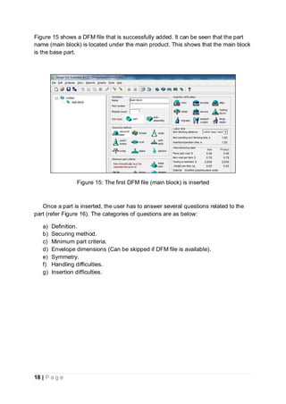
2. Simplify the structure of a product.
3. Provide good design practices to the designer.
The DFMA software offers a huge savings in time and money. It will assist in the
decision making process for a product design. Another interesting point, the user has
the ability to generate several design options in order to do some comparison. This
software also has one of the most extensive libraries for product’s materials,
production processes, fasteners and additional production operations.
Additionally, this software is a great tool for forecasting and the input or
parameter can be customized in order to fit an actual manufacturing enterprise.
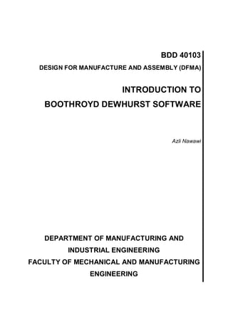
Preparation before using the DFMA software
In order to start using the DFMA software, the user needs to do some preparations.
i. The user needs to identify a product that will be studied in this lab. For
beginners, a product that consists of 30 to 50 parts is suitable.
ii. After the product is identified and approved by the lab instructor, the user can
start by following a flow chart in Figure 1.](https://image.slidesharecdn.com/dfmalabmodule1-180920163212/85/Dfma-lab-module-1-5-320.jpg)
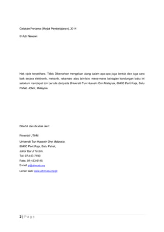
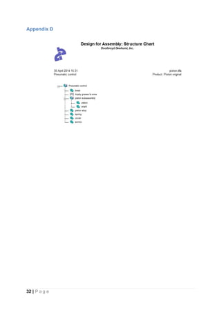
![8 | P a g e
Figure 4: An example of a structure chart
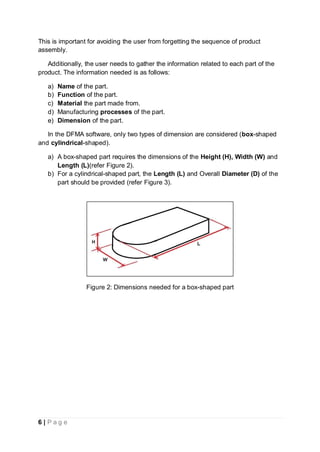
Steps to use DFMA software
The Boothroyd Dewhurst DFMA software is divided into two main components (DFM
and DFA). DFM stands for Design for Manufacture while DFA is for Design for
Assembly.
DFM analysis needs to be done on all parts except the standard fasteners
such as screws, bolts, nuts and washers because the data regarding these fasteners
are available in the software’s library.
DFM Software
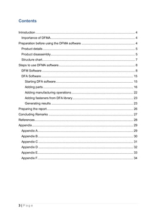
In this module, an example of product will be used for the purpose of explanation [2].
Figure 5 shows a piston-assembly design before the DFMA process. For the DFM
software explanation, the Main block (refer the most bottom part) is used as an
example.](https://image.slidesharecdn.com/dfmalabmodule1-180920163212/85/Dfma-lab-module-1-9-320.jpg)
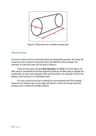
![9 | P a g e
Figure 5: Piston-assembly design [2]
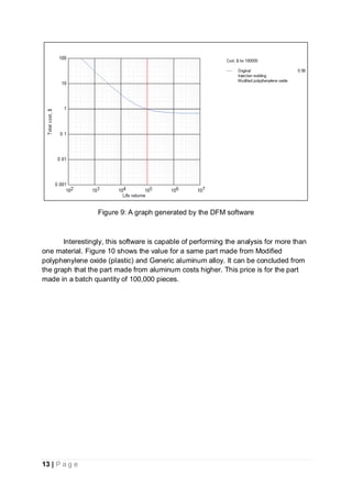
The DFM software is useful for investigating the quantitative effects on
changing a part’s material and manufacturing process [3]. The main output of DFM is](https://image.slidesharecdn.com/dfmalabmodule1-180920163212/85/Dfma-lab-module-1-10-320.jpg)
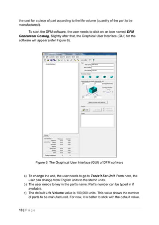

![15 | P a g e
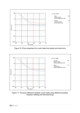
In the same way, the user can also compare the part’s price between different
manufacturing processes (refer Figure 11). This feature is very useful for the decision
making process.
It is also worth to note that, one part should have a DFM file (analysis). As a
result, if a product has 30 parts, there should be 30 DFM analyses.
a) It is advised to divide the parts equally between group members.
b) Once all DFM analyses are completed, the user can proceed to the
DFA software. In the DFA software, the user will assemble or gather the
parts together to form the product.
c) From here, a good structure chart will be very helpful.
DFA Software
The DFA software is used evaluate the assembly process of a product. It is in this
software, where the user is suggested to eliminate or combine the parts. The main
goal of this software is to simplify the assembly process so that the time and cost can
be reduced [4].
Starting DFA software
To start the software, the user needs to click on the icon named Design for
Assembly. The GUI for the DFA software is shown in Figure 12. In the software:
a) The user can change the Units from English to Metrics in the Settings box.
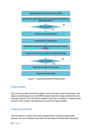
b) Next, the name of the product can be typed in the Name textbox.](https://image.slidesharecdn.com/dfmalabmodule1-180920163212/85/Dfma-lab-module-1-16-320.jpg)

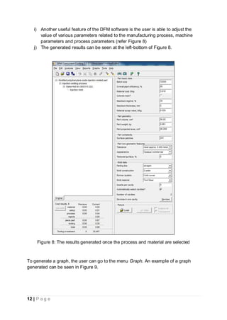
![26 | P a g e
Figure 23: The improved design of a piston-assembly design [2]
Preparing the report
The final stage of this project is to prepare a report. The format for the report is
presented in Table 1.](https://image.slidesharecdn.com/dfmalabmodule1-180920163212/85/Dfma-lab-module-1-27-320.jpg)
![28 | P a g e
References
[1] G. Lucchetta, et al., "Integrated design analysis for product simplification," CIRP Annals-
Manufacturing Technology, vol. 54, pp. 147-150, 2005.
[2] G. Boothroyd and P. Dewhurst, Product design for assembly: Boothroyd Dewhurst
Incorporated, 1991.
[3] B. D. Inc., DFM Concurrent Costing vol. Version 2.3. Rhode Island: Boothroyd Dewhurst Inc.,
2009.
[4] B. D. Inc., Design for Assembly vol. Version 9.4. Rhode Island: Boothroyd Dewhurst Inc., 2009.](https://image.slidesharecdn.com/dfmalabmodule1-180920163212/85/Dfma-lab-module-1-29-320.jpg)


![[Deck] What's New in Spark-Iceberg Integration via DSV2.pptx](https://cdn.slidesharecdn.com/ss_thumbnails/deckwhatsnewinspark-icebergintegrationviadsv2-260210005337-25955b12-thumbnail.jpg?width=640&height=640&fit=bounds)


