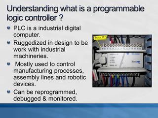
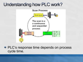
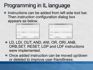
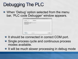
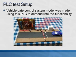
R.J.K.U Niroshan Ranatunga,
M.Sc. in Applied Electronics,
University of Colombo
Development of a low cost working model of
Programmable Logic controller(PLC) device
which implements the basic functionality of
commercially available industrial grade highly
branded products.
PLC is a industrial digital
computer.
Ruggedized in design to be
work with industrial
machineries.
Mostly used to control
manufacturing processes,
assembly lines and robotic
devices.
Can be reprogrammed,
debugged & monitored.
PLC’s response time depends on process
cycle time.
There are several PLC language standards
available under IEC61131 standard.
They are Ladder diagram, Function block
diagram, structured text, Instruction list and
Sequential function chart.
Compatibility between Ladder diagram and
Instruction List is shown in below example.
8 isolated logical inputs withstand up to 24V.
8 relay outputs.
Communication to PC over USB to serial COM.
PC software to program the PLC in Instruction
List language.
Standalone operation after once programmed.
Operate with 12-24VDC supply.
LED indicators for input/output status.
Circuit block diagram
Firmware code block diagram
Arduino Nano Rev.3 board used which
contains an ATMEGA328P microcontroller.
Circuit was designed in Altium deisgner 10.
PCB was fabricated in toner transfer method.
All component assembled PLC unit shown
below.
ATMEGA328P microcontroller programmed with
winavr gcc-c compiler.
EEPROM used as PLC instruction memory.
It was given ability to reprogram the EEPROM of
the microcontroller itself with new PLC
instruction data received through the serial Port.
In PLC process cycle, It fetches 16-bit instruction
from EEPROM. Then decode it and executes.
8 logical input status reading with edge
detection.
8 x 16-bit up counters.
8 x 16-bit timers(1ms x 2, 10ms x2, 100ms x 4)
13 Instruction list op-codes implemented.
PLC data stack implemented to transfer data
between instructions to form a logical network.
‘Simple PLC System’ software developed in C#
.Net language to provide code editor, program
and debug functionalities to the PLC hardware.
Instructions can be added from left side tool bar.
Then instruction configuration dialog box
appears as below.
LD, LDI, OUT, AND, ANI, OR, ORI, ANB,
ORB,SET, RESET, LDP and LDF instructions
were implemented.
Once added instruction can be moved up/down
or deleted to improve user friendliness.
User coded instruction list can be saved to
XML file with .PIL extension which is possible
to reopened into Instruction List code editor.
“build” or “Build and Upload” options in the
menu bar starts the build process.
First, It will be passed through an error
checker.
Then it will be built to unsigned integer array.
And saved to .hex file with hex values.
If it was “Build and Upload” process, on
successful build It will appear ‘Upload to PLC’
window.
If it was “Upload” option selected on menu bar,
Directly pops ‘Upload to PLC’ window. Then
the user has to select .hex file to upload.
When ‘Debug’ option selected from the menu
bar, ‘PLC code Debugger’ window appears.
It should be connected in correct COM port.
Single process cycle and continuous process
modes available.
It will be much slower processing in debug mode
Vehicle gate control system model was made
using this PLC to demonstrate the functionality.
New PLC device developed under 10% of the
cost of a commercially available PLC device.
This PLC device has fixed input output count.
But there are several commercial PLCs which
have modular I/O expansion capability.
Programming in Instruction List Language is
much harder when compared to other languages
such as Ladder logic, structured text.
This PLC has 7-15us instruction execution
speed. But commercial devices are much faster.
Implement other PLC languages like Ladder
logic, Structured text and etc.
Develop modular Input / Output cards which
can be cascade with main processing unit.
Develop modules with analog I/O capability.
Improve the processing power to speed up the
execution.
Increase internally available recourses like
Variables, Timers and Counters.
Having a ruggedized enclosure.
Development of plc
Development of plc

Development of plc

  • 1.
    R.J.K.U Niroshan Ranatunga, M.Sc.in Applied Electronics, University of Colombo
  • 2.
    Development of alow cost working model of Programmable Logic controller(PLC) device which implements the basic functionality of commercially available industrial grade highly branded products.
  • 3.
    PLC is aindustrial digital computer. Ruggedized in design to be work with industrial machineries. Mostly used to control manufacturing processes, assembly lines and robotic devices. Can be reprogrammed, debugged & monitored.
  • 4.
    PLC’s response timedepends on process cycle time.
  • 5.
    There are severalPLC language standards available under IEC61131 standard. They are Ladder diagram, Function block diagram, structured text, Instruction list and Sequential function chart. Compatibility between Ladder diagram and Instruction List is shown in below example.
  • 6.
    8 isolated logicalinputs withstand up to 24V. 8 relay outputs. Communication to PC over USB to serial COM. PC software to program the PLC in Instruction List language. Standalone operation after once programmed. Operate with 12-24VDC supply. LED indicators for input/output status.
  • 7.
  • 8.
    Arduino Nano Rev.3board used which contains an ATMEGA328P microcontroller. Circuit was designed in Altium deisgner 10. PCB was fabricated in toner transfer method. All component assembled PLC unit shown below.
  • 9.
    ATMEGA328P microcontroller programmedwith winavr gcc-c compiler. EEPROM used as PLC instruction memory. It was given ability to reprogram the EEPROM of the microcontroller itself with new PLC instruction data received through the serial Port. In PLC process cycle, It fetches 16-bit instruction from EEPROM. Then decode it and executes.
  • 10.
    8 logical inputstatus reading with edge detection. 8 x 16-bit up counters. 8 x 16-bit timers(1ms x 2, 10ms x2, 100ms x 4) 13 Instruction list op-codes implemented. PLC data stack implemented to transfer data between instructions to form a logical network.
  • 11.
    ‘Simple PLC System’software developed in C# .Net language to provide code editor, program and debug functionalities to the PLC hardware.
  • 12.
    Instructions can beadded from left side tool bar. Then instruction configuration dialog box appears as below. LD, LDI, OUT, AND, ANI, OR, ORI, ANB, ORB,SET, RESET, LDP and LDF instructions were implemented. Once added instruction can be moved up/down or deleted to improve user friendliness.
  • 13.
    User coded instructionlist can be saved to XML file with .PIL extension which is possible to reopened into Instruction List code editor. “build” or “Build and Upload” options in the menu bar starts the build process. First, It will be passed through an error checker. Then it will be built to unsigned integer array. And saved to .hex file with hex values.
  • 14.
    If it was“Build and Upload” process, on successful build It will appear ‘Upload to PLC’ window. If it was “Upload” option selected on menu bar, Directly pops ‘Upload to PLC’ window. Then the user has to select .hex file to upload.
  • 15.
    When ‘Debug’ optionselected from the menu bar, ‘PLC code Debugger’ window appears. It should be connected in correct COM port. Single process cycle and continuous process modes available. It will be much slower processing in debug mode
  • 16.
    Vehicle gate controlsystem model was made using this PLC to demonstrate the functionality.
  • 17.
    New PLC devicedeveloped under 10% of the cost of a commercially available PLC device. This PLC device has fixed input output count. But there are several commercial PLCs which have modular I/O expansion capability. Programming in Instruction List Language is much harder when compared to other languages such as Ladder logic, structured text. This PLC has 7-15us instruction execution speed. But commercial devices are much faster.
  • 18.
    Implement other PLClanguages like Ladder logic, Structured text and etc. Develop modular Input / Output cards which can be cascade with main processing unit. Develop modules with analog I/O capability. Improve the processing power to speed up the execution. Increase internally available recourses like Variables, Timers and Counters. Having a ruggedized enclosure.