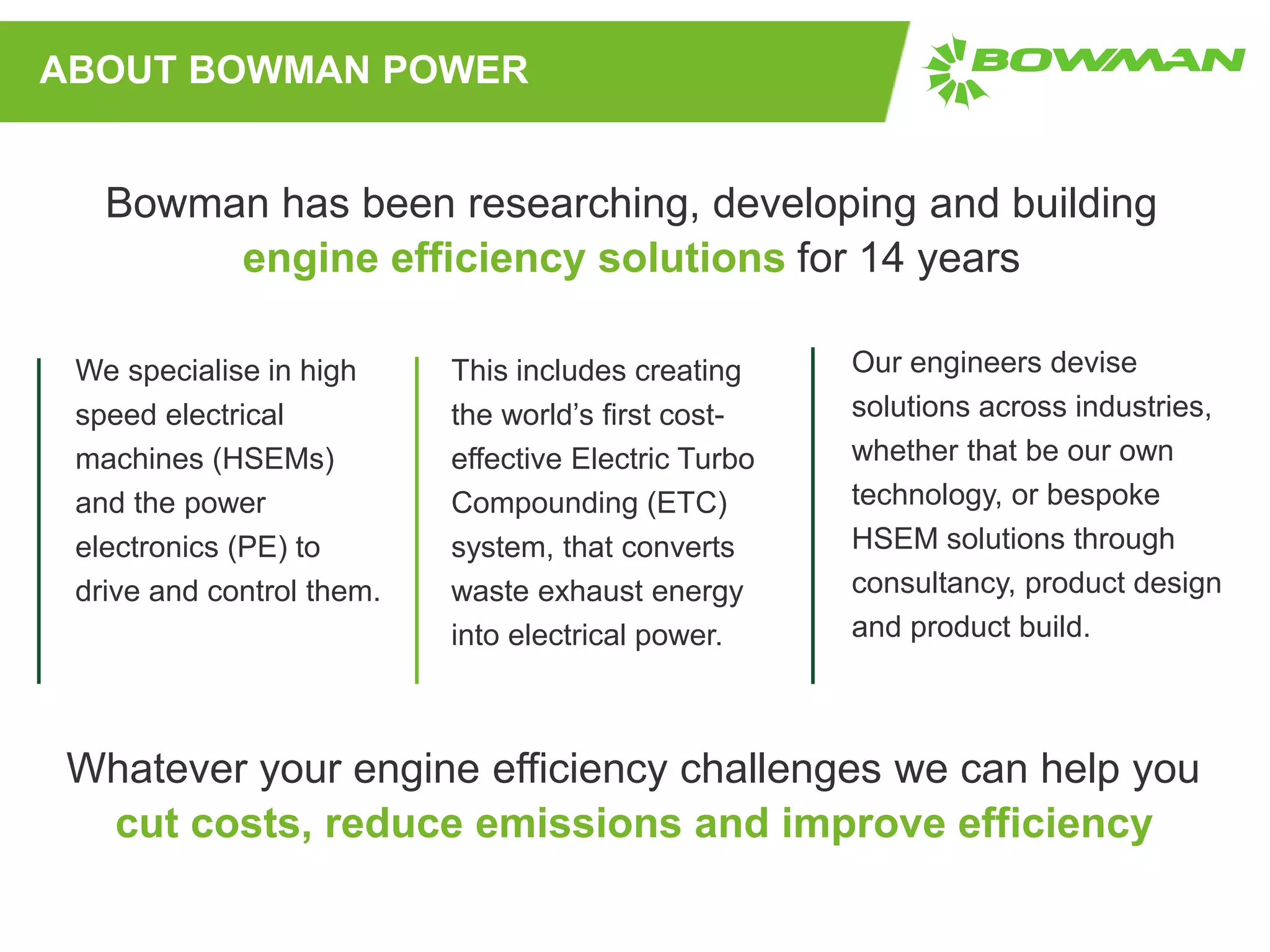
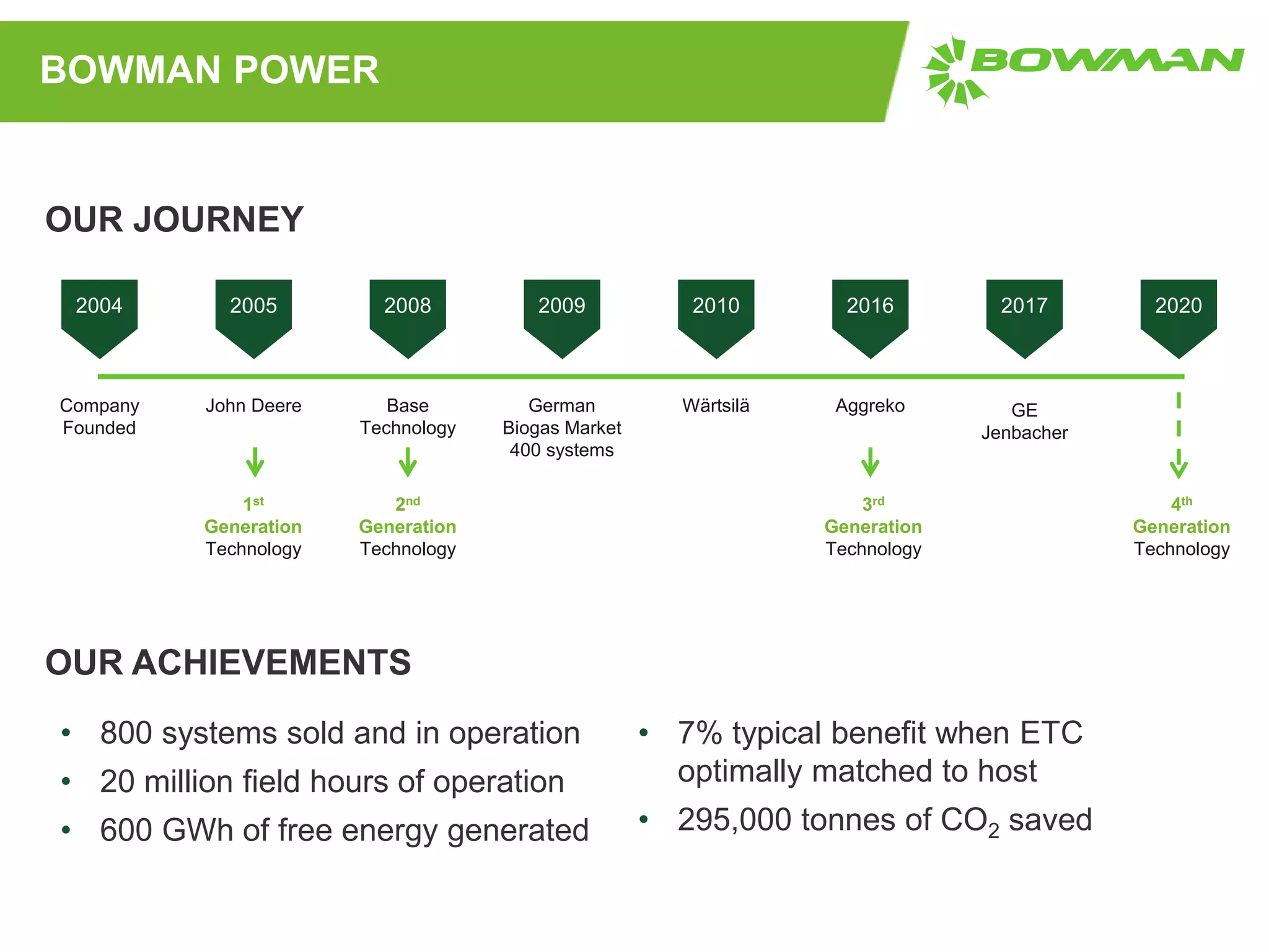
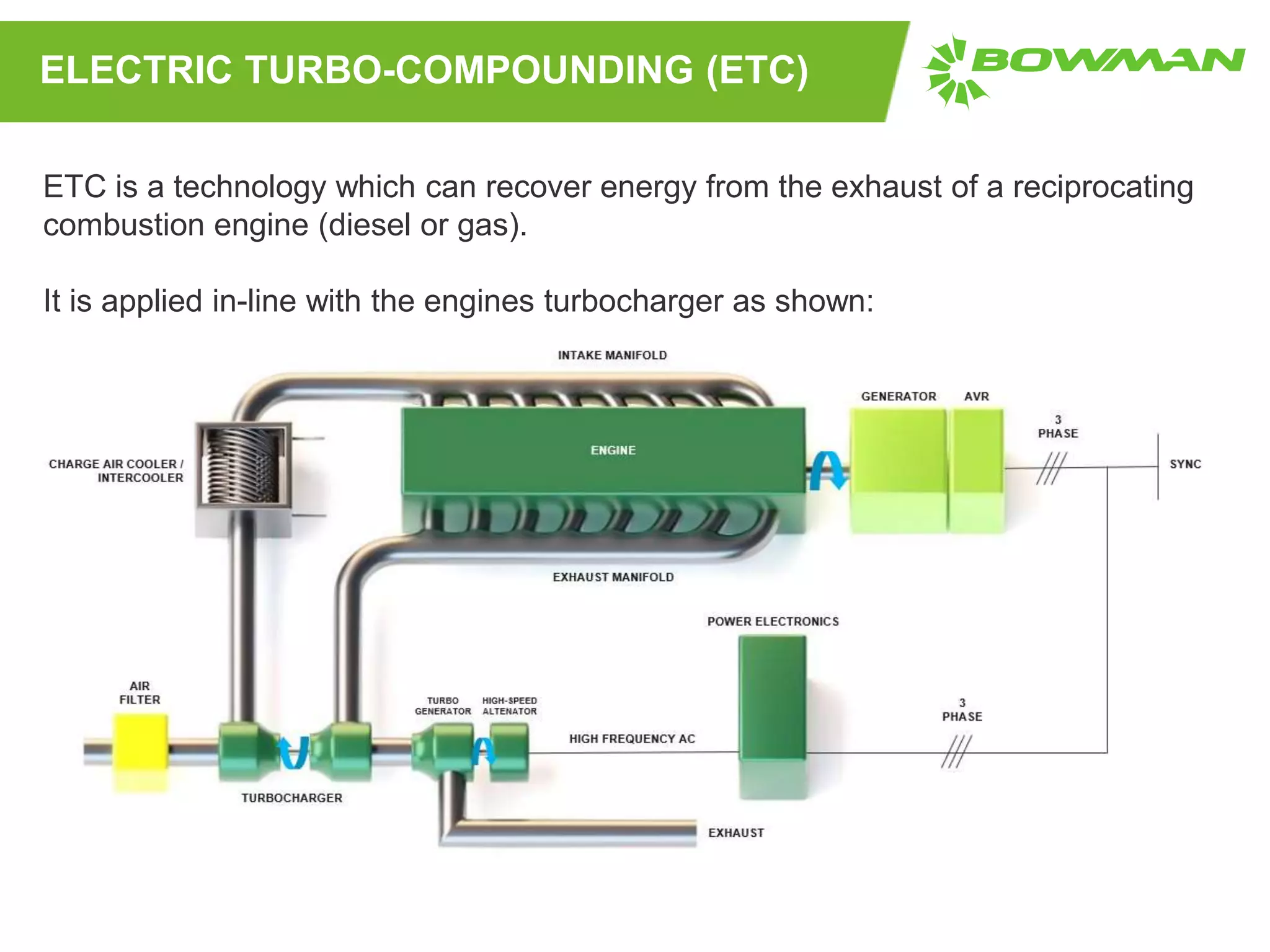
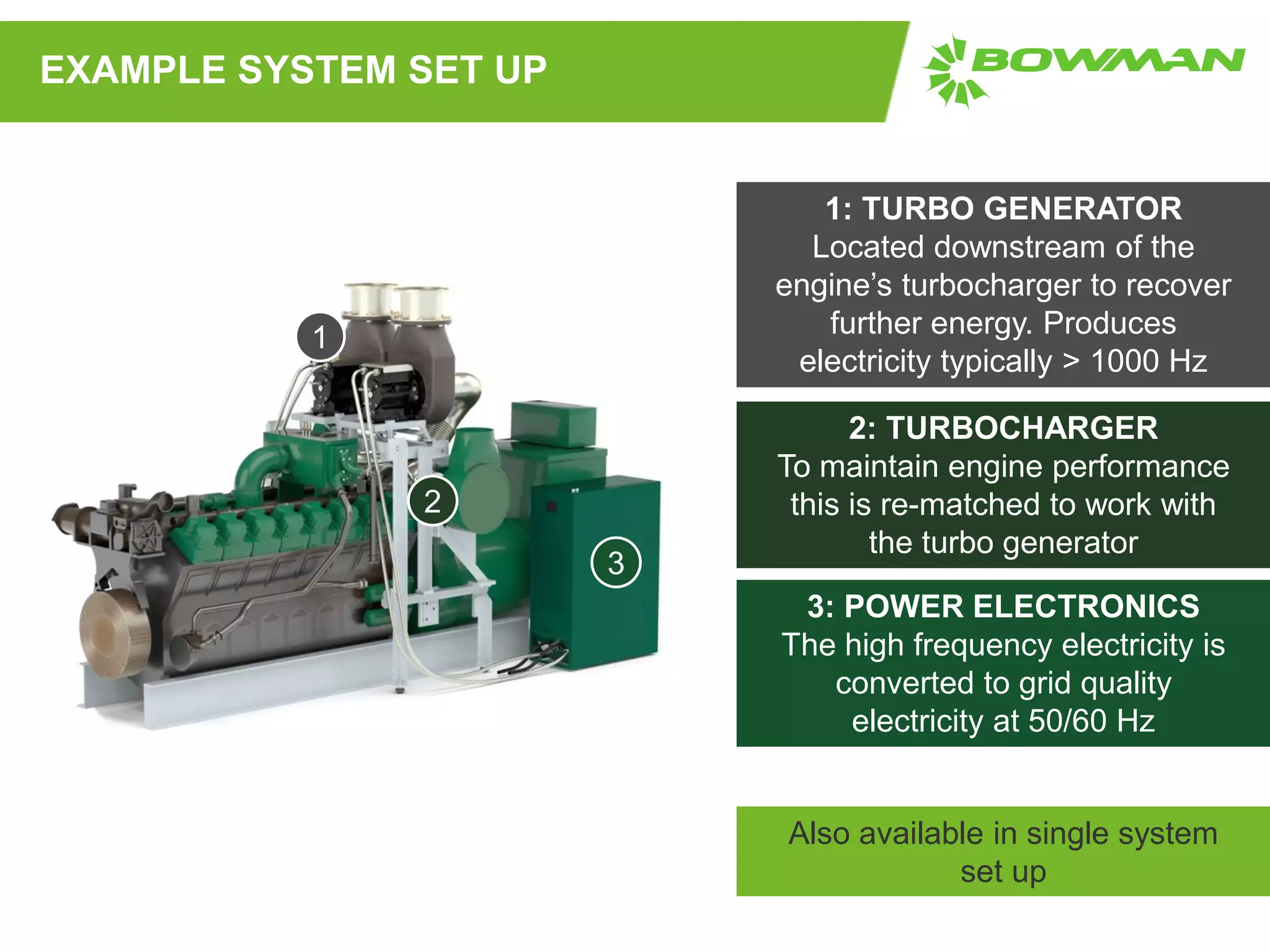
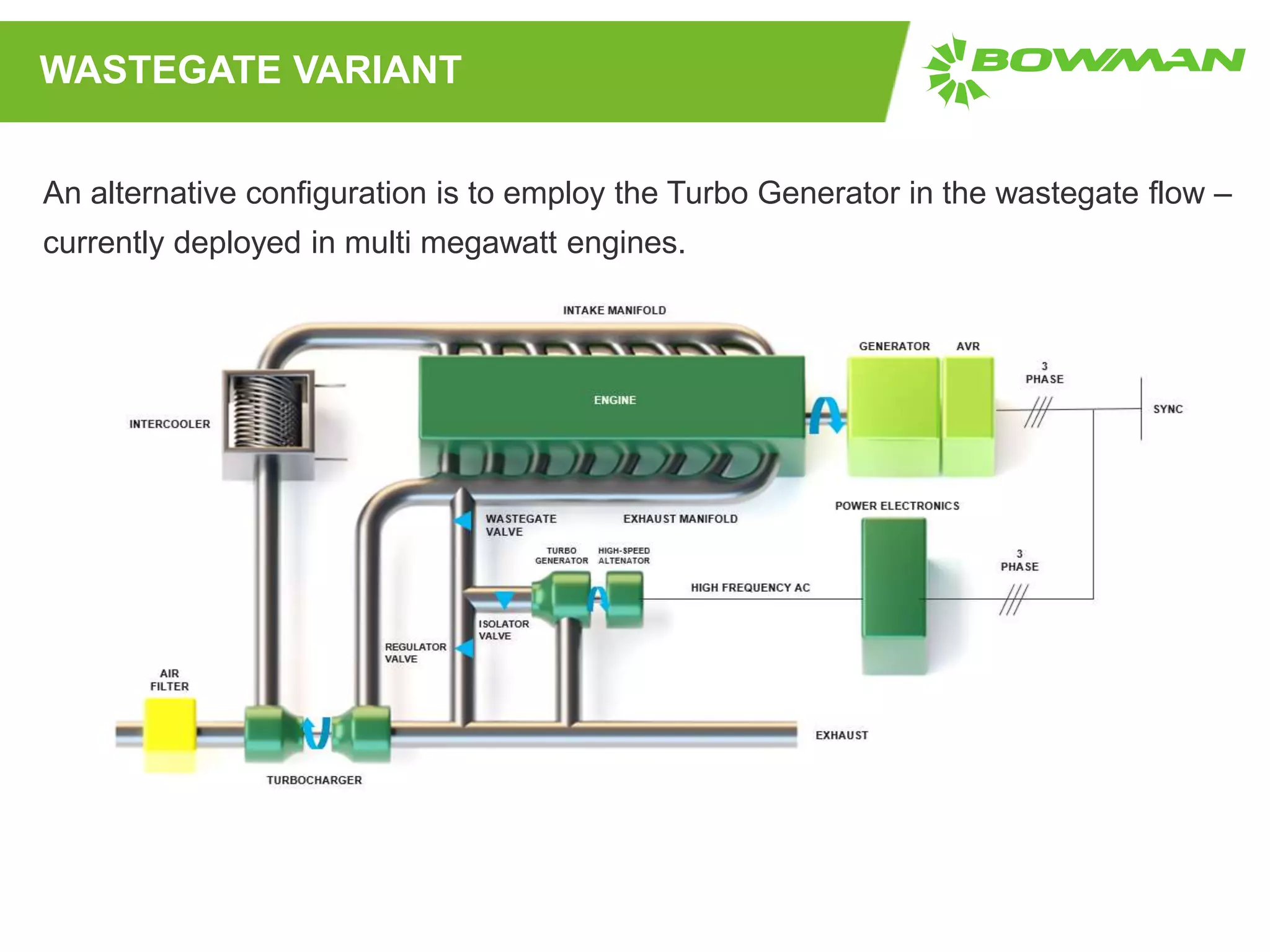
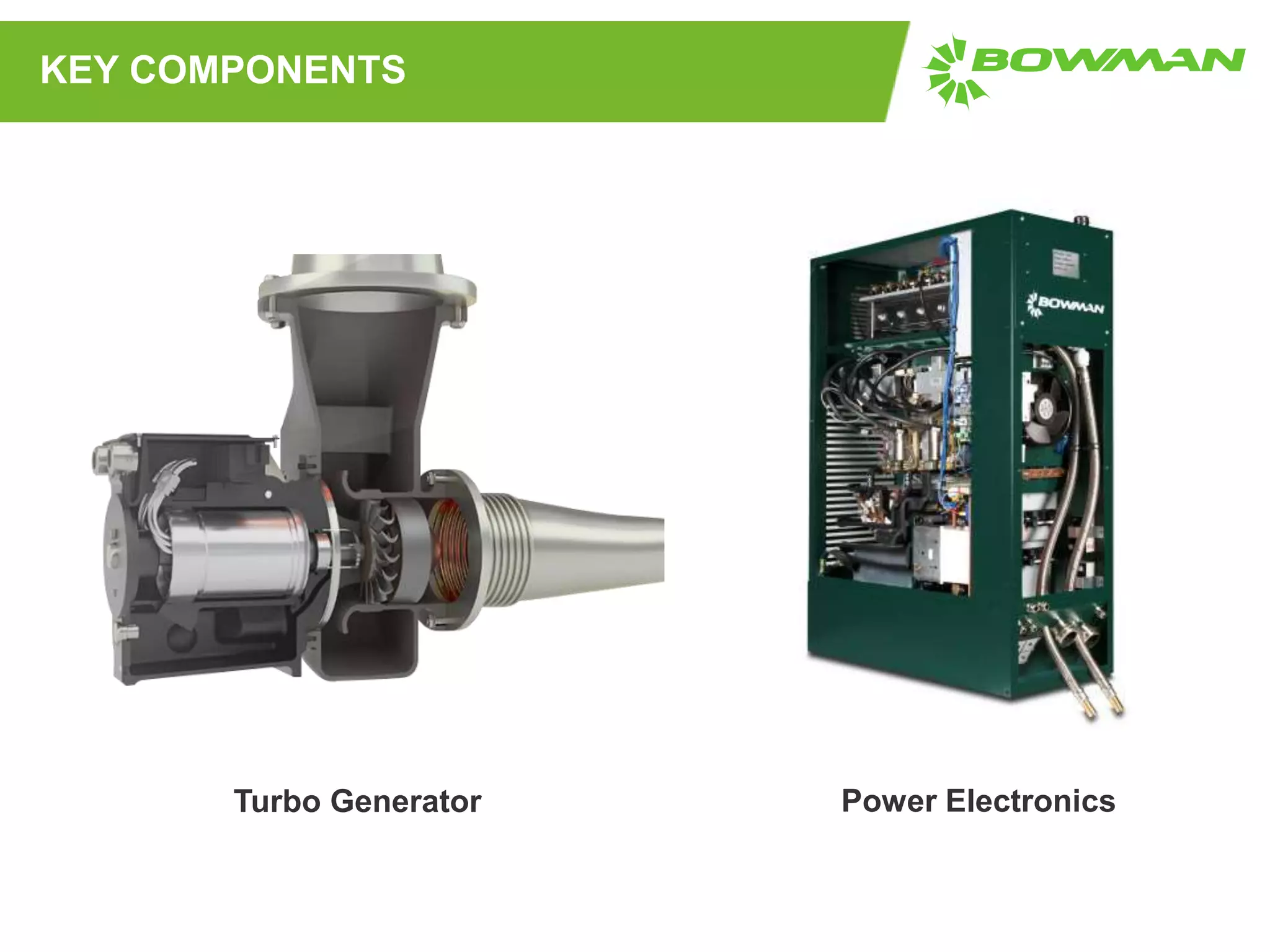
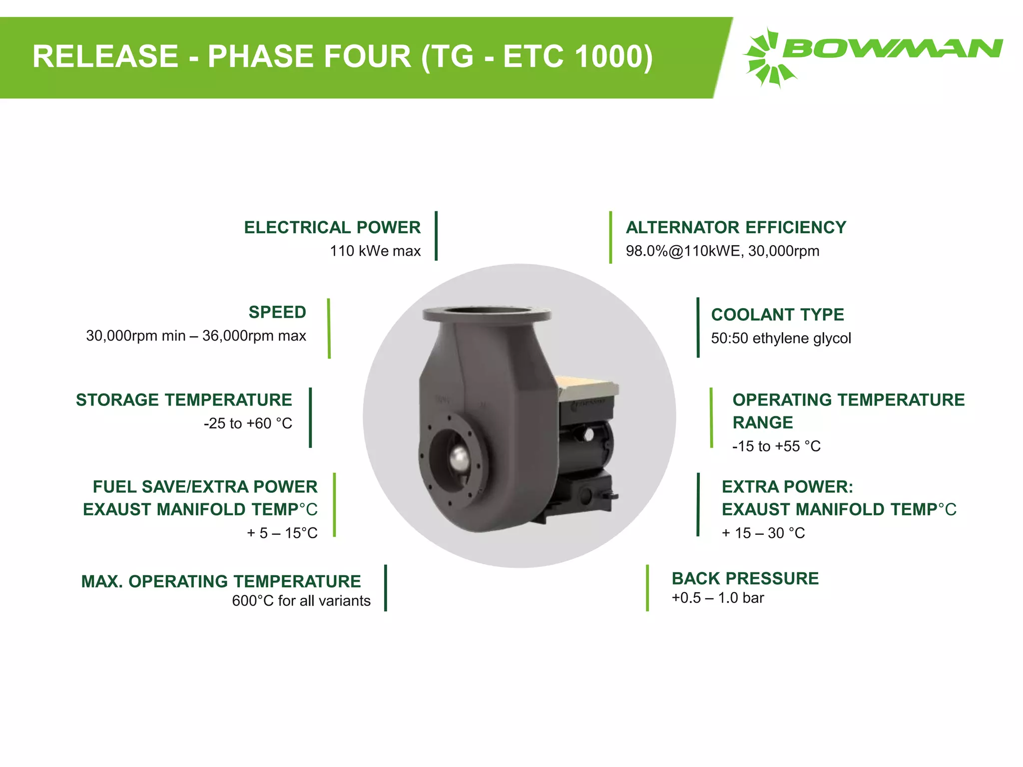
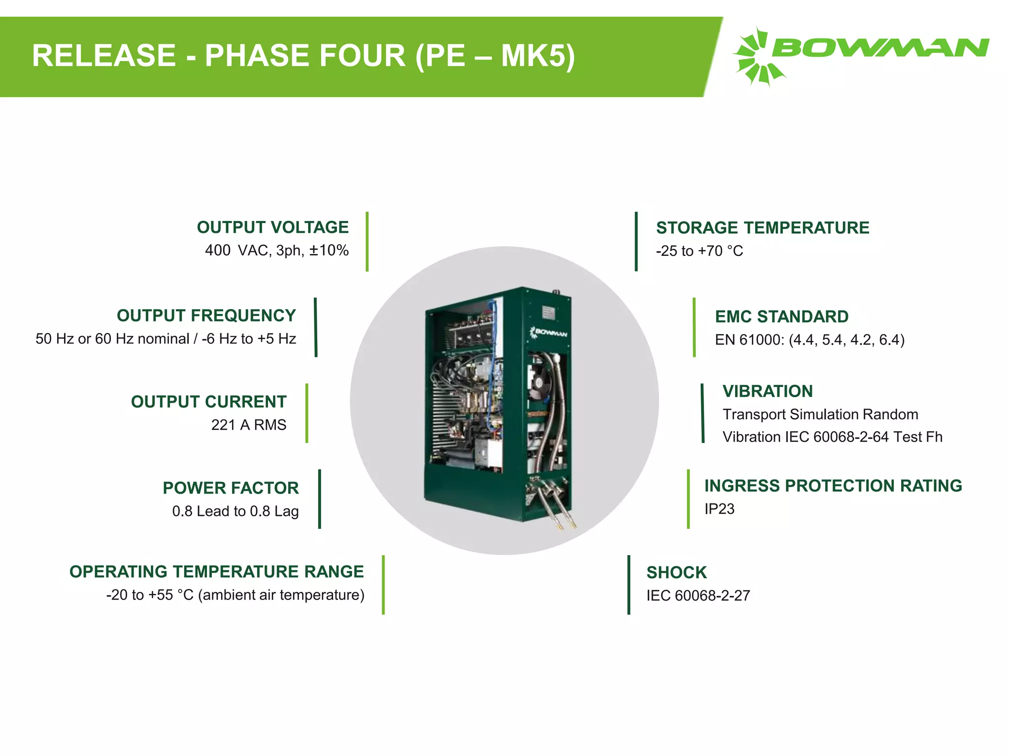
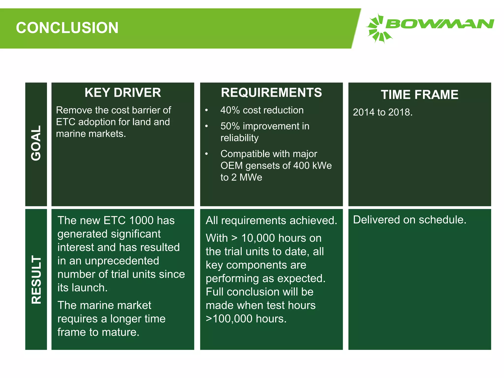
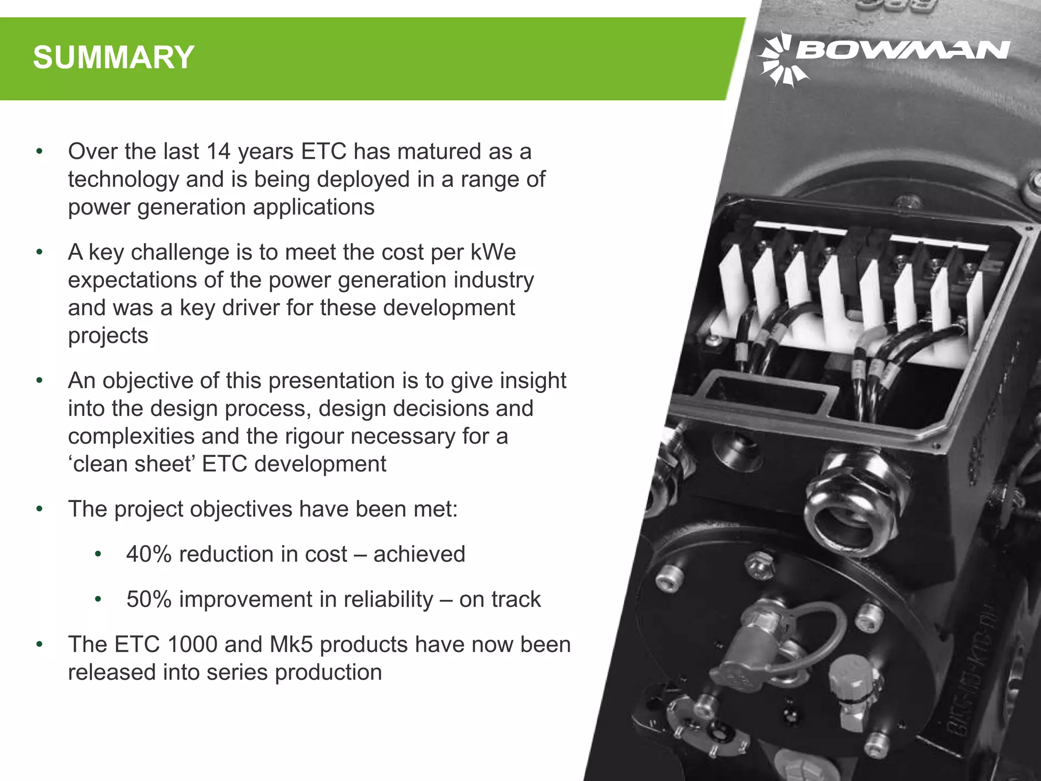
WWW.BOWMANPOWER.COM
NEW GENERATION OF ELECTRIC
TURBO COMPOUNDING (ETC)
FOR RECIPROCATING ENGINE
GENERATOR SETS
Dr Shinri Szymko
Head of Engineering
Power-Gen Asia 18
Jakarta, Indonesia
• About Bowman Power
• What is ETC (Electric Turbo-compounding)?
• ETC – Generation 3
• Development process
• Development key decisions
• Case study
AGENDA
ABOUT BOWMAN POWER
We specialise in high
speed electrical
machines (HSEMs)
and the power
electronics (PE) to
drive and control them.
This includes creating
the world’s first cost-
effective Electric Turbo
Compounding (ETC)
system, that converts
waste exhaust energy
into electrical power.
Our engineers devise
solutions across industries,
whether that be our own
technology, or bespoke
HSEM solutions through
consultancy, product design
and product build.
Bowman has been researching, developing and building
engine efficiency solutions for 14 years
Whatever your engine efficiency challenges we can help you
cut costs, reduce emissions and improve efficiency
BOWMAN POWER
2004 2005 2008 2009 2010 2016 2017 2020
Company
Founded
John Deere Base
Technology
German
Biogas Market
400 systems
Wärtsilä Aggreko GE
Jenbacher
1st
Generation
Technology
2nd
Generation
Technology
3rd
Generation
Technology
4th
Generation
Technology
OUR JOURNEY
OUR ACHIEVEMENTS
• 800 systems sold and in operation
• 20 million field hours of operation
• 600 GWh of free energy generated
• 7% typical benefit when ETC
optimally matched to host
• 295,000 tonnes of CO2 saved
ELECTRIC TURBO-COMPOUNDING (ETC)
ETC is a technology which can recover energy from the exhaust of a reciprocating
combustion engine (diesel or gas).
It is applied in-line with the engines turbocharger as shown:
EXAMPLE SYSTEM SET UP
1: TURBO GENERATOR
Located downstream of the
engine’s turbocharger to recover
further energy. Produces
electricity typically > 1000 Hz
3: POWER ELECTRONICS
The high frequency electricity is
converted to grid quality
electricity at 50/60 Hz
Also available in single system
set up
2: TURBOCHARGER
To maintain engine performance
this is re-matched to work with
the turbo generator
2
1
3
WASTEGATE VARIANT
An alternative configuration is to employ the Turbo Generator in the wastegate flow –
currently deployed in multi megawatt engines.
KEY COMPONENTS
Turbo Generator Power Electronics
ETC SYSTEM
DEVELOPMENT
PROGRAMME OUTLINE
PROJECT SCOPE
A clean sheet ETC
system.
KEY DRIVER
Remove the price barrier
of ETC adoption for land
and marine markets.
REQUIREMENTS
• 40% price reduction
• 50% improvement in
reliability
• Compatible with major
OEM gensets of 400
kWe to 2 MWe.
PARTNERS
• Cummins
• Rolls Royce
• Lloyds Register
• University College
London
FUNDING
• DECC UK – Turbo
Generator
• Innovate UK – Power
Electronics
• Internal funding
TIME FRAME
2014 to 2018.
A gate process provides the rigour necessary to
ensure quality and efficiency is maintained on such
a large project.
Bowman’s ‘New Product Introduction’ (NPI)
process includes five phases, from opportunity to
production:
PHASE GATES
• Phase 0 – Opportunity
• Phase 1 – Concept
• Phase 2 – Design
• Phase 3 – Validation
• Phase 4 – Release to production
PHASE 1:
CONCEPT
KEY DECISIONS - PHASE ONE
The first key design decision and the one with the largest business implications:
What power rating should the ETC system be?
Performance
Model
Cost
Model
Pricing
Model
Value
Model
Market
Sensitivity
Identify key
gensets and
develop system
performance
models to allow a
performance
sweep to be
conducted.
Develop a bottom
up (‘should cost’)
cost model of the
system (TG, PE,
support & mounting
systems and PAT
testing) as a
function of the
power output.
Develop a top
down price model
to understand
target pricing.
(Not presented
here)
Develop an overall
value model
(impact analysis of
“frozen design”
case scenarios)
Develop a market
sensitivity model to
assess the effect of
variations to
expected design
points.
(Not presented
here)
CUSTOMER VALUE - PHASE ONE
Conclusion: 110 kWe is the optimum power rating
Normalised Fitness Function =
SFC reduction (%)
Total cost of the system from the customer point of view
Genset cost including hardware and maintenance
Overall Fitness Function =
all engines
Market fractioni ∙ Normalised Fitness Functioni
PHASE 2:
DESIGN
TURBINE CHOICE - PHASE TWO
• Turbine type choice
• Radial flow turbine
• Axial flow turbine
• Key criteria
• Performance
• Function
• Cost
• Geometrical statistics of the radial
machine compared to the axial
machine:
• Radial turbine is 20% larger in
diameter
• Radial turbine is 300% heavier
• Electrical machine is 100% larger
in volume
• Radial turbine rotates 30% slower
TURBINE CHOICE - PHASE TWO
• Performance
• Affects of ambient temperature and
altitude
• Engine fleet variation effects
• Engine part load
• Cost
• Number of NGVs
• Number of turbines
• Turbine castings size
• Electrical machine size
• Function
• Rotor dynamics
• Heat transfer
• Bearing and thrust loading
• Electrical machine function
Conclusion: An axial flow turbine is the
optimum solution
POWER ELECTRONICS – PHASE TWO
• Key decision – Switching frequency
of the power electronics?
• Effects size and cost of
components
• The power electronic system is
constructed with:
• Active components – such as the
power electronics
• Passive components – such as
the power inductors and
capacitors
• Faster switching allows the passive
components to become smaller but
results in a higher cost
Conclusion: For industrial applications – lower
switching frequencies are most cost effective.
PHASE 3:
VALIDATION
VALIDATION - PHASE THREE
Validation is extremely important and
one of the most costly parts of
development:
• Gas stand testing (performance and
safety function)
• Functional testing (vibration, EMC,
ingress protection, burst testing)
• On engine-testing (Cummins
QSK60)
• Operational environment testing
(endurance testing)
• EDL, Aggreko and Anglian
Water
• 3rd Party/standards testing
• Grid codes
PHASE 4:
RELEASE TO PRODUCTION
RELEASE TO PRODUCTION - PHASE FOUR
• To ensure the product and system can be
reliably manufactured, assembled and
tested by production
• This is an important stage, where Bill of
Materials are released. Any changes are
controlled under an Engineering Change
process
• Large check list of processes is released:
• Supplier validation, quality checks and
processes are complete as well as the
release of the production tooling and
build processes
• Internal teams and customers, training,
documentation and manuals are released
Weight: 255kg
ELECTRICAL POWER
110 kWe max
SPEED
30,000rpm min – 36,000rpm max
STORAGE TEMPERATURE
-25 to +60 °C
ALTERNATOR EFFICIENCY
98.0%@110kWE, 30,000rpm
OPERATING TEMPERATURE
RANGE
-15 to +55 °C
COOLANT TYPE
50:50 ethylene glycol
FUEL SAVE/EXTRA POWER
EXAUST MANIFOLD TEMP°C
+ 5 – 15°C
EXTRA POWER:
EXAUST MANIFOLD TEMP°C
+ 15 – 30 °C
MAX. OPERATING TEMPERATURE
600°C for all variants
BACK PRESSURE
+0.5 – 1.0 bar
RELEASE - PHASE FOUR (TG - ETC 1000)
STORAGE TEMPERATURE
-25 to +70 °C
EMC STANDARD
EN 61000: (4.4, 5.4, 4.2, 6.4)
OUTPUT VOLTAGE
400 VAC, 3ph, ±10%
OUTPUT FREQUENCY
50 Hz or 60 Hz nominal / -6 Hz to +5 Hz
OUTPUT CURRENT
221 A RMS
POWER FACTOR
0.8 Lead to 0.8 Lag
OPERATING TEMPERATURE RANGE
-20 to +55 °C (ambient air temperature)
VIBRATION
Transport Simulation Random
Vibration IEC 60068-2-64 Test Fh
SHOCK
IEC 60068-2-27
INGRESS PROTECTION RATING
IP23
RELEASE - PHASE FOUR (PE – MK5)
The new ETC 1000 has
generated significant
interest and has resulted
in an unprecedented
number of trial units since
its launch.
The marine market
requires a longer time
frame to mature.
All requirements achieved.
With > 10,000 hours on
the trial units to date, all
key components are
performing as expected.
Full conclusion will be
made when test hours
>100,000 hours.
Delivered on schedule.
CONCLUSION
KEY DRIVER
Remove the cost barrier of
ETC adoption for land and
marine markets.
REQUIREMENTS
• 40% cost reduction
• 50% improvement in
reliability
• Compatible with major
OEM gensets of 400 kWe
to 2 MWe
TIME FRAME
2014 to 2018.
GOALRESULT
ETC CASE STUDY
OVERVIEW
• We are trialling a demonstrator ETC 1000
on a Caterpillar 3516 gas engine
• Located at a 97 MW power generation
facility
• Focused on Waste Coal Mine Gas (WCMG)
• WCMG is a hazardous by-product of coal
mining, where trapped methane is released
from within the coal seams into the coal
mine
• Gas is burnt in a gas powered reciprocating
generator set and electricity is supplied to
the grid
• The ETC 1000 was installed in six days
RESULTS
With the ETC 1000 installed. The engine
runs as before but with an additional
power output:
• 7.35% increase in electrical efficiency
• 2.70% increase in thermal efficiency
• Run hours - >6,500 hours
• 465,000 kWh generated
Example 6 week operation:
• Mean engine load ~ 79%
• Mean ETC power ~ 9.5% of main
generator set power
Next steps: Generator set will continue to
run to gather data.
SUMMARY
SUMMARY
• Over the last 14 years ETC has matured as a
technology and is being deployed in a range of
power generation applications
• A key challenge is to meet the cost per kWe
expectations of the power generation industry
and was a key driver for these development
projects
• An objective of this presentation is to give insight
into the design process, design decisions and
complexities and the rigour necessary for a
‘clean sheet’ ETC development
• The project objectives have been met:
• 40% reduction in cost – achieved
• 50% improvement in reliability – on track
• The ETC 1000 and Mk5 products have now been
released into series production
WWW.BOWMANPOWER.COM
THANK YOU FOR
YOUR TIME
For more information visit:

Developing a new generation of energy efficiency products for reciprocating engine generator sets

  • 1.
    WWW.BOWMANPOWER.COM NEW GENERATION OFELECTRIC TURBO COMPOUNDING (ETC) FOR RECIPROCATING ENGINE GENERATOR SETS Dr Shinri Szymko Head of Engineering Power-Gen Asia 18 Jakarta, Indonesia
  • 2.
    • About BowmanPower • What is ETC (Electric Turbo-compounding)? • ETC – Generation 3 • Development process • Development key decisions • Case study AGENDA
  • 3.
    ABOUT BOWMAN POWER Wespecialise in high speed electrical machines (HSEMs) and the power electronics (PE) to drive and control them. This includes creating the world’s first cost- effective Electric Turbo Compounding (ETC) system, that converts waste exhaust energy into electrical power. Our engineers devise solutions across industries, whether that be our own technology, or bespoke HSEM solutions through consultancy, product design and product build. Bowman has been researching, developing and building engine efficiency solutions for 14 years Whatever your engine efficiency challenges we can help you cut costs, reduce emissions and improve efficiency
  • 4.
    BOWMAN POWER 2004 20052008 2009 2010 2016 2017 2020 Company Founded John Deere Base Technology German Biogas Market 400 systems Wärtsilä Aggreko GE Jenbacher 1st Generation Technology 2nd Generation Technology 3rd Generation Technology 4th Generation Technology OUR JOURNEY OUR ACHIEVEMENTS • 800 systems sold and in operation • 20 million field hours of operation • 600 GWh of free energy generated • 7% typical benefit when ETC optimally matched to host • 295,000 tonnes of CO2 saved
  • 5.
    ELECTRIC TURBO-COMPOUNDING (ETC) ETCis a technology which can recover energy from the exhaust of a reciprocating combustion engine (diesel or gas). It is applied in-line with the engines turbocharger as shown:
  • 6.
    EXAMPLE SYSTEM SETUP 1: TURBO GENERATOR Located downstream of the engine’s turbocharger to recover further energy. Produces electricity typically > 1000 Hz 3: POWER ELECTRONICS The high frequency electricity is converted to grid quality electricity at 50/60 Hz Also available in single system set up 2: TURBOCHARGER To maintain engine performance this is re-matched to work with the turbo generator 2 1 3
  • 7.
    WASTEGATE VARIANT An alternativeconfiguration is to employ the Turbo Generator in the wastegate flow – currently deployed in multi megawatt engines.
  • 8.
  • 9.
  • 10.
    PROGRAMME OUTLINE PROJECT SCOPE Aclean sheet ETC system. KEY DRIVER Remove the price barrier of ETC adoption for land and marine markets. REQUIREMENTS • 40% price reduction • 50% improvement in reliability • Compatible with major OEM gensets of 400 kWe to 2 MWe. PARTNERS • Cummins • Rolls Royce • Lloyds Register • University College London FUNDING • DECC UK – Turbo Generator • Innovate UK – Power Electronics • Internal funding TIME FRAME 2014 to 2018.
  • 11.
    A gate processprovides the rigour necessary to ensure quality and efficiency is maintained on such a large project. Bowman’s ‘New Product Introduction’ (NPI) process includes five phases, from opportunity to production: PHASE GATES • Phase 0 – Opportunity • Phase 1 – Concept • Phase 2 – Design • Phase 3 – Validation • Phase 4 – Release to production
  • 12.
  • 13.
    KEY DECISIONS -PHASE ONE The first key design decision and the one with the largest business implications: What power rating should the ETC system be? Performance Model Cost Model Pricing Model Value Model Market Sensitivity Identify key gensets and develop system performance models to allow a performance sweep to be conducted. Develop a bottom up (‘should cost’) cost model of the system (TG, PE, support & mounting systems and PAT testing) as a function of the power output. Develop a top down price model to understand target pricing. (Not presented here) Develop an overall value model (impact analysis of “frozen design” case scenarios) Develop a market sensitivity model to assess the effect of variations to expected design points. (Not presented here)
  • 14.
    CUSTOMER VALUE -PHASE ONE Conclusion: 110 kWe is the optimum power rating Normalised Fitness Function = SFC reduction (%) Total cost of the system from the customer point of view Genset cost including hardware and maintenance Overall Fitness Function = all engines Market fractioni ∙ Normalised Fitness Functioni
  • 15.
  • 16.
    TURBINE CHOICE -PHASE TWO • Turbine type choice • Radial flow turbine • Axial flow turbine • Key criteria • Performance • Function • Cost • Geometrical statistics of the radial machine compared to the axial machine: • Radial turbine is 20% larger in diameter • Radial turbine is 300% heavier • Electrical machine is 100% larger in volume • Radial turbine rotates 30% slower
  • 17.
    TURBINE CHOICE -PHASE TWO • Performance • Affects of ambient temperature and altitude • Engine fleet variation effects • Engine part load • Cost • Number of NGVs • Number of turbines • Turbine castings size • Electrical machine size • Function • Rotor dynamics • Heat transfer • Bearing and thrust loading • Electrical machine function Conclusion: An axial flow turbine is the optimum solution
  • 18.
    POWER ELECTRONICS –PHASE TWO • Key decision – Switching frequency of the power electronics? • Effects size and cost of components • The power electronic system is constructed with: • Active components – such as the power electronics • Passive components – such as the power inductors and capacitors • Faster switching allows the passive components to become smaller but results in a higher cost Conclusion: For industrial applications – lower switching frequencies are most cost effective.
  • 19.
  • 20.
    VALIDATION - PHASETHREE Validation is extremely important and one of the most costly parts of development: • Gas stand testing (performance and safety function) • Functional testing (vibration, EMC, ingress protection, burst testing) • On engine-testing (Cummins QSK60) • Operational environment testing (endurance testing) • EDL, Aggreko and Anglian Water • 3rd Party/standards testing • Grid codes
  • 21.
  • 22.
    RELEASE TO PRODUCTION- PHASE FOUR • To ensure the product and system can be reliably manufactured, assembled and tested by production • This is an important stage, where Bill of Materials are released. Any changes are controlled under an Engineering Change process • Large check list of processes is released: • Supplier validation, quality checks and processes are complete as well as the release of the production tooling and build processes • Internal teams and customers, training, documentation and manuals are released
  • 23.
    Weight: 255kg ELECTRICAL POWER 110kWe max SPEED 30,000rpm min – 36,000rpm max STORAGE TEMPERATURE -25 to +60 °C ALTERNATOR EFFICIENCY 98.0%@110kWE, 30,000rpm OPERATING TEMPERATURE RANGE -15 to +55 °C COOLANT TYPE 50:50 ethylene glycol FUEL SAVE/EXTRA POWER EXAUST MANIFOLD TEMP°C + 5 – 15°C EXTRA POWER: EXAUST MANIFOLD TEMP°C + 15 – 30 °C MAX. OPERATING TEMPERATURE 600°C for all variants BACK PRESSURE +0.5 – 1.0 bar RELEASE - PHASE FOUR (TG - ETC 1000)
  • 24.
    STORAGE TEMPERATURE -25 to+70 °C EMC STANDARD EN 61000: (4.4, 5.4, 4.2, 6.4) OUTPUT VOLTAGE 400 VAC, 3ph, ±10% OUTPUT FREQUENCY 50 Hz or 60 Hz nominal / -6 Hz to +5 Hz OUTPUT CURRENT 221 A RMS POWER FACTOR 0.8 Lead to 0.8 Lag OPERATING TEMPERATURE RANGE -20 to +55 °C (ambient air temperature) VIBRATION Transport Simulation Random Vibration IEC 60068-2-64 Test Fh SHOCK IEC 60068-2-27 INGRESS PROTECTION RATING IP23 RELEASE - PHASE FOUR (PE – MK5)
  • 25.
    The new ETC1000 has generated significant interest and has resulted in an unprecedented number of trial units since its launch. The marine market requires a longer time frame to mature. All requirements achieved. With > 10,000 hours on the trial units to date, all key components are performing as expected. Full conclusion will be made when test hours >100,000 hours. Delivered on schedule. CONCLUSION KEY DRIVER Remove the cost barrier of ETC adoption for land and marine markets. REQUIREMENTS • 40% cost reduction • 50% improvement in reliability • Compatible with major OEM gensets of 400 kWe to 2 MWe TIME FRAME 2014 to 2018. GOALRESULT
  • 26.
  • 27.
    OVERVIEW • We aretrialling a demonstrator ETC 1000 on a Caterpillar 3516 gas engine • Located at a 97 MW power generation facility • Focused on Waste Coal Mine Gas (WCMG) • WCMG is a hazardous by-product of coal mining, where trapped methane is released from within the coal seams into the coal mine • Gas is burnt in a gas powered reciprocating generator set and electricity is supplied to the grid • The ETC 1000 was installed in six days
  • 28.
    RESULTS With the ETC1000 installed. The engine runs as before but with an additional power output: • 7.35% increase in electrical efficiency • 2.70% increase in thermal efficiency • Run hours - >6,500 hours • 465,000 kWh generated Example 6 week operation: • Mean engine load ~ 79% • Mean ETC power ~ 9.5% of main generator set power Next steps: Generator set will continue to run to gather data.
  • 29.
  • 30.
    SUMMARY • Over thelast 14 years ETC has matured as a technology and is being deployed in a range of power generation applications • A key challenge is to meet the cost per kWe expectations of the power generation industry and was a key driver for these development projects • An objective of this presentation is to give insight into the design process, design decisions and complexities and the rigour necessary for a ‘clean sheet’ ETC development • The project objectives have been met: • 40% reduction in cost – achieved • 50% improvement in reliability – on track • The ETC 1000 and Mk5 products have now been released into series production
  • 31.
    WWW.BOWMANPOWER.COM THANK YOU FOR YOURTIME For more information visit: