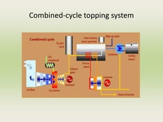
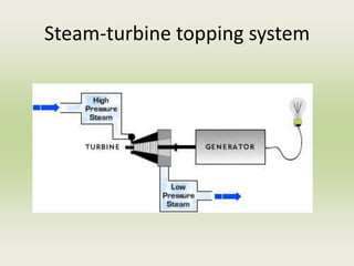
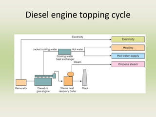
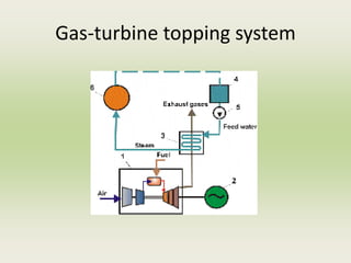
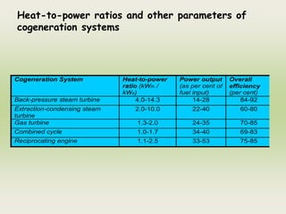
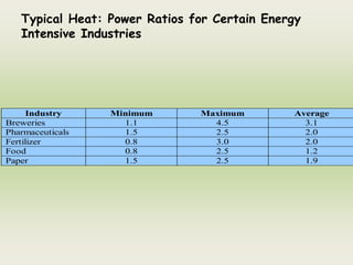
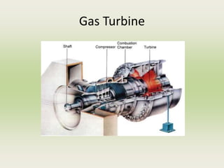
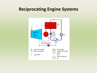
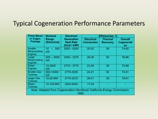
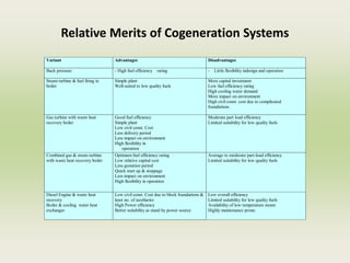
SlideShare a Scribd company logo
Energy Audit & Management
Cogeneration & Waste Heat Recovery : Unit 6
Outline
• Cogeneration
– Need
– Applications
– Advantages
– Classification
– The cogeneration design process
• Waste heat recovery
– Classification and application
– Potential for waste-heat recovery in Industry
– Commercial WHR devices
– Saving potential
• CDM projects and carbon credit calculations
DG set system
Syllabus
Diesel Generating system
Factors affecting selection
Energy performance assessment of diesel conservation
avenues
How Diesel Cycle works ?
A.C. Generator Controls
Diesel Engine Load
Accessories
Excitation Control
Fuel Control
Foundation
Fig-9.2 DG Set System
A DG set should be considered as a system
Specific fuel consumption
• The specific fuel consumption has
come down from a value of 220
g/kWh in the 1970s to a value
around 160 g/kWh in present times.
Slow speed diesel engine, with its flat
fuel consumption curve over a wide
load range (50%-100%), compares
very favourably over other prime
movers such as medium speed
diesel engine,
With high efficiency turbochargers, it
is possible to use an exhaust gas
driven turbine generator to further
increase the engine rated output.
Turbocharger
Advantages of adopting Diesel Power
Plants are:
• Low installation cost
• Short delivery periods and installation period
• Higher efficiency (as high as 43 -45 %)
• More efficient plant performance under part loads
• Suitable for different type of fuels such as low
sulphur
– heavy stock and heavy fuel oil in case of large
capacities.
• Minimum cooling water requirements,
• Adopted with air cooled heat exchanger in areas
• where water is not available
• Short start up time
Altitude and Intake Temperature Corrections
Correction Factors For Engine Output
Altitude Correction Temperature Correction
Altitude
Meters over
MSL
Non Super
Charged
Super Charged Intake oC
Correction
Factor
610 0.980 0.980 32 1.000
915 0.935 0.950 35 0.986
1220 0.895 0.915 38 0.974
1525 0.855 0.882 41 0.962
1830 0.820 0.850 43 0.950
2130 0.780 0.820 46 0.937
2450 0.745 0.790 49 0.925
2750 0.712 0.765 52 0.913
3050 0.680 0.740 54 0.900
3660 0.612 0.685
Derating due to Air Inter Cooler Water Inlet
Temperature
Water
Temperature oC
Flow % Derating %
25 100 0
30 125 3
35 166 5
40 166 8
Power Factor:
The load power factor is entirely dependent on
the load. The A.C. generator is designed for
the power factor of 0.8 lag as specified by
standards.
Lower power factor demands higher excitation
currents and results in increased losses. Over
sizing A.C. generators for operation at lower
power factors results in lower operating
efficiency and higher costs.
- Unbalanced Load:
Unbalanced loads on A.C. generator leads to unbalanced
set of voltages and additional heating in A.C. generator.
Hence, the load on the A.C. generators should be
balanced as far as possible.
Transient Loading:
On many occasions to contain transient voltage dip
arising due to transient load application, a specially
designed generator may have to be selected.
Energy Balance
& Waste Heat Recovery in DG Sets
A typical energy balance in a DG set indicates
following break-up:
Input :100% Thermal Energy
Outputs :35% Electrical Output
: 4% Alternator Losses
:33% Stack Loss through Flue Gases
:24% Coolant Losses
: 4% Radiation Losses
Typical Format for DG Set Monitoring
DG
Set
No.
Electricity
Generating
Capacity
(Site), kW
Derated
Electricity
Generating
Capacity, kW
Type of
Fuel
used
Average
Load as %
of Derated
Capacity
Specific
Fuel Cons.
Lit/kWh
Specific
Lube Oil
Cons.
Lit/kWh
1. 480 300 LDO 89 0.335 0.007
2. 480 300 LDO 110 0.334 0.024
3. 292 230 LDO 84 0.356 0.006
4. 200 160 HSD 89 0.325 0.003
5. 200 160 HSD 106 0.338 0.003
18. 880 750 LDO 78 0.345 0.007
19. 800 640 HSD 74 0.324 0.002
Energy Saving Measures for DG Sets
 Ensure steady load conditions on the DG set, and provide
cold, dust free air at intake
 Improve air filtration.
 Ensure fuel oil storage, handling and preparation as per
manufacturers’ guidelines/oil company data.
 Calibrate fuel injection pumps frequently.
 Ensure compliance with maintenance checklist.
 Ensure steady load conditions, avoiding fluctuations,
imbalance in phases, harmonic loads.
 For base load operation, consider waste heat recovery
system steam generation or vapour absorption system
adoption.
 Consider parallel operation among the DG sets for
improved loading .
 Carryout regular field trials to monitor DG set
performance, and maintenance planning as per
requirements.
Cogeneration
Need
Cogeneration
Applications
Cogeneration
Advantages
Cogeneration
Classifications
Cogeneration
The Design Process
Waste Heat Recovery
Classification and Applications
Waste Heat Recovery
Potential of Heat Recovery in Industry
Waste Heat Recovery
Commercial Devices
Waste Heat Recovery
Saving Potentials
CDM Projects
Energy Efficient Technologies
Maximum Demand
MD controller
Automatic Power Factor Controllers
Energy Efficient Motors
Design changes
Table 10.1 Watt Loss Area and Efficiency Improvement
{PRIVATE}Watts
Loss Area
Efficiency Improvement
1. Iron Use of thinner gauge, lower loss core steel reduces eddy current
losses. Longer core adds more steel to the design, which reduces
losses due to lower operating flux densities.
2. Stator I 2
R Use of more copper and larger conductors increases cross sectional
area of stator windings. This lowers resistance (R) of the windings
and reduces losses due to current flow (I).
3. Rotor I 2
R Use of larger rotor conductor bars increases size of cross section,
lowering conductor resistance (R) and losses due to current flow (I).
4. Friction & Windage Use of low loss fan design reduces losses due to air movement.
5. Stray Load Loss Use of optimised design and strict quality control procedures
minimizes stray load losses.
Technical aspects of Energy Efficient
Motors
• Energy-efficient motors last longer, and may require less
maintenance. At lower temperatures, bearing grease lasts longer;
required time between re-greasing increases. Lower temperatures
translate to long lasting insulation. Generally, motor life doubles
for each 10°C reduction in operating temperature.
• Electrical power problems, especially poor incoming power quality
can affect the operation of energy-efficient motors.
• Speed control is crucial in some applications. In polyphase
induction motors, slip is a measure of motor winding losses. The
lower the slip, the higher the efficiency. Less slippage in energy
efficient motors results in speeds about 1% faster than in
standard counterparts.
• Starting torque for efficient motors may be lower than for
standard motors. Facility managers should be careful when
applying efficient motors to high torque applications.
Soft Starters
Characteristics
Variable Frequency Drives
Motors connected to VFD provide variable speed
mechanical output with high efficiency. These
devices are capable of up to a 9:1 speed reduction
ratio (11 percent of full speed), and a 3:1 speed
increase (300 percent of full speed).
Variable Torque Vs. Constant Torque
• Variable torque loads include centrifugal pumps
and fans, which make up the majority of HVAC
applications.
• Constant torque loads include vibrating conveyors,
punch presses, rock crushers, machine tools, and
other applications where the drive follows a
constant V/Hz ratio.
Typical full-load efficiencies are 95% and higher
Fluid coupling
Energy Efficient Transformers
1600 kVA Amorphous
Core Transformer
Electronic Ballast
Energy Efficient Lighting Controls
• Occupancy Sensors
• Timed Based Control
• Daylight Linked Control
• Localized Switching
COGENERATION
Need for cogeneration
Principle of Cogeneration
Through separate heat and power route
primary energy input in power plant will be 60 units (24/0.40)
If a separate boiler is used for steam generation then the fuel input
to boiler will be 40 units (34/0.85).
If the plant had cogeneration then the fuel input will be only 68
units (24+34)/0.85 to meet both electrical and thermal energy
requirements
It can be observed that the losses, which were 42 units in the case
of, separate heat and power has reduced to 10 units in cogeneration
mode
Along with the saving of fossil fuels, cogeneration also allows to
reduce the emission of greenhouse gases (particularly CO2
emission). The production of electricity being on-site, the burden on
the utility network is reduced and the transmission line losses
eliminated
Technical Options for Cogeneration
• Cogeneration technologies that have been widely
commercialized include
– extraction/back pressure steam turbines
– gas turbine with heat recovery boiler (with or without
bottoming steam turbine)
– reciprocating engines with heat recovery boiler
Steam turbine cogeneration systems
Steam turbine cogeneration features
• The choice between backpressure turbine and extraction-
condensing turbine depends mainly on the quantities of power
and heat, quality of heat, and economic factors
• option for using a wide variety of conventional as well as
alternative fuels such as coal, natural gas, fuel oil and biomass
• power generation efficiency of the cycle may be sacrificed to
some extent in order to optimize heat supply
• In backpressure cogeneration plants, there is no need for large
cooling towers
• Steam turbines are mostly used where the demand for
electricity is greater than one MW up to a few hundreds of MW
• Due to the system inertia, their operation is not suitable for
sites with intermittent energy demand
Gas turbine cogeneration systems
Gas turbine cogeneration features
• natural gas is most commonly used; other fuels such as light fuel
oil or diesel can also be employed
• The typical range of gas turbines varies from a fraction of a
MW to around 100 MW
• the gestation period for developing a project is shorter and the
equipment can be delivered in a modular manner
• Gas turbine has a short start-up time and provides the
flexibility of intermittent operation
• If the heat output is less than that required by the user, it is
possible to have supplementary natural gas firing
• if more power is required at the site, it is possible to adopt a
combined cycle that is a combination of gas turbine and steam
turbine cogeneration
Reciprocating engine cogeneration systems
Reciprocating engine cogeneration features
• high power generation efficiencies in comparison with other prime
movers
• There are two sources of heat for recovery: exhaust gas at high
temperature and engine jacket cooling water system at low temperature
• more popular with smaller energy consuming facilities, particularly those
having a greater need for electricity than thermal energy
• diesel has been the most common fuel in the past, the prime movers can
also operate with heavy fuel oil or natural gas
• ideal for intermittent operation and their performance is not as
sensitive to the changes in ambient temperatures as the gas turbines
• Though the initial investment on these machines is low, their operating
and maintenance costs are high due to high wear and tear
Classification of Cogeneration Systems
• A cogeneration system can be classified as either a
topping or a bottoming cycle on the basis of the
sequence of energy use
• In a topping cycle, the fuel supplied is used to first
produce power and then thermal energy, which is the by-
product of the cycle and is used to satisfy process heat
or other thermal requirements
• In a bottoming cycle, the primary fuel produces high
temperature thermal energy and the heat rejected from
the process is used to generate power through a
recovery boiler and a turbine generator
Combined-cycle topping system
Steam-turbine topping system
Diesel engine topping cycle
Gas-turbine topping system
Bottoming Cycle
Factors Influencing Cogeneration Choice
Base electrical load matching
• the cogeneration plant is sized to meet the minimum
electricity demand of the site based on the historical
demand curve
• rest of the needed power is purchased from the utility
grid
• thermal energy requirement of the site could be met by
the cogeneration system alone or by additional boilers
• If the thermal energy generated with the base electrical
load exceeds the plant’s demand and if the situation
permits, excess thermal energy can be exported to
neighbouring customers
Base thermal load matching
• the cogeneration system is sized to supply the minimum
thermal energy requirement of the site. Stand-by boilers
or burners are operated during periods when the demand
for heat is higher
• The prime mover installed operates at full load at all
times
• If the electricity demand of the site exceeds that which
can be provided by the prime mover, then the remaining
amount can be purchased from the grid
• Likewise, if local laws permit, the excess electricity can
be sold to the power utility
Electrical load matching
• the facility is totally independent of the power utility grid
• All the power requirements of the site, including the reserves
needed during scheduled and unscheduled maintenance, are to be
taken into account while sizing the system
• This is also referred to as a “stand-alone” system
• If the thermal energy demand of the site is higher than that
generated by the cogeneration system, auxiliary boilers are used
• On the other hand, when the thermal energy demand is low, some
thermal energy is wasted
• If there is a possibility, excess thermal energy can be exported to
neighbouring facilities
Thermal load matching
• The cogeneration system is designed to meet
the thermal energy requirement of the site at
any time
• The prime movers are operated following the
thermal demand
• During the period when the electricity
demand exceeds the generation capacity, the
deficit can be compensated by power
purchased from the grid
• Similarly, if the local legislation permits,
electricity produced in excess at any time
may be sold to the utility
Important Technical Parameters for
Cogeneration
Heat-to-power ratio
• Heat-to-power ratio is one of the most important technical
parameters influencing the selection of the type of cogeneration
system
• The heat-to-power ratio of a facility should match with the
characteristics of the cogeneration system to be installed
• It is defined as the ratio of thermal energy to electricity
required by the energy consuming facility
• Though it can be expressed in different units such as Btu/kWh,
kcal/kWh, lb./hr/kW, etc., here it is presented on the basis of
the same energy unit (kW)
• The steam turbine cogeneration system can offer a large range
of heat-to- power ratios.
• The proportions of heat and power needed (heat: power ratio)
vary from site to site, so the type of plant must be selected
carefully and appropriate operating schemes must be
established to match demands as closely as possible
Heat-to-power ratios and other parameters of
cogeneration systems
Cogeneration System Heat-to-power
ratio (kWth /
kWe)
Power output
(as per cent of
fuel input)
Overall
efficiency
(per cent)
Back-pressure steam turbine 4.0-14.3 14-28 84-92
Extraction-condensing steam
turbine
2.0-10.0 22-40 60-80
Gas turbine 1.3-2.0 24-35 70-85
Combined cycle 1.0-1.7 34-40 69-83
Reciprocating engine 1.1-2.5 33-53 75-85
Typical Heat: Power Ratios for Certain Energy
Intensive Industries
Industry Minimum Maximum Average
Breweries 1.1 4.5 3.1
Pharmaceuticals 1.5 2.5 2.0
Fertilizer 0.8 3.0 2.0
Food 0.8 2.5 1.2
Paper 1.5 2.5 1.9
Cogeneration is likely to be most attractive if
• The demand for both steam and power is
balanced i.e. consistent with the range of
steam: power output ratios that can be
obtained from a suitable cogeneration plant.
• A single plant or group of plants has
sufficient demand for steam and power to
permit economies of scale to be achieved.
• Peaks and troughs in demand can be managed
or, in the case of electricity, adequate backup
supplies can be obtained from the utility
company
Quality of thermal energy needed
• The quality of thermal energy required
(temperature and pressure) also determines
the type of cogeneration system
• For a sugar mill needing thermal energy at
about 120°C, a topping cycle cogeneration
system can meet the heat demand
• On the other hand, for a cement plant
requiring thermal energy at about 1450°C, a
bottoming cycle cogeneration system can
meet both high quality thermal energy and
electricity demands of the plant
Load patterns
Fuels available
• Depending on the availability of fuels, some potential
cogeneration systems may have to be rejected
• The availability of cheap fuels or waste products that
can be used as fuels at a site is one of the major
factors in the technical consideration because it
determines the competitiveness of the cogeneration
system.
• A rice mill needs mechanical power for milling and
heat for paddy drying.
• If a cogeneration system were considered, the steam
turbine system would be the first priority because it
can use the rice husk as the fuel, which is available as
waste product from the mill.
System reliability
• Some energy consuming facilities require very
reliable power and/or heat
• for instance, a pulp and paper industry cannot
operate with a prolonged unavailability of
process steam
• In such instances, the cogeneration system to
be installed must be modular, i.e. it should
consist of more than one unit so that shut
down of a specific unit cannot seriously
affect the energy supply
Grid dependent system versus independent system
• A grid-dependent system has access to the grid to buy
or sell electricity
• The grid-independent system is also known as a “stand-
alone” system that meets all the energy demands of the
site
• It is obvious that for the same energy consuming
facility, the technical configuration of the cogeneration
system designed as a grid dependent system would be
different from that of a stand-alone system.
Retrofit versus new installation
• If the cogeneration system is installed as a retrofit,
the system must be designed so that the existing
energy conversion systems, such as boilers, can still
be used
• In such a circumstance, the options for cogeneration
system would depend on whether the system is a
retrofit or a new installation
Electricity buy-back
• The technical consideration of cogeneration system
must take into account whether the local regulations
permit electric utilities to buy electricity from the
cogenerators or not
• The size and type of cogeneration system could be
significantly different if one were to allow the export
of electricity to the grid
Local environmental regulation
• The local environmental regulations can limit the
choice of fuels to be used for the proposed
cogeneration systems
• If the local environmental regulations are stringent,
some available fuels cannot be considered because of
the high treatment cost of the polluted exhaust gas
and in some cases, the fuel itself
Prime Movers for Cogeneration
Steam Turbine
Back pressure Steam Turbine
Extraction condensing Steam Turbine
Gas Turbine
Reciprocating Engine Systems
Typical Cogeneration Performance Parameters
Efficiencies, %
Prime Mover
in Cogen.
Package
Nominal
Range
(Electrical)
Electrical
Generation
Heat Rate
(kCal / kWH
Electrical
Conversion
Thermal
Recovery
Overall
Cogenerati
on
Smaller
Reciprocating
Engines
10 – 500
kW
2650 - 6300 20-32 50 74-82
Larger
Reciprocating
Engines
500 – 3000
kW
2400 - 3275 26-36 50 76-86
Diesel
Engines
10-3000
kW
2770 - 3775 23-38 50 73-88
Smaller Gas
Turbines
800-10000
kW
2770-3525 24-31 50 74-81
Larger Gas
Turbines
10-20 MW 2770-3275 26-31 50 78-81
Steam
Turbines
10-100 MW 2520-5040 17-34 - -
Note: Adapted from Cogeneration Handbook California Energy Commission,
1982
Relative Merits of Cogeneration Systems
Variant Advantages Disadvantages
Back pressure - High fuel efficiency rating - Little flexibility indesign and operation
Steam turbine & fuel firing in
boiler
Simple plant
Well-suited to low quality fuels
More capital investment
Low fuel efficiency rating
High cooling water demand
More impact on environment
High civil const. cost due to complicated
foundations
Gas turbine with waste heat
recovery boiler
Good fuel efficiency
Simple plant
Low civil const. Cost
Less delivery period
Less impact on environment
High flexibility in
operation
Moderate part load efficiency
Limited suitability for low quality fuels
Combined gas & steam turbine
with waste heat recovery boiler
Optimum fuel efficiency rating
Low relative capital cost
Less gestation period
Quick start up & stoppage
Less impact on environment
High flexibility in operation
Average to moderate part-load efficiency
Limited suitability for low quality fuels
Diesel Engine & waste heat
recovery
Boiler & cooling water heat
exchanger
Low civil const. Cost due to block foundations &
least no. of auxiliaries
High Power efficiency
Better suitability as stand by power source
Low overall efficiency
Limited suitability for low quality fuels
Availability of low temperature steam
Highly maintenance prone.
Waste Heat Recovery (WHR)
8.1 Introduction
What is waste heat?
• Waste heat is heat, which is
generated in a process by way of fuel
combustion or chemical reaction, and
then “dumped” into the environment
even though it could still be reused
for some useful and economic
purpose.
Sources of Waste Heat
• Boilers
• Kilns
• Ovens
• Furnaces
• DG Sets
• Thermic Fluid Heaters
• Low temperature process streams
Factors determining WHR
• Heat Loss
Quality
Quantity
8.2 Classification and Application
Source Quality
Heat in flue gases. The higher the temperature,
the greater the potential value
for heat recovery
Heat in vapour streams. As above but when
condensed, latent heat also
recoverable.
Convective and radiant heat
lost from exterior of
equipment
Low grade – if collected may
be used for space heating or
air preheats.
Heat losses in cooling water. Low grade – useful gains if
heat is exchanged with
incoming fresh water.
Classification and Application
Source Quality
Heat losses in providing
chilled water or in the
disposal of chilled water.
a) High grade if it can be
utilized to reduce demand for
refrigeration.
b) Low grade if refrigeration
unit used as a form of heat
pump.
Heat stored in products
leaving the process
Quality depends upon
temperature.
Heat in gaseous and liquid
effluents leaving process.
Poor if heavily contaminated
and thus requiring alloy heat
exchanger.
High Temperature Heat Recovery
Types of Device Temperature, oC
Nickel refining furnace 1370 –1650
Aluminium refining furnace 650-760
Zinc refining furnace 760-1100
Copper reverberatory furnace 900-1100
Cement kiln (Dry process) 620- 730
Glass melting furnace 1000-1550
Medium Temperature Heat Recovery
Types of Device Temperature, oC
Steam boiler exhausts 230-480
Gas turbine exhausts 370-540
Reciprocating engine
exhausts
315-600
Heat treating furnaces 425 - 650
Catalytic crackers 425 - 650
Annealing furnace cooling
systems
425 - 650
Low Temperature Heat Recovery
Source Temperature, oC
Process steam condensate 55-88
Cooling water from:
Furnace doors 32-55
Annealing furnaces 66-230
Air compressors 27-50
Air conditioning and
refrigeration condensers
32–43
Benefits of WHR
• Direct benefits
• Indirect benefits
Reduction in Pollution
Reduction in equipment
sizes
Reduction in auxiliary
Energy consumption
Development of Waste Heat Recovery
System
• Understand the process
– Sources and uses of waste heat
– Upset conditions occurring in the plant due to heat recovery
– Availability of space
– Any other constraint, such as dew point occurring in an
equipment, etc.
• Economic evaluation of WHR System
Commercial WHR Devices
• Recuperator
• Regenerator
• Heat Wheel
• Heat Pipe
• Economiser
• Shell and tube heat exchanger
• Waste heat boiler
• Heat Pump
• Thermocompressor
• Direct contact heat exchanger
Recuperator
In a recuperator, heat exchange takes
place between the flue gases and the air
through metallic or ceramic walls. Duct or
tubes carry the air for combustion to be
pre-heated, the other side contains the
waste heat stream.
Metallic Radiation Recuperator
The radiation recuperator
gets its name from the fact
that a substantial portion of
the heat transfer from the
hot gases to the surface of
the inner tube takes place by
radiative heat transfer
Figure 8.2 Metallic Radiation Recuperator
Convective Recuperator
The hot gases are carried through
a number of parallel small
diameter tubes, while the
incoming air to be heated enters a
shell surrounding the tubes and
passes over the hot tubes one or
more times in a direction normal
to their axes.
Convective Radiative Recuperator
For maximum effectiveness of
heat transfer, combinations of
radiation and convective
designs are used, with the
high-temperature radiation
recuperator being first followed
by convection type.
Ceramic Recuperator
• In order to overcome the temperature limitation of
metallic recuperators which is about 1000oC on the
gas side, ceramic tube recuperators have been
developed.
• The materials of ceramic recuperators allow
operation on the gas side up to 1300 oC and on the
preheated air side up to 850 oC.
Regenerator
The Regeneration which is
preferable for large capacities has
been very widely used in glass and
steel melting furnaces.
Important relations exist between
the size of the regenerator, time
between reversals, thickness of
brick, conductivity of brick and heat
storage ratio of the brick.
Heat Wheels
Widely used in low to
medium temperature waste
heat recovery systems.
A disk rotates
between two side-by-side
ducts: one a cold gas duct,
the other a hot gas duct.
As the disk slowly rotates, sensible heat
(moisture that contains latent heat) is
transferred to the disk by the hot air
and, as the disk rotates, from the disk to
the cold air.
Heat Pipe
Heat pipe is a thermal energy absorbing and transferring system and have
no moving parts and hence require minimum maintenance.
wall
Economiser
Widely used in a
boiler system
1. To pre-heat the
boiler feed
water.
2. To pre-heat the
combustion air.
by utilizing the heat
in the flue gas.
Shell and Tube Heat Exchanger
When the medium containing waste heat is a liquid or a vapor which heats another
liquid, then the shell and tube heat exchanger must be used since both paths must
be sealed to contain the pressures of their respective fluids.
Plate Heat Exchanger
The cost of heat exchange surfaces is a major factor when the temperature differences
are not large. In such case this is used. Hot liquid passing through a bottom port in the
head is permitted to pass upwards between every second plate while cold liquid at the
top of the head is permitted to pass downwards between the odd plates. When the
directions of hot & cold fluids are opposite, the arrangement is described as counter
current
Figure 8.10 Plate Heat Exchanger
Waste Heat Boilers
Waste heat boilers are ordinarily water tube
boilers in which the hot exhaust gases from gas
turbines, incinerators, etc., pass over a number
of parallel tubes containing water. The water is
vaporized in the tubes and collected in a steam
drum from which it is drawn off for use as
heating or processing steam
Heat Pumps
Heat pump processes :
1. In the evaporator the heat is extracted from the heat
source to boil the circulating substance;
2. The circulating substance is compressed by the compressor,
raising its pressure and temperature; The low temperature
vapor is compressed by a compressor, which requires
external work. The work done on the vapor raises its
pressure and temperature to a level where its energy
becomes available for use
3. The heat is delivered to the condenser;
4. The pressure of the circulating substance (working fluid) is
reduced back to the evaporator condition in the throttling
valve, where the cycle repeats.
The heat pump was developed as a space heating system
The heat pumps have the ability to upgrade heat to a value more than twice that
of the energy consumed by the device
Thermocompressor
SUCTION
STEAM L.P.
Discharge
Steam
M.P
Motive
Steam
H.P
The thermocompressor is a simple equipment with a nozzle where HP steam is
accelerated into a high velocity fluid. This entrains the LP steam by momentum transfer
and then recompresses in a divergent venturi.
Direct Contact Heat Exchanger
COLD
WATER
IN
VENT
L.P.
STEAM
HOT
WATER
Low pressure steam may also be
used to preheat the feed water or
some other fluid where miscibility
is acceptable. This principle is used
here.

More Related Content

Similar to Unit_No_6.pptx

Energy Efficient Appliances
Energy Efficient AppliancesEnergy Efficient Appliances
Energy Efficient AppliancesVijay Sharma
 
GrameenPhone
GrameenPhoneGrameenPhone
21 GSR.pptx
21 GSR.pptx21 GSR.pptx
21 GSR.pptx
chandu052041
 
2010 Energy Audit Presentation
2010 Energy Audit Presentation2010 Energy Audit Presentation
2010 Energy Audit Presentationcbocci
 
2010 Energy Presentation
2010 Energy Presentation2010 Energy Presentation
2010 Energy Presentation
TinaAllen
 
2010 Energy Presentation
2010 Energy Presentation2010 Energy Presentation
2010 Energy Presentationguest9176b3
 
Sym Opti Motor Energy By Tahir Saleem
Sym Opti Motor Energy By Tahir SaleemSym Opti Motor Energy By Tahir Saleem
Sym Opti Motor Energy By Tahir Saleem
IEEEP Karachi
 
Thermal power generator
 Thermal power generator Thermal power generator
Thermal power generator
Andre Draayer
 
Cogeneration CHP Combined Heat & Power Power Plant
Cogeneration  CHP Combined Heat & Power Power PlantCogeneration  CHP Combined Heat & Power Power Plant
Cogeneration CHP Combined Heat & Power Power Plant
KESHAV
 
Virtual pipelines 201: Industrial CNG Applications Beyond the Pipeline
Virtual pipelines 201: Industrial CNG Applications Beyond the PipelineVirtual pipelines 201: Industrial CNG Applications Beyond the Pipeline
Virtual pipelines 201: Industrial CNG Applications Beyond the Pipeline
Clean Energy Compression (formerly IMW Industries)
 
Talk on energy efficiency by ajai arora
Talk on energy efficiency  by ajai aroraTalk on energy efficiency  by ajai arora
Talk on energy efficiency by ajai arora
Ratan Kuber
 
Energy Conservation Techniques For Industries
Energy Conservation Techniques For IndustriesEnergy Conservation Techniques For Industries
Energy Conservation Techniques For IndustriesShakti Prasad Ghadei
 
Energy audit & conservation studies for industries
Energy audit & conservation studies for industriesEnergy audit & conservation studies for industries
Energy audit & conservation studies for industries
ravindradatar
 
Ntpc business strategy
Ntpc business strategyNtpc business strategy
Ntpc business strategy
Shiva Prashanth Kasina
 
DISTRIBUTED GENERATION & POWER QUALITY
DISTRIBUTED GENERATION & POWER QUALITY DISTRIBUTED GENERATION & POWER QUALITY
DISTRIBUTED GENERATION & POWER QUALITY
Power System Operation
 
Planning & Operating Electricty Network with Renewable Generation-5
Planning & Operating Electricty Network with Renewable Generation-5Planning & Operating Electricty Network with Renewable Generation-5
Planning & Operating Electricty Network with Renewable Generation-5
Power System Operation
 
Cogeneration
CogenerationCogeneration
Cogeneration
ChristusJeyaSinghV
 
48_25785_MM525_2018_1__2_1_Marine Gas turbine LECTURES.pdf
48_25785_MM525_2018_1__2_1_Marine Gas turbine LECTURES.pdf48_25785_MM525_2018_1__2_1_Marine Gas turbine LECTURES.pdf
48_25785_MM525_2018_1__2_1_Marine Gas turbine LECTURES.pdf
yannik8
 
Technical partners for energy conservation
Technical partners for energy conservationTechnical partners for energy conservation
Technical partners for energy conservationsachindesai055
 

Similar to Unit_No_6.pptx (20)

Energy Efficient Appliances
Energy Efficient AppliancesEnergy Efficient Appliances
Energy Efficient Appliances
 
GrameenPhone
GrameenPhoneGrameenPhone
GrameenPhone
 
21 GSR.pptx
21 GSR.pptx21 GSR.pptx
21 GSR.pptx
 
Presentation 2
Presentation 2Presentation 2
Presentation 2
 
2010 Energy Audit Presentation
2010 Energy Audit Presentation2010 Energy Audit Presentation
2010 Energy Audit Presentation
 
2010 Energy Presentation
2010 Energy Presentation2010 Energy Presentation
2010 Energy Presentation
 
2010 Energy Presentation
2010 Energy Presentation2010 Energy Presentation
2010 Energy Presentation
 
Sym Opti Motor Energy By Tahir Saleem
Sym Opti Motor Energy By Tahir SaleemSym Opti Motor Energy By Tahir Saleem
Sym Opti Motor Energy By Tahir Saleem
 
Thermal power generator
 Thermal power generator Thermal power generator
Thermal power generator
 
Cogeneration CHP Combined Heat & Power Power Plant
Cogeneration  CHP Combined Heat & Power Power PlantCogeneration  CHP Combined Heat & Power Power Plant
Cogeneration CHP Combined Heat & Power Power Plant
 
Virtual pipelines 201: Industrial CNG Applications Beyond the Pipeline
Virtual pipelines 201: Industrial CNG Applications Beyond the PipelineVirtual pipelines 201: Industrial CNG Applications Beyond the Pipeline
Virtual pipelines 201: Industrial CNG Applications Beyond the Pipeline
 
Talk on energy efficiency by ajai arora
Talk on energy efficiency  by ajai aroraTalk on energy efficiency  by ajai arora
Talk on energy efficiency by ajai arora
 
Energy Conservation Techniques For Industries
Energy Conservation Techniques For IndustriesEnergy Conservation Techniques For Industries
Energy Conservation Techniques For Industries
 
Energy audit & conservation studies for industries
Energy audit & conservation studies for industriesEnergy audit & conservation studies for industries
Energy audit & conservation studies for industries
 
Ntpc business strategy
Ntpc business strategyNtpc business strategy
Ntpc business strategy
 
DISTRIBUTED GENERATION & POWER QUALITY
DISTRIBUTED GENERATION & POWER QUALITY DISTRIBUTED GENERATION & POWER QUALITY
DISTRIBUTED GENERATION & POWER QUALITY
 
Planning & Operating Electricty Network with Renewable Generation-5
Planning & Operating Electricty Network with Renewable Generation-5Planning & Operating Electricty Network with Renewable Generation-5
Planning & Operating Electricty Network with Renewable Generation-5
 
Cogeneration
CogenerationCogeneration
Cogeneration
 
48_25785_MM525_2018_1__2_1_Marine Gas turbine LECTURES.pdf
48_25785_MM525_2018_1__2_1_Marine Gas turbine LECTURES.pdf48_25785_MM525_2018_1__2_1_Marine Gas turbine LECTURES.pdf
48_25785_MM525_2018_1__2_1_Marine Gas turbine LECTURES.pdf
 
Technical partners for energy conservation
Technical partners for energy conservationTechnical partners for energy conservation
Technical partners for energy conservation
 

Recently uploaded

WATER CRISIS and its solutions-pptx 1234
WATER CRISIS and its solutions-pptx 1234WATER CRISIS and its solutions-pptx 1234
WATER CRISIS and its solutions-pptx 1234
AafreenAbuthahir2
 
English lab ppt no titlespecENG PPTt.pdf
English lab ppt no titlespecENG PPTt.pdfEnglish lab ppt no titlespecENG PPTt.pdf
English lab ppt no titlespecENG PPTt.pdf
BrazilAccount1
 
RAT: Retrieval Augmented Thoughts Elicit Context-Aware Reasoning in Long-Hori...
RAT: Retrieval Augmented Thoughts Elicit Context-Aware Reasoning in Long-Hori...RAT: Retrieval Augmented Thoughts Elicit Context-Aware Reasoning in Long-Hori...
RAT: Retrieval Augmented Thoughts Elicit Context-Aware Reasoning in Long-Hori...
thanhdowork
 
一比一原版(UofT毕业证)多伦多大学毕业证成绩单如何办理
一比一原版(UofT毕业证)多伦多大学毕业证成绩单如何办理一比一原版(UofT毕业证)多伦多大学毕业证成绩单如何办理
一比一原版(UofT毕业证)多伦多大学毕业证成绩单如何办理
ydteq
 
Industrial Training at Shahjalal Fertilizer Company Limited (SFCL)
Industrial Training at Shahjalal Fertilizer Company Limited (SFCL)Industrial Training at Shahjalal Fertilizer Company Limited (SFCL)
Industrial Training at Shahjalal Fertilizer Company Limited (SFCL)
MdTanvirMahtab2
 
space technology lecture notes on satellite
space technology lecture notes on satellitespace technology lecture notes on satellite
space technology lecture notes on satellite
ongomchris
 
Fundamentals of Electric Drives and its applications.pptx
Fundamentals of Electric Drives and its applications.pptxFundamentals of Electric Drives and its applications.pptx
Fundamentals of Electric Drives and its applications.pptx
manasideore6
 
J.Yang, ICLR 2024, MLILAB, KAIST AI.pdf
J.Yang,  ICLR 2024, MLILAB, KAIST AI.pdfJ.Yang,  ICLR 2024, MLILAB, KAIST AI.pdf
J.Yang, ICLR 2024, MLILAB, KAIST AI.pdf
MLILAB
 
Planning Of Procurement o different goods and services
Planning Of Procurement o different goods and servicesPlanning Of Procurement o different goods and services
Planning Of Procurement o different goods and services
JoytuBarua2
 
Gen AI Study Jams _ For the GDSC Leads in India.pdf
Gen AI Study Jams _ For the GDSC Leads in India.pdfGen AI Study Jams _ For the GDSC Leads in India.pdf
Gen AI Study Jams _ For the GDSC Leads in India.pdf
gdsczhcet
 
weather web application report.pdf
weather web application report.pdfweather web application report.pdf
weather web application report.pdf
Pratik Pawar
 
Investor-Presentation-Q1FY2024 investor presentation document.pptx
Investor-Presentation-Q1FY2024 investor presentation document.pptxInvestor-Presentation-Q1FY2024 investor presentation document.pptx
Investor-Presentation-Q1FY2024 investor presentation document.pptx
AmarGB2
 
一比一原版(SFU毕业证)西蒙菲莎大学毕业证成绩单如何办理
一比一原版(SFU毕业证)西蒙菲莎大学毕业证成绩单如何办理一比一原版(SFU毕业证)西蒙菲莎大学毕业证成绩单如何办理
一比一原版(SFU毕业证)西蒙菲莎大学毕业证成绩单如何办理
bakpo1
 
CFD Simulation of By-pass Flow in a HRSG module by R&R Consult.pptx
CFD Simulation of By-pass Flow in a HRSG module by R&R Consult.pptxCFD Simulation of By-pass Flow in a HRSG module by R&R Consult.pptx
CFD Simulation of By-pass Flow in a HRSG module by R&R Consult.pptx
R&R Consult
 
The Benefits and Techniques of Trenchless Pipe Repair.pdf
The Benefits and Techniques of Trenchless Pipe Repair.pdfThe Benefits and Techniques of Trenchless Pipe Repair.pdf
The Benefits and Techniques of Trenchless Pipe Repair.pdf
Pipe Restoration Solutions
 
ethical hacking in wireless-hacking1.ppt
ethical hacking in wireless-hacking1.pptethical hacking in wireless-hacking1.ppt
ethical hacking in wireless-hacking1.ppt
Jayaprasanna4
 
ML for identifying fraud using open blockchain data.pptx
ML for identifying fraud using open blockchain data.pptxML for identifying fraud using open blockchain data.pptx
ML for identifying fraud using open blockchain data.pptx
Vijay Dialani, PhD
 
NO1 Uk best vashikaran specialist in delhi vashikaran baba near me online vas...
NO1 Uk best vashikaran specialist in delhi vashikaran baba near me online vas...NO1 Uk best vashikaran specialist in delhi vashikaran baba near me online vas...
NO1 Uk best vashikaran specialist in delhi vashikaran baba near me online vas...
Amil Baba Dawood bangali
 
Hierarchical Digital Twin of a Naval Power System
Hierarchical Digital Twin of a Naval Power SystemHierarchical Digital Twin of a Naval Power System
Hierarchical Digital Twin of a Naval Power System
Kerry Sado
 
Design and Analysis of Algorithms-DP,Backtracking,Graphs,B&B
Design and Analysis of Algorithms-DP,Backtracking,Graphs,B&BDesign and Analysis of Algorithms-DP,Backtracking,Graphs,B&B
Design and Analysis of Algorithms-DP,Backtracking,Graphs,B&B
Sreedhar Chowdam
 

Recently uploaded (20)

WATER CRISIS and its solutions-pptx 1234
WATER CRISIS and its solutions-pptx 1234WATER CRISIS and its solutions-pptx 1234
WATER CRISIS and its solutions-pptx 1234
 
English lab ppt no titlespecENG PPTt.pdf
English lab ppt no titlespecENG PPTt.pdfEnglish lab ppt no titlespecENG PPTt.pdf
English lab ppt no titlespecENG PPTt.pdf
 
RAT: Retrieval Augmented Thoughts Elicit Context-Aware Reasoning in Long-Hori...
RAT: Retrieval Augmented Thoughts Elicit Context-Aware Reasoning in Long-Hori...RAT: Retrieval Augmented Thoughts Elicit Context-Aware Reasoning in Long-Hori...
RAT: Retrieval Augmented Thoughts Elicit Context-Aware Reasoning in Long-Hori...
 
一比一原版(UofT毕业证)多伦多大学毕业证成绩单如何办理
一比一原版(UofT毕业证)多伦多大学毕业证成绩单如何办理一比一原版(UofT毕业证)多伦多大学毕业证成绩单如何办理
一比一原版(UofT毕业证)多伦多大学毕业证成绩单如何办理
 
Industrial Training at Shahjalal Fertilizer Company Limited (SFCL)
Industrial Training at Shahjalal Fertilizer Company Limited (SFCL)Industrial Training at Shahjalal Fertilizer Company Limited (SFCL)
Industrial Training at Shahjalal Fertilizer Company Limited (SFCL)
 
space technology lecture notes on satellite
space technology lecture notes on satellitespace technology lecture notes on satellite
space technology lecture notes on satellite
 
Fundamentals of Electric Drives and its applications.pptx
Fundamentals of Electric Drives and its applications.pptxFundamentals of Electric Drives and its applications.pptx
Fundamentals of Electric Drives and its applications.pptx
 
J.Yang, ICLR 2024, MLILAB, KAIST AI.pdf
J.Yang,  ICLR 2024, MLILAB, KAIST AI.pdfJ.Yang,  ICLR 2024, MLILAB, KAIST AI.pdf
J.Yang, ICLR 2024, MLILAB, KAIST AI.pdf
 
Planning Of Procurement o different goods and services
Planning Of Procurement o different goods and servicesPlanning Of Procurement o different goods and services
Planning Of Procurement o different goods and services
 
Gen AI Study Jams _ For the GDSC Leads in India.pdf
Gen AI Study Jams _ For the GDSC Leads in India.pdfGen AI Study Jams _ For the GDSC Leads in India.pdf
Gen AI Study Jams _ For the GDSC Leads in India.pdf
 
weather web application report.pdf
weather web application report.pdfweather web application report.pdf
weather web application report.pdf
 
Investor-Presentation-Q1FY2024 investor presentation document.pptx
Investor-Presentation-Q1FY2024 investor presentation document.pptxInvestor-Presentation-Q1FY2024 investor presentation document.pptx
Investor-Presentation-Q1FY2024 investor presentation document.pptx
 
一比一原版(SFU毕业证)西蒙菲莎大学毕业证成绩单如何办理
一比一原版(SFU毕业证)西蒙菲莎大学毕业证成绩单如何办理一比一原版(SFU毕业证)西蒙菲莎大学毕业证成绩单如何办理
一比一原版(SFU毕业证)西蒙菲莎大学毕业证成绩单如何办理
 
CFD Simulation of By-pass Flow in a HRSG module by R&R Consult.pptx
CFD Simulation of By-pass Flow in a HRSG module by R&R Consult.pptxCFD Simulation of By-pass Flow in a HRSG module by R&R Consult.pptx
CFD Simulation of By-pass Flow in a HRSG module by R&R Consult.pptx
 
The Benefits and Techniques of Trenchless Pipe Repair.pdf
The Benefits and Techniques of Trenchless Pipe Repair.pdfThe Benefits and Techniques of Trenchless Pipe Repair.pdf
The Benefits and Techniques of Trenchless Pipe Repair.pdf
 
ethical hacking in wireless-hacking1.ppt
ethical hacking in wireless-hacking1.pptethical hacking in wireless-hacking1.ppt
ethical hacking in wireless-hacking1.ppt
 
ML for identifying fraud using open blockchain data.pptx
ML for identifying fraud using open blockchain data.pptxML for identifying fraud using open blockchain data.pptx
ML for identifying fraud using open blockchain data.pptx
 
NO1 Uk best vashikaran specialist in delhi vashikaran baba near me online vas...
NO1 Uk best vashikaran specialist in delhi vashikaran baba near me online vas...NO1 Uk best vashikaran specialist in delhi vashikaran baba near me online vas...
NO1 Uk best vashikaran specialist in delhi vashikaran baba near me online vas...
 
Hierarchical Digital Twin of a Naval Power System
Hierarchical Digital Twin of a Naval Power SystemHierarchical Digital Twin of a Naval Power System
Hierarchical Digital Twin of a Naval Power System
 
Design and Analysis of Algorithms-DP,Backtracking,Graphs,B&B
Design and Analysis of Algorithms-DP,Backtracking,Graphs,B&BDesign and Analysis of Algorithms-DP,Backtracking,Graphs,B&B
Design and Analysis of Algorithms-DP,Backtracking,Graphs,B&B
 

Unit_No_6.pptx

  • 1. Energy Audit & Management Cogeneration & Waste Heat Recovery : Unit 6
  • 2. Outline • Cogeneration – Need – Applications – Advantages – Classification – The cogeneration design process • Waste heat recovery – Classification and application – Potential for waste-heat recovery in Industry – Commercial WHR devices – Saving potential • CDM projects and carbon credit calculations
  • 3. DG set system Syllabus Diesel Generating system Factors affecting selection Energy performance assessment of diesel conservation avenues
  • 5. A.C. Generator Controls Diesel Engine Load Accessories Excitation Control Fuel Control Foundation Fig-9.2 DG Set System A DG set should be considered as a system
  • 6. Specific fuel consumption • The specific fuel consumption has come down from a value of 220 g/kWh in the 1970s to a value around 160 g/kWh in present times. Slow speed diesel engine, with its flat fuel consumption curve over a wide load range (50%-100%), compares very favourably over other prime movers such as medium speed diesel engine, With high efficiency turbochargers, it is possible to use an exhaust gas driven turbine generator to further increase the engine rated output. Turbocharger
  • 7. Advantages of adopting Diesel Power Plants are: • Low installation cost • Short delivery periods and installation period • Higher efficiency (as high as 43 -45 %) • More efficient plant performance under part loads • Suitable for different type of fuels such as low sulphur – heavy stock and heavy fuel oil in case of large capacities. • Minimum cooling water requirements, • Adopted with air cooled heat exchanger in areas • where water is not available • Short start up time
  • 8. Altitude and Intake Temperature Corrections Correction Factors For Engine Output Altitude Correction Temperature Correction Altitude Meters over MSL Non Super Charged Super Charged Intake oC Correction Factor 610 0.980 0.980 32 1.000 915 0.935 0.950 35 0.986 1220 0.895 0.915 38 0.974 1525 0.855 0.882 41 0.962 1830 0.820 0.850 43 0.950 2130 0.780 0.820 46 0.937 2450 0.745 0.790 49 0.925 2750 0.712 0.765 52 0.913 3050 0.680 0.740 54 0.900 3660 0.612 0.685
  • 9. Derating due to Air Inter Cooler Water Inlet Temperature Water Temperature oC Flow % Derating % 25 100 0 30 125 3 35 166 5 40 166 8
  • 10. Power Factor: The load power factor is entirely dependent on the load. The A.C. generator is designed for the power factor of 0.8 lag as specified by standards. Lower power factor demands higher excitation currents and results in increased losses. Over sizing A.C. generators for operation at lower power factors results in lower operating efficiency and higher costs.
  • 11. - Unbalanced Load: Unbalanced loads on A.C. generator leads to unbalanced set of voltages and additional heating in A.C. generator. Hence, the load on the A.C. generators should be balanced as far as possible. Transient Loading: On many occasions to contain transient voltage dip arising due to transient load application, a specially designed generator may have to be selected.
  • 12. Energy Balance & Waste Heat Recovery in DG Sets A typical energy balance in a DG set indicates following break-up: Input :100% Thermal Energy Outputs :35% Electrical Output : 4% Alternator Losses :33% Stack Loss through Flue Gases :24% Coolant Losses : 4% Radiation Losses
  • 13. Typical Format for DG Set Monitoring DG Set No. Electricity Generating Capacity (Site), kW Derated Electricity Generating Capacity, kW Type of Fuel used Average Load as % of Derated Capacity Specific Fuel Cons. Lit/kWh Specific Lube Oil Cons. Lit/kWh 1. 480 300 LDO 89 0.335 0.007 2. 480 300 LDO 110 0.334 0.024 3. 292 230 LDO 84 0.356 0.006 4. 200 160 HSD 89 0.325 0.003 5. 200 160 HSD 106 0.338 0.003 18. 880 750 LDO 78 0.345 0.007 19. 800 640 HSD 74 0.324 0.002
  • 14. Energy Saving Measures for DG Sets  Ensure steady load conditions on the DG set, and provide cold, dust free air at intake  Improve air filtration.  Ensure fuel oil storage, handling and preparation as per manufacturers’ guidelines/oil company data.  Calibrate fuel injection pumps frequently.  Ensure compliance with maintenance checklist.  Ensure steady load conditions, avoiding fluctuations, imbalance in phases, harmonic loads.  For base load operation, consider waste heat recovery system steam generation or vapour absorption system adoption.  Consider parallel operation among the DG sets for improved loading .  Carryout regular field trials to monitor DG set performance, and maintenance planning as per requirements.
  • 21. Waste Heat Recovery Potential of Heat Recovery in Industry
  • 25.
  • 29. Automatic Power Factor Controllers
  • 31. Design changes Table 10.1 Watt Loss Area and Efficiency Improvement {PRIVATE}Watts Loss Area Efficiency Improvement 1. Iron Use of thinner gauge, lower loss core steel reduces eddy current losses. Longer core adds more steel to the design, which reduces losses due to lower operating flux densities. 2. Stator I 2 R Use of more copper and larger conductors increases cross sectional area of stator windings. This lowers resistance (R) of the windings and reduces losses due to current flow (I). 3. Rotor I 2 R Use of larger rotor conductor bars increases size of cross section, lowering conductor resistance (R) and losses due to current flow (I). 4. Friction & Windage Use of low loss fan design reduces losses due to air movement. 5. Stray Load Loss Use of optimised design and strict quality control procedures minimizes stray load losses.
  • 32.
  • 33. Technical aspects of Energy Efficient Motors • Energy-efficient motors last longer, and may require less maintenance. At lower temperatures, bearing grease lasts longer; required time between re-greasing increases. Lower temperatures translate to long lasting insulation. Generally, motor life doubles for each 10°C reduction in operating temperature. • Electrical power problems, especially poor incoming power quality can affect the operation of energy-efficient motors. • Speed control is crucial in some applications. In polyphase induction motors, slip is a measure of motor winding losses. The lower the slip, the higher the efficiency. Less slippage in energy efficient motors results in speeds about 1% faster than in standard counterparts. • Starting torque for efficient motors may be lower than for standard motors. Facility managers should be careful when applying efficient motors to high torque applications.
  • 36. Variable Frequency Drives Motors connected to VFD provide variable speed mechanical output with high efficiency. These devices are capable of up to a 9:1 speed reduction ratio (11 percent of full speed), and a 3:1 speed increase (300 percent of full speed).
  • 37. Variable Torque Vs. Constant Torque • Variable torque loads include centrifugal pumps and fans, which make up the majority of HVAC applications. • Constant torque loads include vibrating conveyors, punch presses, rock crushers, machine tools, and other applications where the drive follows a constant V/Hz ratio. Typical full-load efficiencies are 95% and higher
  • 39. Energy Efficient Transformers 1600 kVA Amorphous Core Transformer
  • 41. Energy Efficient Lighting Controls • Occupancy Sensors • Timed Based Control • Daylight Linked Control • Localized Switching
  • 44. Principle of Cogeneration Through separate heat and power route primary energy input in power plant will be 60 units (24/0.40) If a separate boiler is used for steam generation then the fuel input to boiler will be 40 units (34/0.85). If the plant had cogeneration then the fuel input will be only 68 units (24+34)/0.85 to meet both electrical and thermal energy requirements It can be observed that the losses, which were 42 units in the case of, separate heat and power has reduced to 10 units in cogeneration mode Along with the saving of fossil fuels, cogeneration also allows to reduce the emission of greenhouse gases (particularly CO2 emission). The production of electricity being on-site, the burden on the utility network is reduced and the transmission line losses eliminated
  • 45. Technical Options for Cogeneration • Cogeneration technologies that have been widely commercialized include – extraction/back pressure steam turbines – gas turbine with heat recovery boiler (with or without bottoming steam turbine) – reciprocating engines with heat recovery boiler
  • 47. Steam turbine cogeneration features • The choice between backpressure turbine and extraction- condensing turbine depends mainly on the quantities of power and heat, quality of heat, and economic factors • option for using a wide variety of conventional as well as alternative fuels such as coal, natural gas, fuel oil and biomass • power generation efficiency of the cycle may be sacrificed to some extent in order to optimize heat supply • In backpressure cogeneration plants, there is no need for large cooling towers • Steam turbines are mostly used where the demand for electricity is greater than one MW up to a few hundreds of MW • Due to the system inertia, their operation is not suitable for sites with intermittent energy demand
  • 49. Gas turbine cogeneration features • natural gas is most commonly used; other fuels such as light fuel oil or diesel can also be employed • The typical range of gas turbines varies from a fraction of a MW to around 100 MW • the gestation period for developing a project is shorter and the equipment can be delivered in a modular manner • Gas turbine has a short start-up time and provides the flexibility of intermittent operation • If the heat output is less than that required by the user, it is possible to have supplementary natural gas firing • if more power is required at the site, it is possible to adopt a combined cycle that is a combination of gas turbine and steam turbine cogeneration
  • 51. Reciprocating engine cogeneration features • high power generation efficiencies in comparison with other prime movers • There are two sources of heat for recovery: exhaust gas at high temperature and engine jacket cooling water system at low temperature • more popular with smaller energy consuming facilities, particularly those having a greater need for electricity than thermal energy • diesel has been the most common fuel in the past, the prime movers can also operate with heavy fuel oil or natural gas • ideal for intermittent operation and their performance is not as sensitive to the changes in ambient temperatures as the gas turbines • Though the initial investment on these machines is low, their operating and maintenance costs are high due to high wear and tear
  • 52. Classification of Cogeneration Systems • A cogeneration system can be classified as either a topping or a bottoming cycle on the basis of the sequence of energy use • In a topping cycle, the fuel supplied is used to first produce power and then thermal energy, which is the by- product of the cycle and is used to satisfy process heat or other thermal requirements • In a bottoming cycle, the primary fuel produces high temperature thermal energy and the heat rejected from the process is used to generate power through a recovery boiler and a turbine generator
  • 59. Base electrical load matching • the cogeneration plant is sized to meet the minimum electricity demand of the site based on the historical demand curve • rest of the needed power is purchased from the utility grid • thermal energy requirement of the site could be met by the cogeneration system alone or by additional boilers • If the thermal energy generated with the base electrical load exceeds the plant’s demand and if the situation permits, excess thermal energy can be exported to neighbouring customers
  • 60. Base thermal load matching • the cogeneration system is sized to supply the minimum thermal energy requirement of the site. Stand-by boilers or burners are operated during periods when the demand for heat is higher • The prime mover installed operates at full load at all times • If the electricity demand of the site exceeds that which can be provided by the prime mover, then the remaining amount can be purchased from the grid • Likewise, if local laws permit, the excess electricity can be sold to the power utility
  • 61. Electrical load matching • the facility is totally independent of the power utility grid • All the power requirements of the site, including the reserves needed during scheduled and unscheduled maintenance, are to be taken into account while sizing the system • This is also referred to as a “stand-alone” system • If the thermal energy demand of the site is higher than that generated by the cogeneration system, auxiliary boilers are used • On the other hand, when the thermal energy demand is low, some thermal energy is wasted • If there is a possibility, excess thermal energy can be exported to neighbouring facilities
  • 62. Thermal load matching • The cogeneration system is designed to meet the thermal energy requirement of the site at any time • The prime movers are operated following the thermal demand • During the period when the electricity demand exceeds the generation capacity, the deficit can be compensated by power purchased from the grid • Similarly, if the local legislation permits, electricity produced in excess at any time may be sold to the utility
  • 63. Important Technical Parameters for Cogeneration
  • 64. Heat-to-power ratio • Heat-to-power ratio is one of the most important technical parameters influencing the selection of the type of cogeneration system • The heat-to-power ratio of a facility should match with the characteristics of the cogeneration system to be installed • It is defined as the ratio of thermal energy to electricity required by the energy consuming facility • Though it can be expressed in different units such as Btu/kWh, kcal/kWh, lb./hr/kW, etc., here it is presented on the basis of the same energy unit (kW) • The steam turbine cogeneration system can offer a large range of heat-to- power ratios. • The proportions of heat and power needed (heat: power ratio) vary from site to site, so the type of plant must be selected carefully and appropriate operating schemes must be established to match demands as closely as possible
  • 65. Heat-to-power ratios and other parameters of cogeneration systems Cogeneration System Heat-to-power ratio (kWth / kWe) Power output (as per cent of fuel input) Overall efficiency (per cent) Back-pressure steam turbine 4.0-14.3 14-28 84-92 Extraction-condensing steam turbine 2.0-10.0 22-40 60-80 Gas turbine 1.3-2.0 24-35 70-85 Combined cycle 1.0-1.7 34-40 69-83 Reciprocating engine 1.1-2.5 33-53 75-85
  • 66. Typical Heat: Power Ratios for Certain Energy Intensive Industries Industry Minimum Maximum Average Breweries 1.1 4.5 3.1 Pharmaceuticals 1.5 2.5 2.0 Fertilizer 0.8 3.0 2.0 Food 0.8 2.5 1.2 Paper 1.5 2.5 1.9
  • 67. Cogeneration is likely to be most attractive if • The demand for both steam and power is balanced i.e. consistent with the range of steam: power output ratios that can be obtained from a suitable cogeneration plant. • A single plant or group of plants has sufficient demand for steam and power to permit economies of scale to be achieved. • Peaks and troughs in demand can be managed or, in the case of electricity, adequate backup supplies can be obtained from the utility company
  • 68. Quality of thermal energy needed • The quality of thermal energy required (temperature and pressure) also determines the type of cogeneration system • For a sugar mill needing thermal energy at about 120°C, a topping cycle cogeneration system can meet the heat demand • On the other hand, for a cement plant requiring thermal energy at about 1450°C, a bottoming cycle cogeneration system can meet both high quality thermal energy and electricity demands of the plant
  • 70. Fuels available • Depending on the availability of fuels, some potential cogeneration systems may have to be rejected • The availability of cheap fuels or waste products that can be used as fuels at a site is one of the major factors in the technical consideration because it determines the competitiveness of the cogeneration system. • A rice mill needs mechanical power for milling and heat for paddy drying. • If a cogeneration system were considered, the steam turbine system would be the first priority because it can use the rice husk as the fuel, which is available as waste product from the mill.
  • 71. System reliability • Some energy consuming facilities require very reliable power and/or heat • for instance, a pulp and paper industry cannot operate with a prolonged unavailability of process steam • In such instances, the cogeneration system to be installed must be modular, i.e. it should consist of more than one unit so that shut down of a specific unit cannot seriously affect the energy supply
  • 72. Grid dependent system versus independent system • A grid-dependent system has access to the grid to buy or sell electricity • The grid-independent system is also known as a “stand- alone” system that meets all the energy demands of the site • It is obvious that for the same energy consuming facility, the technical configuration of the cogeneration system designed as a grid dependent system would be different from that of a stand-alone system.
  • 73. Retrofit versus new installation • If the cogeneration system is installed as a retrofit, the system must be designed so that the existing energy conversion systems, such as boilers, can still be used • In such a circumstance, the options for cogeneration system would depend on whether the system is a retrofit or a new installation
  • 74. Electricity buy-back • The technical consideration of cogeneration system must take into account whether the local regulations permit electric utilities to buy electricity from the cogenerators or not • The size and type of cogeneration system could be significantly different if one were to allow the export of electricity to the grid
  • 75. Local environmental regulation • The local environmental regulations can limit the choice of fuels to be used for the proposed cogeneration systems • If the local environmental regulations are stringent, some available fuels cannot be considered because of the high treatment cost of the polluted exhaust gas and in some cases, the fuel itself
  • 76. Prime Movers for Cogeneration
  • 82. Typical Cogeneration Performance Parameters Efficiencies, % Prime Mover in Cogen. Package Nominal Range (Electrical) Electrical Generation Heat Rate (kCal / kWH Electrical Conversion Thermal Recovery Overall Cogenerati on Smaller Reciprocating Engines 10 – 500 kW 2650 - 6300 20-32 50 74-82 Larger Reciprocating Engines 500 – 3000 kW 2400 - 3275 26-36 50 76-86 Diesel Engines 10-3000 kW 2770 - 3775 23-38 50 73-88 Smaller Gas Turbines 800-10000 kW 2770-3525 24-31 50 74-81 Larger Gas Turbines 10-20 MW 2770-3275 26-31 50 78-81 Steam Turbines 10-100 MW 2520-5040 17-34 - - Note: Adapted from Cogeneration Handbook California Energy Commission, 1982
  • 83. Relative Merits of Cogeneration Systems Variant Advantages Disadvantages Back pressure - High fuel efficiency rating - Little flexibility indesign and operation Steam turbine & fuel firing in boiler Simple plant Well-suited to low quality fuels More capital investment Low fuel efficiency rating High cooling water demand More impact on environment High civil const. cost due to complicated foundations Gas turbine with waste heat recovery boiler Good fuel efficiency Simple plant Low civil const. Cost Less delivery period Less impact on environment High flexibility in operation Moderate part load efficiency Limited suitability for low quality fuels Combined gas & steam turbine with waste heat recovery boiler Optimum fuel efficiency rating Low relative capital cost Less gestation period Quick start up & stoppage Less impact on environment High flexibility in operation Average to moderate part-load efficiency Limited suitability for low quality fuels Diesel Engine & waste heat recovery Boiler & cooling water heat exchanger Low civil const. Cost due to block foundations & least no. of auxiliaries High Power efficiency Better suitability as stand by power source Low overall efficiency Limited suitability for low quality fuels Availability of low temperature steam Highly maintenance prone.
  • 85. 8.1 Introduction What is waste heat? • Waste heat is heat, which is generated in a process by way of fuel combustion or chemical reaction, and then “dumped” into the environment even though it could still be reused for some useful and economic purpose.
  • 86. Sources of Waste Heat • Boilers • Kilns • Ovens • Furnaces • DG Sets • Thermic Fluid Heaters • Low temperature process streams
  • 87. Factors determining WHR • Heat Loss Quality Quantity
  • 88. 8.2 Classification and Application Source Quality Heat in flue gases. The higher the temperature, the greater the potential value for heat recovery Heat in vapour streams. As above but when condensed, latent heat also recoverable. Convective and radiant heat lost from exterior of equipment Low grade – if collected may be used for space heating or air preheats. Heat losses in cooling water. Low grade – useful gains if heat is exchanged with incoming fresh water.
  • 89. Classification and Application Source Quality Heat losses in providing chilled water or in the disposal of chilled water. a) High grade if it can be utilized to reduce demand for refrigeration. b) Low grade if refrigeration unit used as a form of heat pump. Heat stored in products leaving the process Quality depends upon temperature. Heat in gaseous and liquid effluents leaving process. Poor if heavily contaminated and thus requiring alloy heat exchanger.
  • 90. High Temperature Heat Recovery Types of Device Temperature, oC Nickel refining furnace 1370 –1650 Aluminium refining furnace 650-760 Zinc refining furnace 760-1100 Copper reverberatory furnace 900-1100 Cement kiln (Dry process) 620- 730 Glass melting furnace 1000-1550
  • 91. Medium Temperature Heat Recovery Types of Device Temperature, oC Steam boiler exhausts 230-480 Gas turbine exhausts 370-540 Reciprocating engine exhausts 315-600 Heat treating furnaces 425 - 650 Catalytic crackers 425 - 650 Annealing furnace cooling systems 425 - 650
  • 92. Low Temperature Heat Recovery Source Temperature, oC Process steam condensate 55-88 Cooling water from: Furnace doors 32-55 Annealing furnaces 66-230 Air compressors 27-50 Air conditioning and refrigeration condensers 32–43
  • 93. Benefits of WHR • Direct benefits • Indirect benefits Reduction in Pollution Reduction in equipment sizes Reduction in auxiliary Energy consumption
  • 94. Development of Waste Heat Recovery System • Understand the process – Sources and uses of waste heat – Upset conditions occurring in the plant due to heat recovery – Availability of space – Any other constraint, such as dew point occurring in an equipment, etc. • Economic evaluation of WHR System
  • 95. Commercial WHR Devices • Recuperator • Regenerator • Heat Wheel • Heat Pipe • Economiser • Shell and tube heat exchanger • Waste heat boiler • Heat Pump • Thermocompressor • Direct contact heat exchanger
  • 96. Recuperator In a recuperator, heat exchange takes place between the flue gases and the air through metallic or ceramic walls. Duct or tubes carry the air for combustion to be pre-heated, the other side contains the waste heat stream.
  • 97. Metallic Radiation Recuperator The radiation recuperator gets its name from the fact that a substantial portion of the heat transfer from the hot gases to the surface of the inner tube takes place by radiative heat transfer Figure 8.2 Metallic Radiation Recuperator
  • 98. Convective Recuperator The hot gases are carried through a number of parallel small diameter tubes, while the incoming air to be heated enters a shell surrounding the tubes and passes over the hot tubes one or more times in a direction normal to their axes.
  • 99. Convective Radiative Recuperator For maximum effectiveness of heat transfer, combinations of radiation and convective designs are used, with the high-temperature radiation recuperator being first followed by convection type.
  • 100. Ceramic Recuperator • In order to overcome the temperature limitation of metallic recuperators which is about 1000oC on the gas side, ceramic tube recuperators have been developed. • The materials of ceramic recuperators allow operation on the gas side up to 1300 oC and on the preheated air side up to 850 oC.
  • 101. Regenerator The Regeneration which is preferable for large capacities has been very widely used in glass and steel melting furnaces. Important relations exist between the size of the regenerator, time between reversals, thickness of brick, conductivity of brick and heat storage ratio of the brick.
  • 102. Heat Wheels Widely used in low to medium temperature waste heat recovery systems. A disk rotates between two side-by-side ducts: one a cold gas duct, the other a hot gas duct. As the disk slowly rotates, sensible heat (moisture that contains latent heat) is transferred to the disk by the hot air and, as the disk rotates, from the disk to the cold air.
  • 103. Heat Pipe Heat pipe is a thermal energy absorbing and transferring system and have no moving parts and hence require minimum maintenance. wall
  • 104. Economiser Widely used in a boiler system 1. To pre-heat the boiler feed water. 2. To pre-heat the combustion air. by utilizing the heat in the flue gas.
  • 105. Shell and Tube Heat Exchanger When the medium containing waste heat is a liquid or a vapor which heats another liquid, then the shell and tube heat exchanger must be used since both paths must be sealed to contain the pressures of their respective fluids.
  • 106. Plate Heat Exchanger The cost of heat exchange surfaces is a major factor when the temperature differences are not large. In such case this is used. Hot liquid passing through a bottom port in the head is permitted to pass upwards between every second plate while cold liquid at the top of the head is permitted to pass downwards between the odd plates. When the directions of hot & cold fluids are opposite, the arrangement is described as counter current Figure 8.10 Plate Heat Exchanger
  • 107. Waste Heat Boilers Waste heat boilers are ordinarily water tube boilers in which the hot exhaust gases from gas turbines, incinerators, etc., pass over a number of parallel tubes containing water. The water is vaporized in the tubes and collected in a steam drum from which it is drawn off for use as heating or processing steam
  • 109. Heat pump processes : 1. In the evaporator the heat is extracted from the heat source to boil the circulating substance; 2. The circulating substance is compressed by the compressor, raising its pressure and temperature; The low temperature vapor is compressed by a compressor, which requires external work. The work done on the vapor raises its pressure and temperature to a level where its energy becomes available for use 3. The heat is delivered to the condenser; 4. The pressure of the circulating substance (working fluid) is reduced back to the evaporator condition in the throttling valve, where the cycle repeats. The heat pump was developed as a space heating system The heat pumps have the ability to upgrade heat to a value more than twice that of the energy consumed by the device
  • 110. Thermocompressor SUCTION STEAM L.P. Discharge Steam M.P Motive Steam H.P The thermocompressor is a simple equipment with a nozzle where HP steam is accelerated into a high velocity fluid. This entrains the LP steam by momentum transfer and then recompresses in a divergent venturi.
  • 111. Direct Contact Heat Exchanger COLD WATER IN VENT L.P. STEAM HOT WATER Low pressure steam may also be used to preheat the feed water or some other fluid where miscibility is acceptable. This principle is used here.