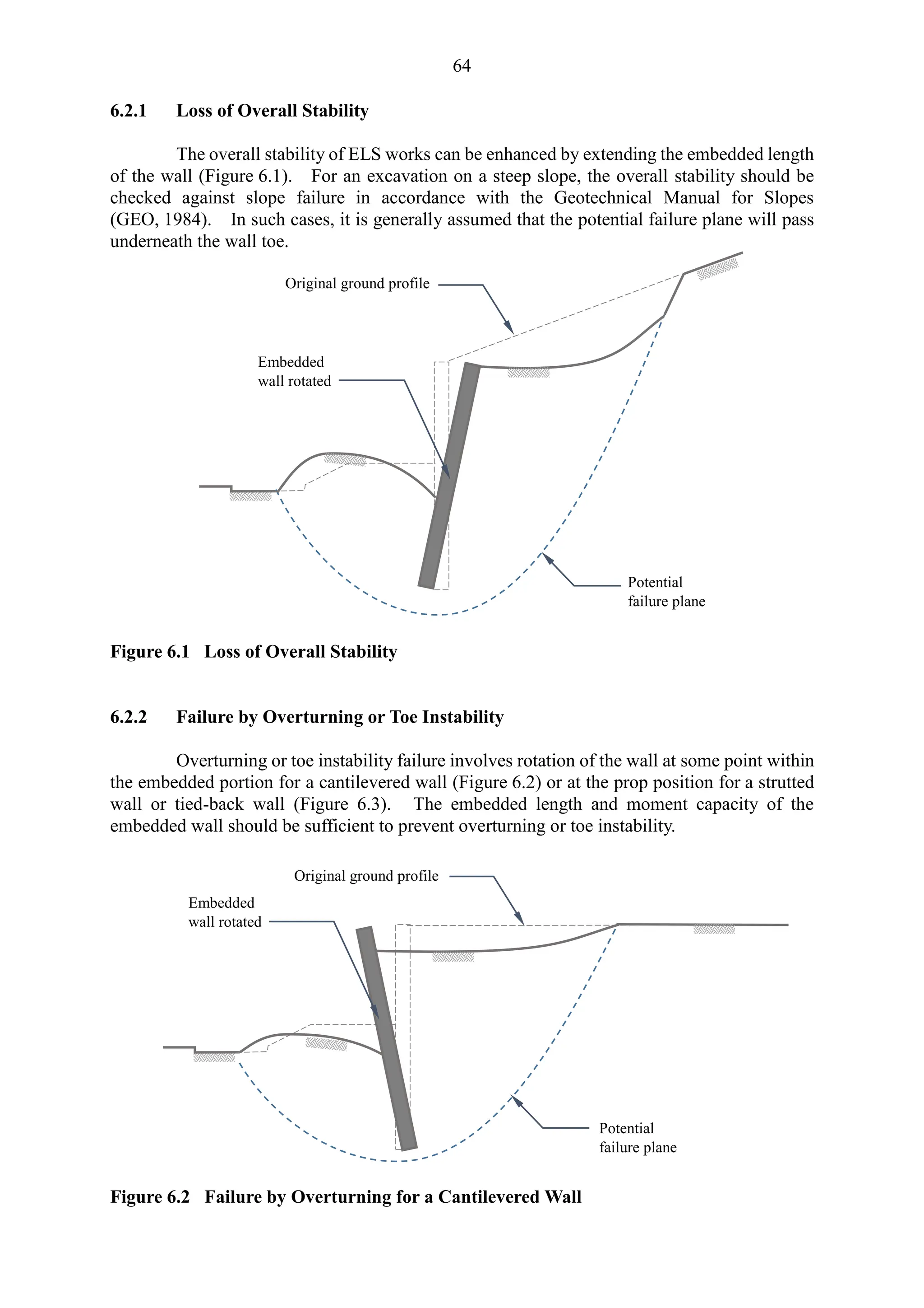
Geo Publication No. 1/2023 provides updated guidelines on deep excavation design and construction in Hong Kong, reflecting advancements in methods and technology since the previous standard published in 1990. This document aims to enhance economic design, reduce construction time, and improve ground deformation monitoring. It consolidates experiences from various stakeholders and encourages field monitoring to ensure the safety and effectiveness of excavation works.


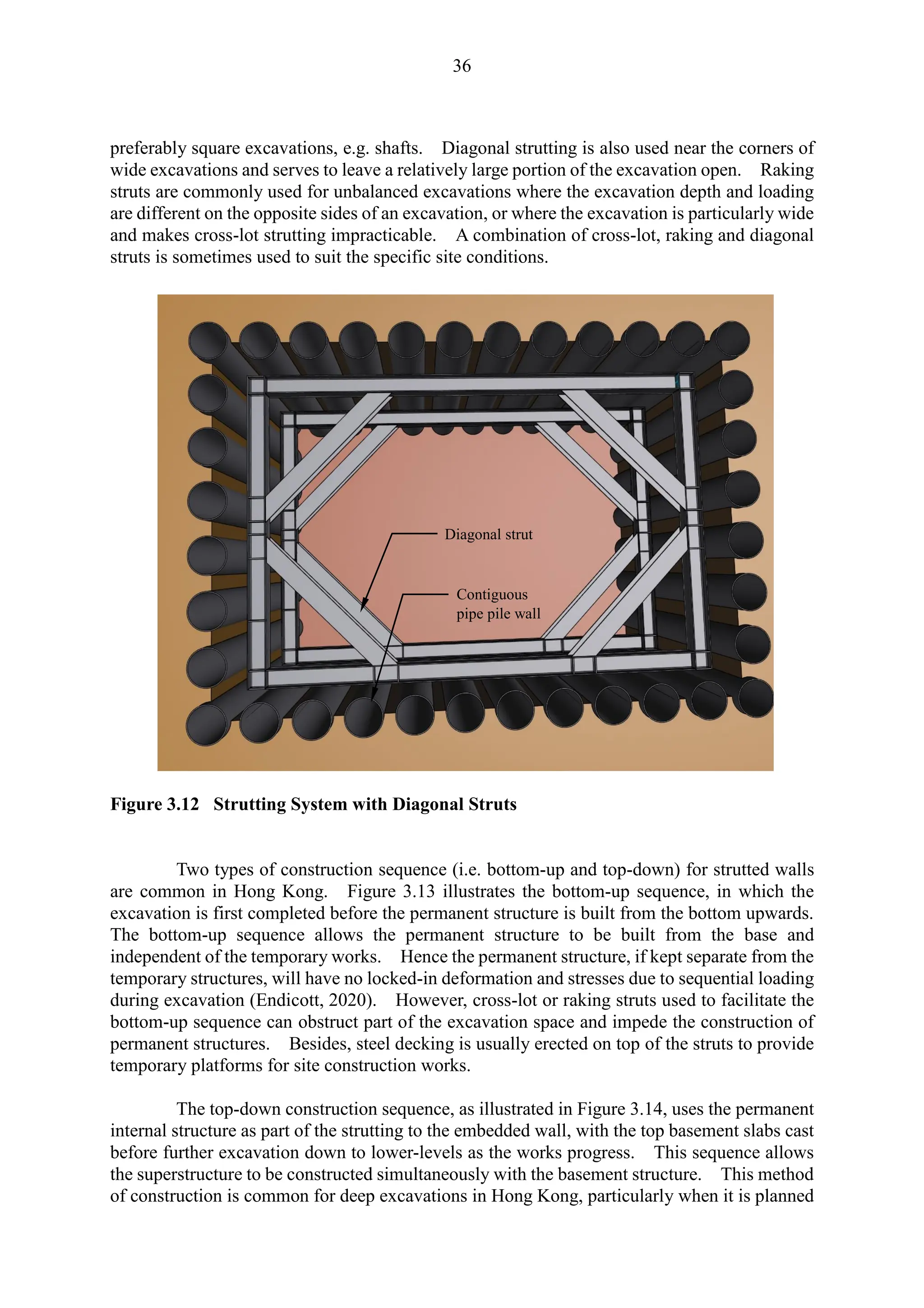


![87
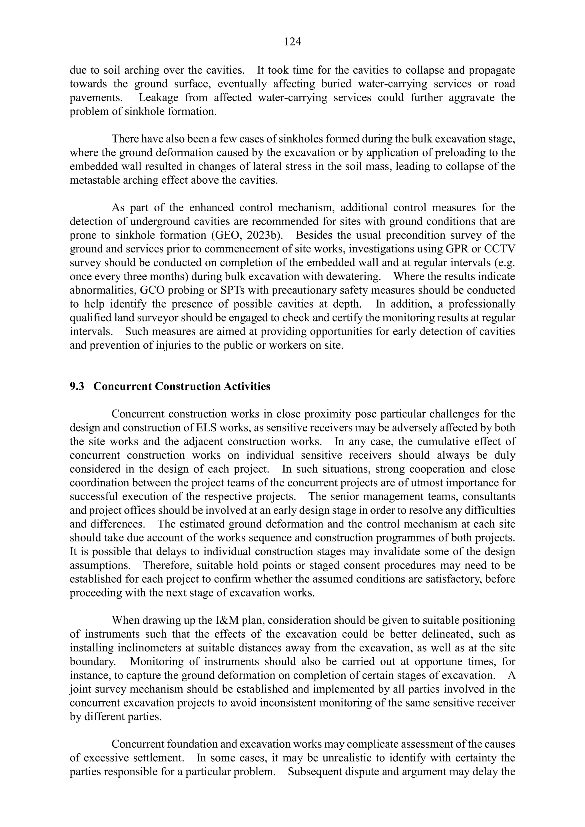
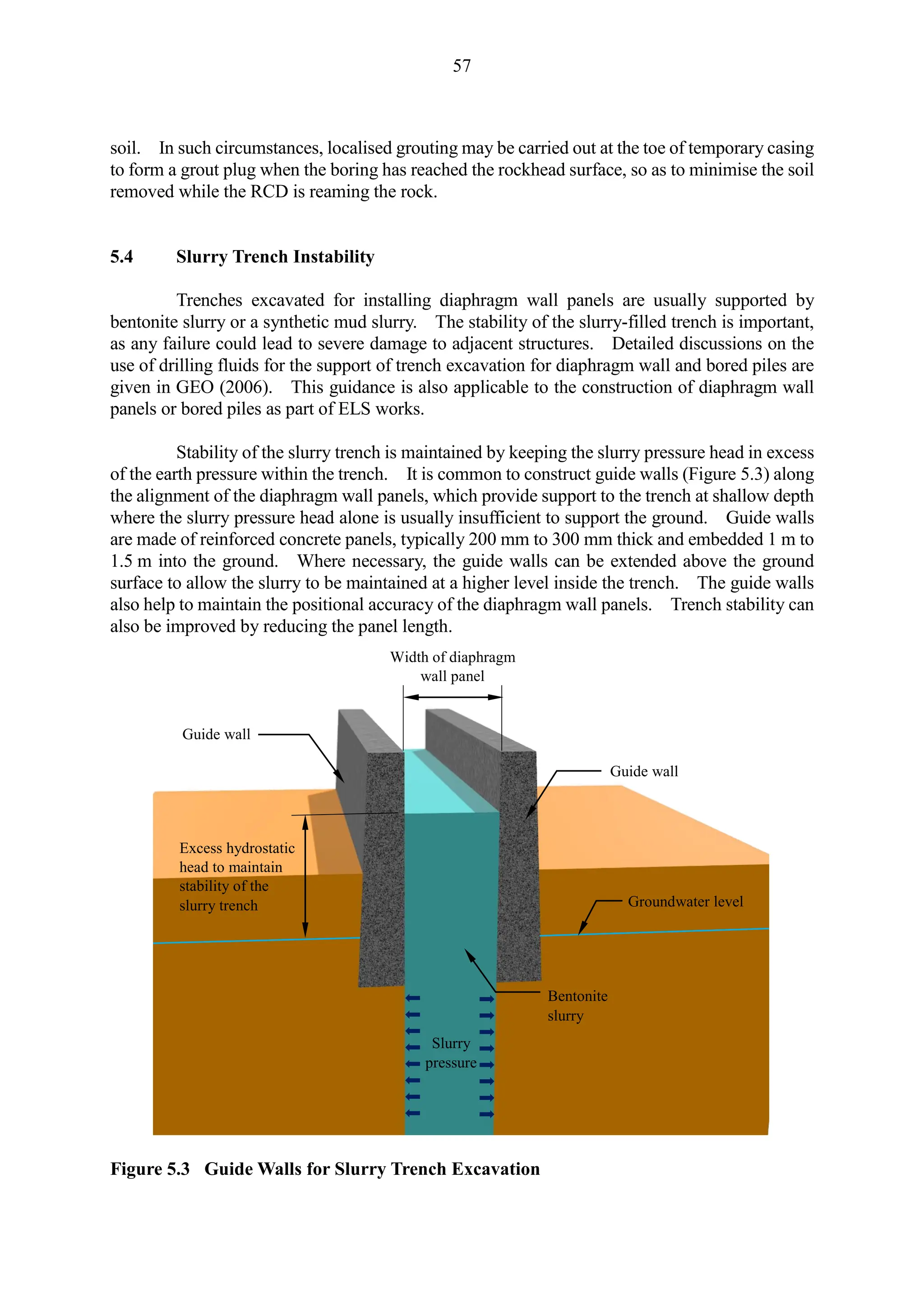
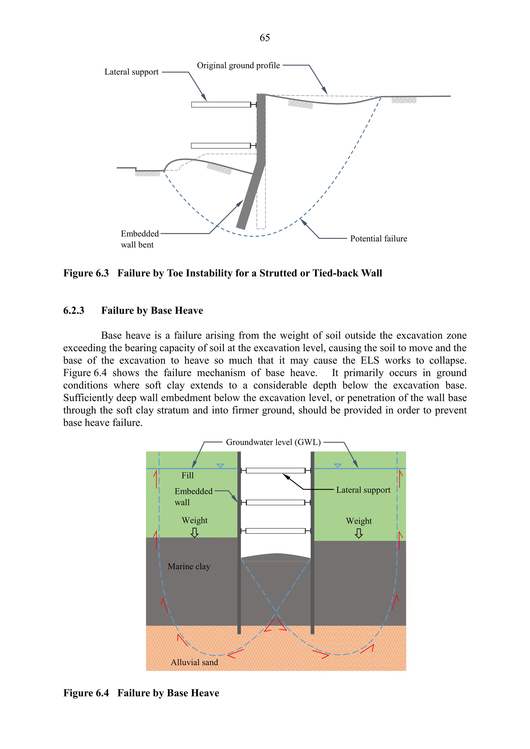
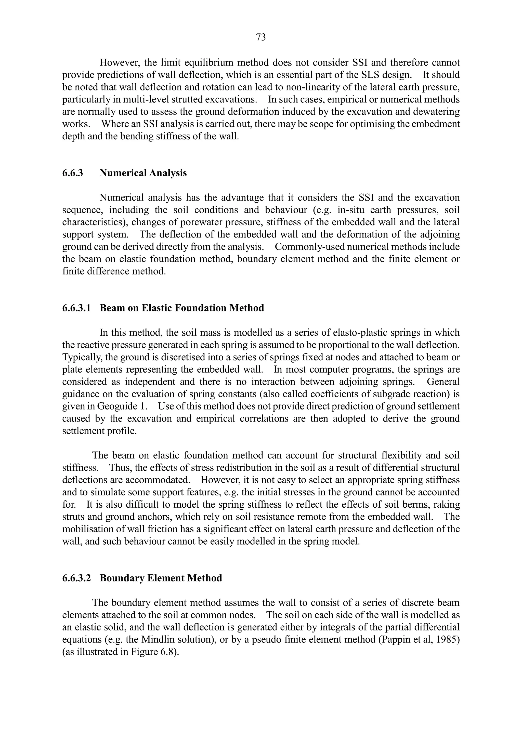
GFM:
hw + ( - w)z
u
≥ Required global factor of safety in Table 6.1
PFM: u mhww) z]
where uo = Groundwater pressure in the absence of flow
ud = Design groundwater pressure in the presence of flow
u = Pressure difference
= Bulk unit weight of soil
w = Unit weight of water
m = Partial material factor in Table 6.2
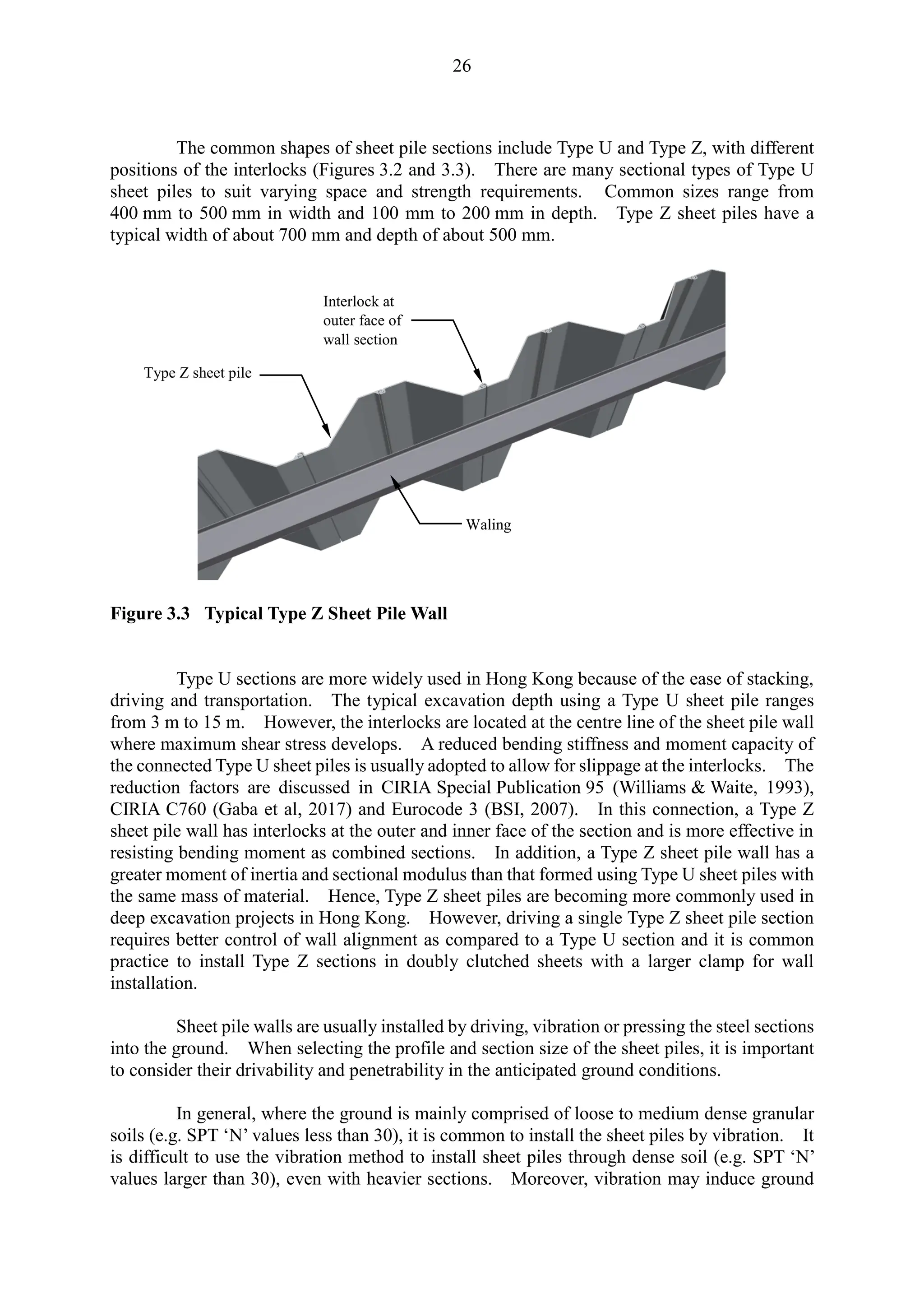
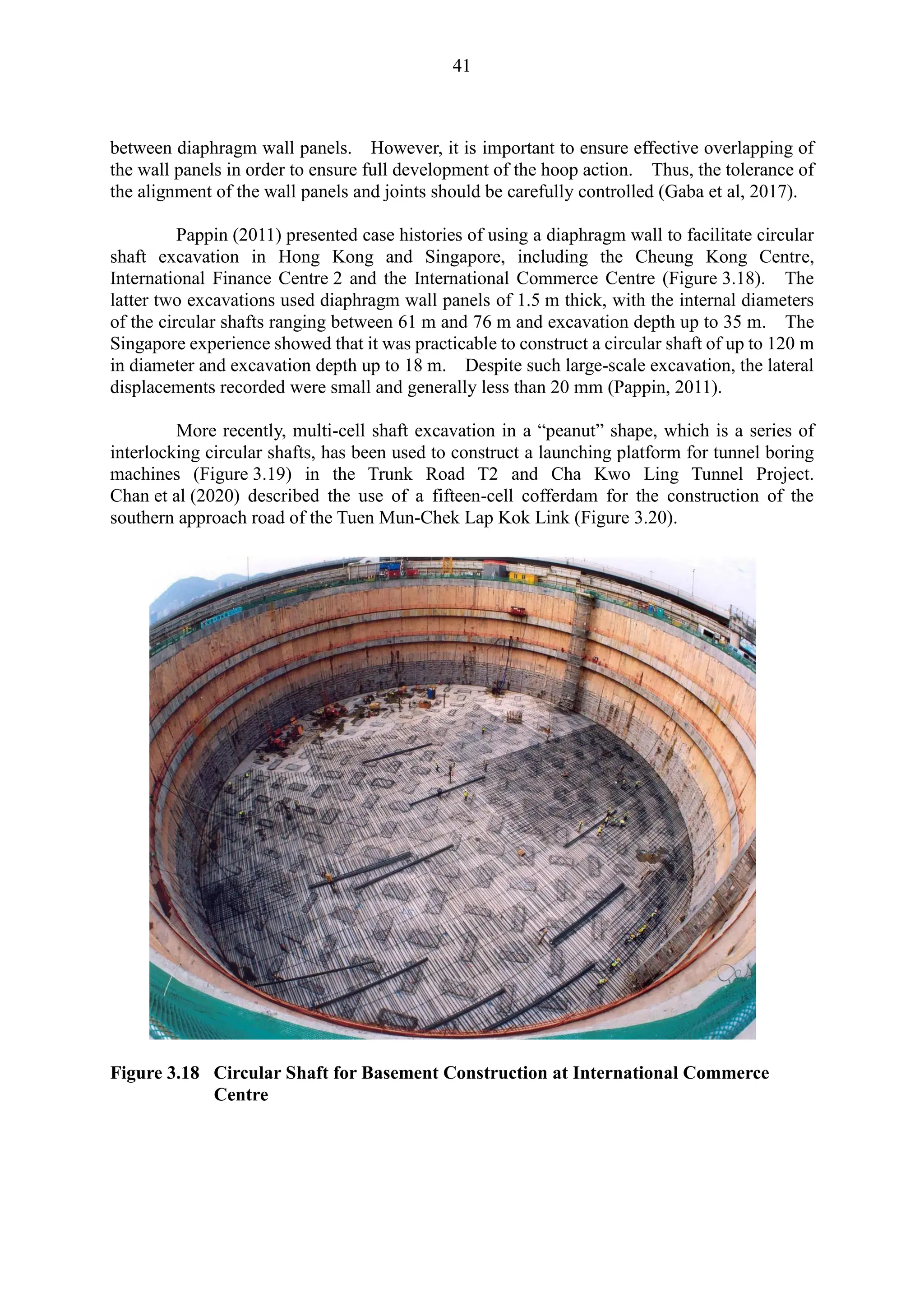
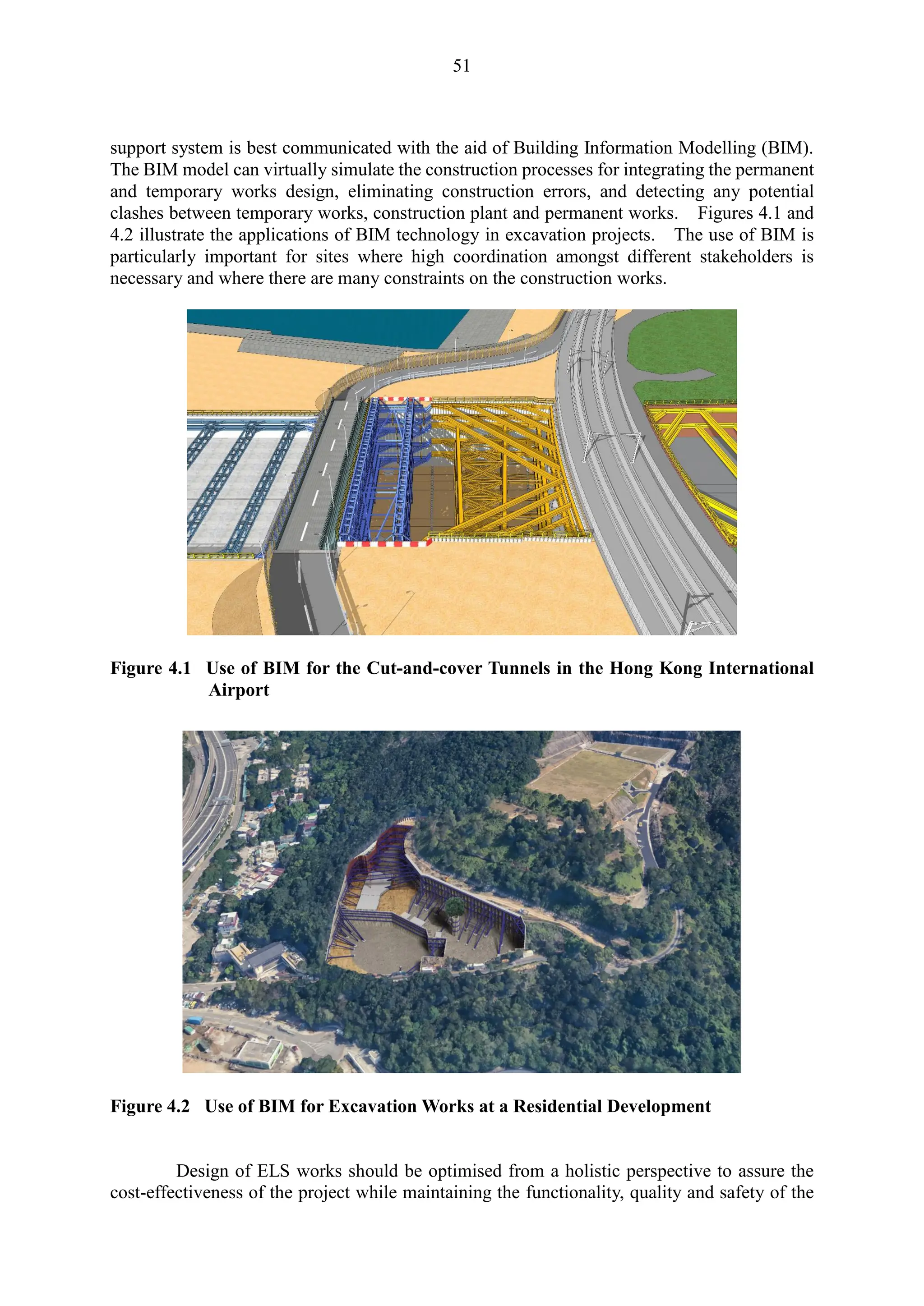
Figure 7.10 Method of Piping Analysis (modified from BSI, 2022)
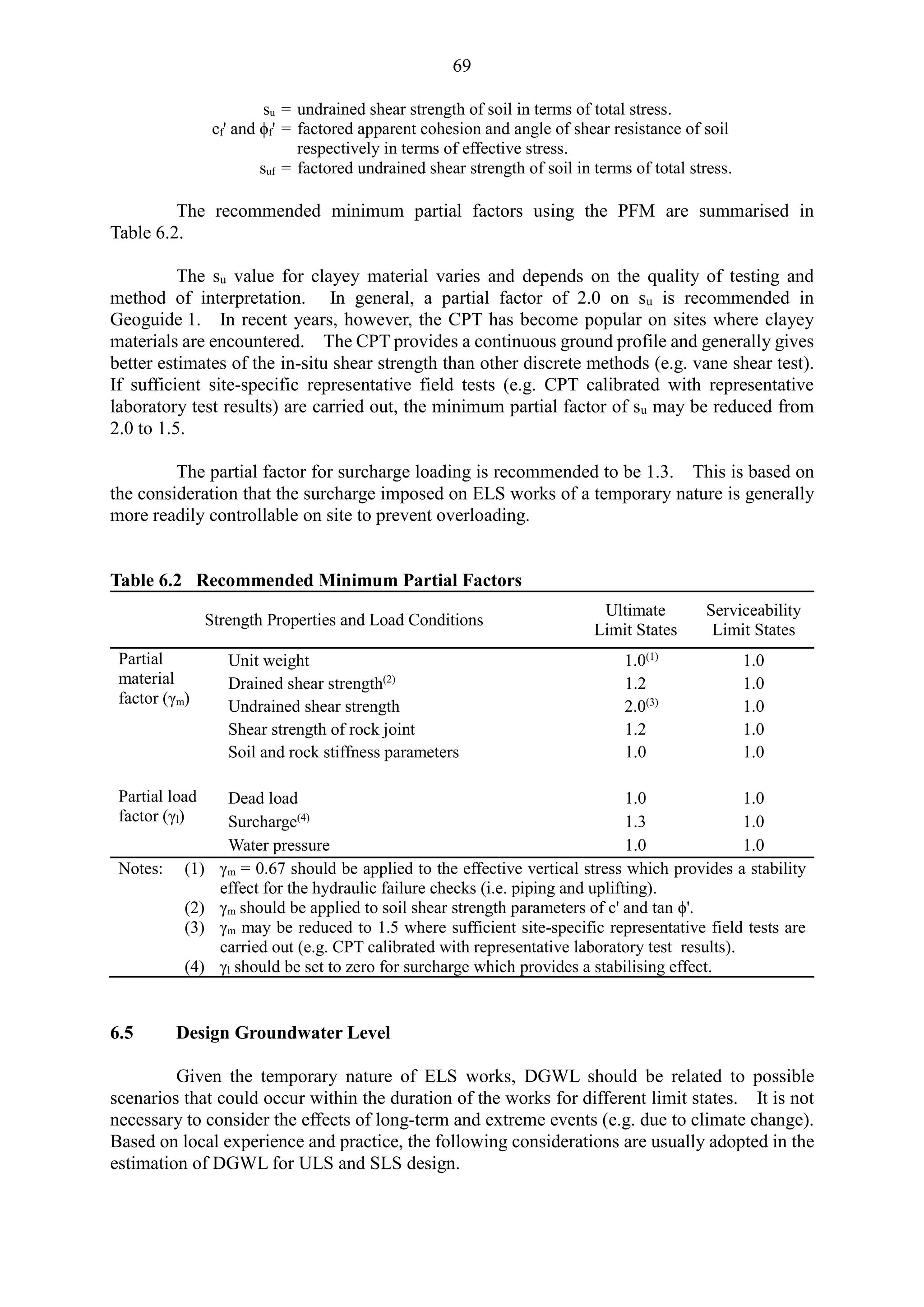
GFM:
h1 + h2
ua
≥ Required global factor of safety in Table 6.1
PFM: ua m (1h1 + 2h2)
where 1h1 + 2h2 = Total stress at the depth of (h1 + h2) on excavated side
ua = Groundwater pressure determined from seepage analysis
Figure 7.11 Method of Uplifting Analysis (modified from Ou, 2006)
h1
Impermeable layer
GWL
h2
Permeable layer
Permeable layer
ua
GWL
u
hw
ud
uo
z
ud
Dewatering level
GWL
GWL](https://image.slidesharecdn.com/deepexcavationdesignandconstruction2023-240730130925-ea0fe50c/75/Deep-Excavation-Design-and-Construction-_2023-pdf-87-2048.jpg)


![101
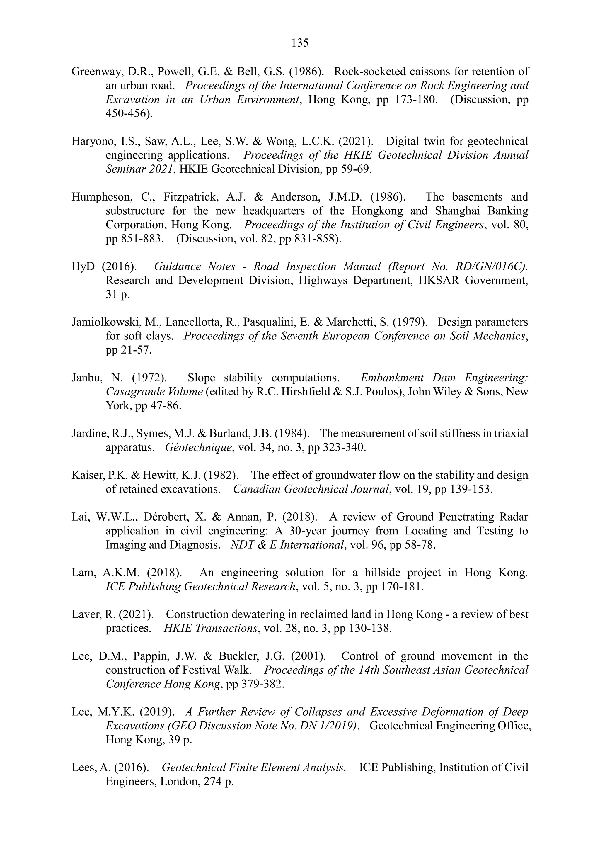
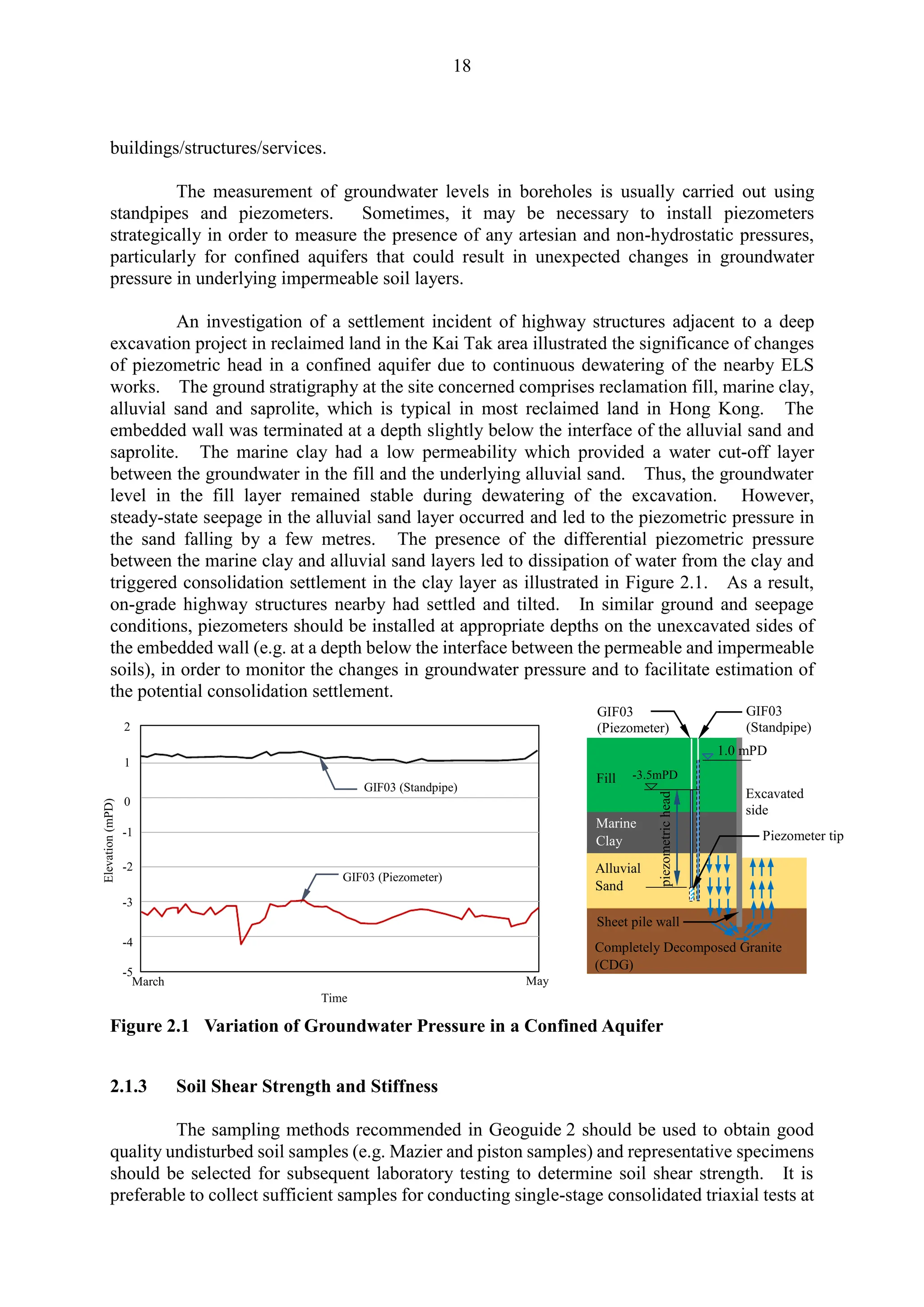
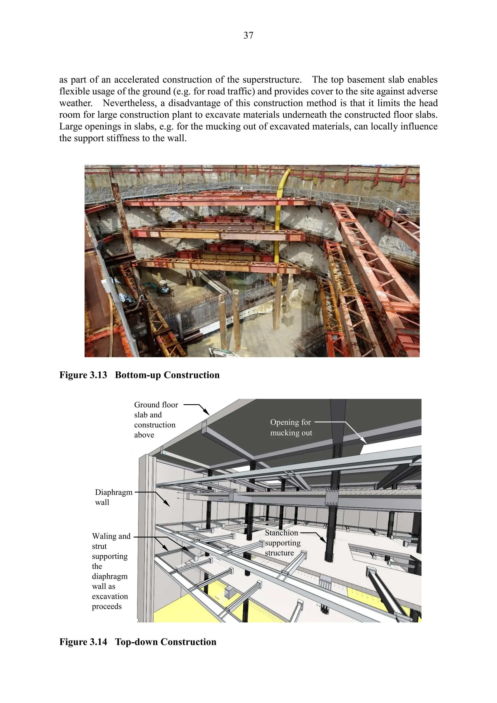
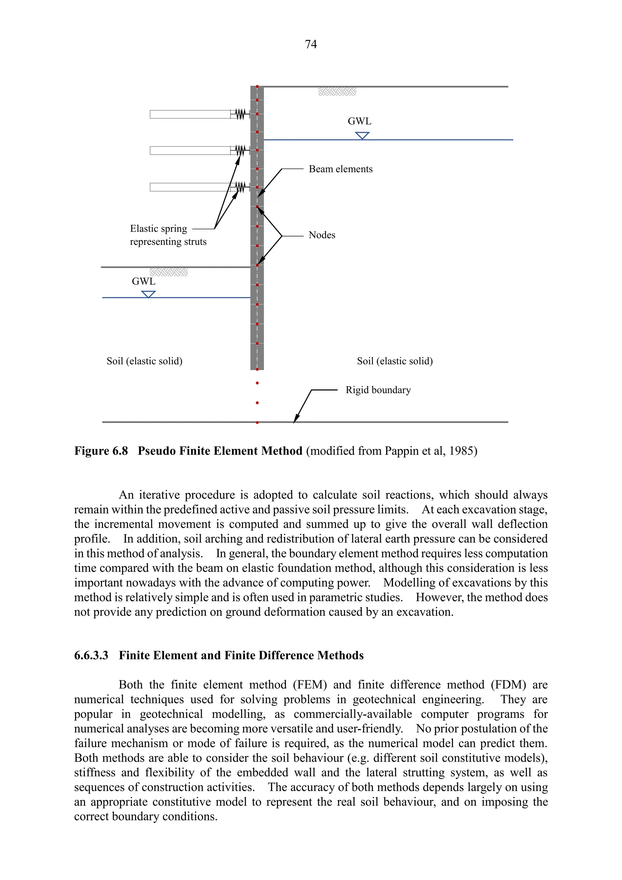
ground deformation was caused by a rise in the groundwater table as a result of the construction
of preceding wall panels, which reduced the effective slurry pressure supporting the subsequent
trench excavations. Pickles et al (2003) reported that the large ground settlement observed
during the diaphragm wall construction for the Tsuen Wan West Station was mainly associated
with the cobbles and boulders encountered in the buried old seawall structures. In a case
where ground improvement works were carried out prior to trenching at the roadworks at Kwun
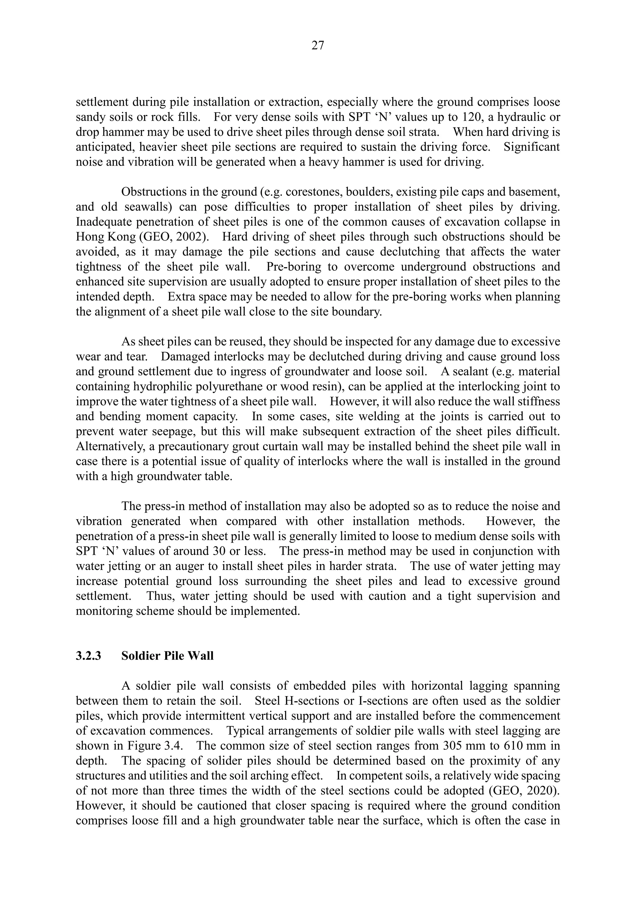
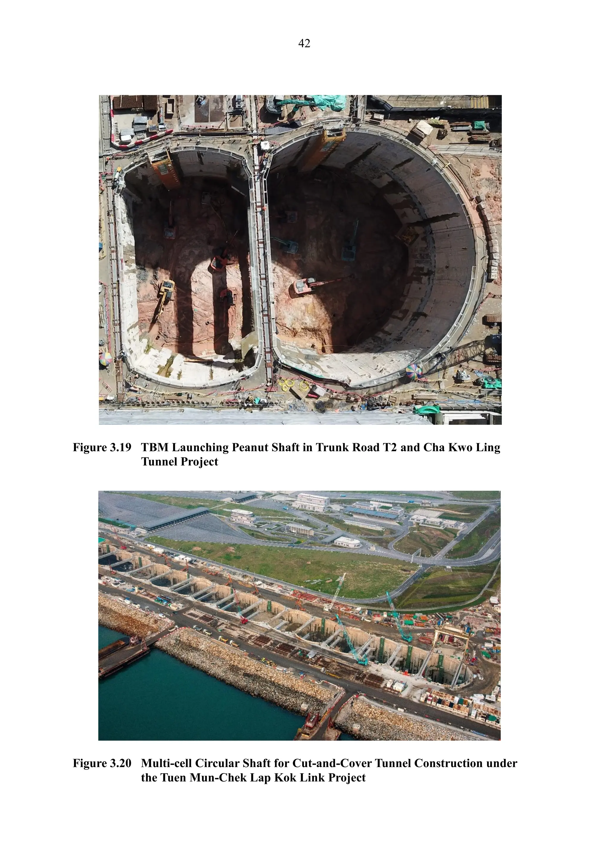
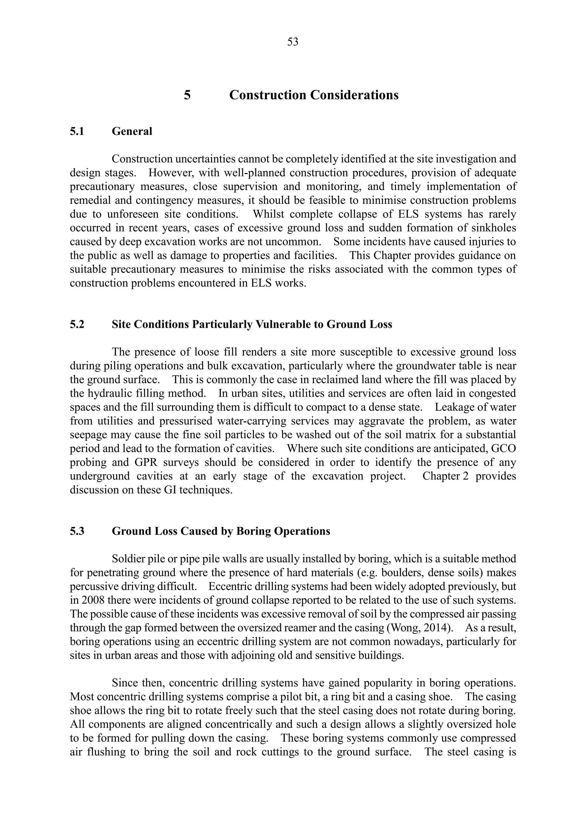
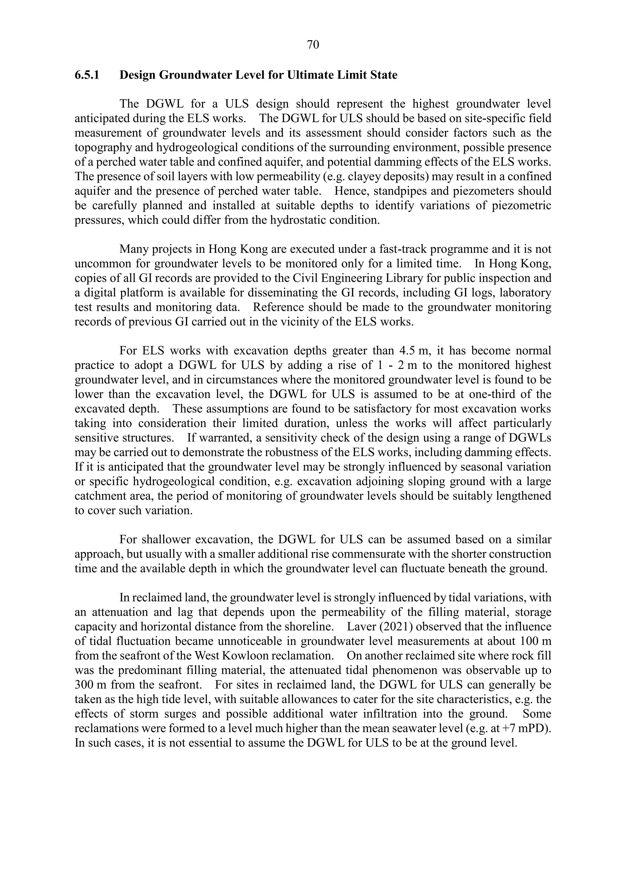
Tong, the induced ground settlement was only 0.02%Ht, which was about 10 mm (Figure 8.2).
Figure 8.2 Measured Ground Settlement due to Diaphragm Wall Installation from Case
Study Data
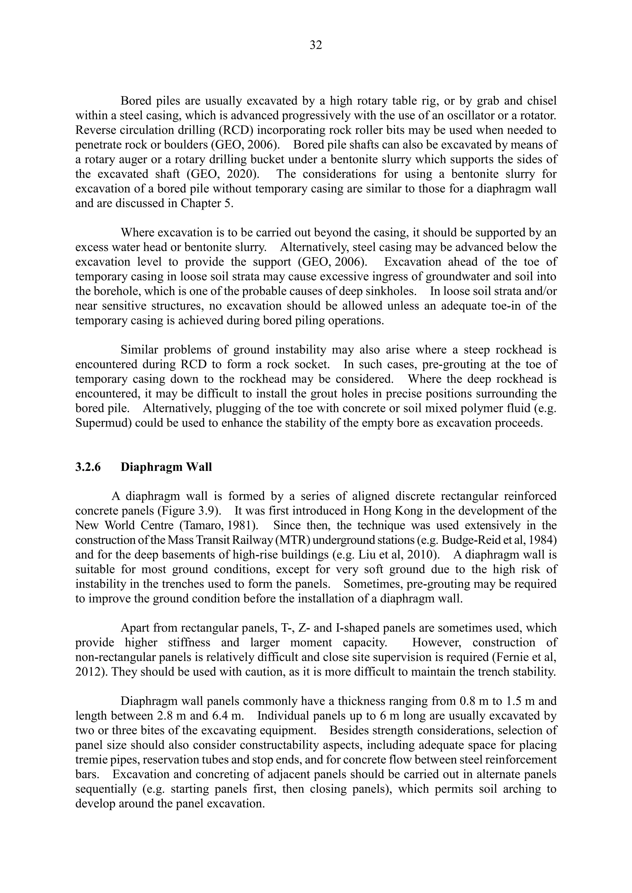
It is recommended that for estimating the effects of diaphragm wall panel construction,
a minimum ground settlement of about 0.05%Ht should be allowed for when assessing the
impact on nearby sensitive receivers. However, where the trench excavation involves removal
of corestones in saprolite or buried man-made ground features, a higher prescribed value may
be more appropriate. In competent ground conditions (e.g. dense saprolite), or if ground
improvement works have been implemented prior to trenching, the induced ground settlement
due to diaphragm wall installation might be less than the nominal value of 0.05%Ht. On the
other hand, ground settlement can be also assessed using either an empirical approach (e.g. by
referring to previous projects with similar ground conditions and wall panel geometry) or by a
numerical method. Site-specific trials should be undertaken to confirm the design slurry
pressure and the induced ground deformation.
Advanced numerical models have been used by some researchers to estimate the
ground deformation caused by the installation of driven or bored piles. However, applications
of such models in practice are still limited because of the simplifications and assumptions that
0
0.05
0.1
0.15
0.2
0.25
0.3
20 25 30 35 40 45 50
Settlement
due
to
wall
installation,
δ
v
/H
t
(%)
Diaphragm wall depth, Ht (m)
Chater Station, HK [37m]
HSBC HQ [30m]
Tsuen Wan West Station (old reclamation) [22m]
Sheung Wan Crossover [43m]
Tsuen Wan West Station (new reclamation) [35m]
Development at Admiralty [39m]
Development at To Kwa Wan [42m]
Roadworks at Kwun Tong [49m]
10 mm
20 mm
30 mm
Note: Value in bracket represents Ht](https://image.slidesharecdn.com/deepexcavationdesignandconstruction2023-240730130925-ea0fe50c/75/Deep-Excavation-Design-and-Construction-_2023-pdf-101-2048.jpg)