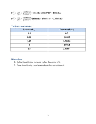
SlideShare a Scribd company logo
Koya university
faculty of engineering
Chemical engineering department
Dead-weight piston gouge
2022-2023
Prepared by : supervised by:
Dima Jawhar Mustafa Ms. Lameha A. ali
Srwa Tahir Mr. daban luqman
Rayan hawez
Sntia louay Sba
Danya amir
Experiment date :(30-Nov.-2022) Submitting date: (7-Dec.-2022)
2
Table of Contents
Aim of this experiment : ...............................................................................................................................3
introduction...................................................................................................................................................3
Table of Reading :.........................................................................................................................................8
Calculations : ............................................................................................................................................8
Table of calculations :...................................................................................................................................9
Discussions ...................................................................................................................................................9
References :................................................................................................................................................10
3
Aim of this experiment :
Calibrating the bourdon gauge. which is used to measure gauge Pressure.
introduction
The deadweight piston gauge (Bell and Howell) is used is to measure pressure in terms of
fundamental units - force and area. A piston is inserted into a close fitting cylinder. Weights are
placed on one end of the piston and are supported by fluid pressure applied to the other end. For
absolute pressure measurements the assembly is placed inside an evacuated bell jar. Pressure
measurements take into account a number of parameters affecting the instrument and its
environment.
The pressure is applied via weights which are placed on a weight support. The latter has a piston
which acts on hydraulic oil in a pipe system, so that a manometer which is also connected to the
system should indicate certain pressures. The device contains a Bourdon spring manometer with
a transparent dial. The display mechanism and the various adjustment opportunities are therefore
clearly identifiable. Hydraulic oil is used to transfer pressure.
Figure-1: Layout HM 150.02
Instructions :
1. Bourdon tube pressure gauge for pressure measurement
2. transparent dial face with a view of the spring mechanism
3. accurately fitting piston and cylinder of the piston manometer without seals
4. hydraulic oil for transfer of the force hydraulic pump with storage tank and bleed
mechanism The device for calibrating pressure gauges
4
essentially consists of two units:
1. The pressure gauge unit This is where the manometer to be calibrated is screwed in
2. The load unit The load unit consists of several weights and a cylinder with a piston. An
increase in the load results in an increase in pressure. The load unit is connected to the pressure
gauge unit via an oil-filled line, enabling the manometer to display the increase in pressure.
The following sectional drawing shows how the load unit and pressure gauge unit are connected:
Figure-4: Hydraulic connections.
both units are connected by means of a pipeline. When the support is loaded with weights, the oil
pressure in the system increases. The seal between the piston and the cylinder is metallic, with no
other sealing elements. The fit has been very carefully designed to ensure that the piston operates
almost entirely without friction, and with minimal oil leakage.
The weights are designed in such a way that pressure increments of 0,5bar are possible. Place
the small weight on the weight support first. A guide pin is provided for this purpose. The other
weights would lie askew on the plunger, and would corrupt the measurements due to different
levels of friction.
The unit is also equipped with a drain and filling plug in order to drain or fill the oil. The
compensation cylinder can be used to raise and lower the weight load on the oil cushion of the
hydraulic oil. For the measurements, the load must be kept on the oil cushion so that the pressure
is applied in the hydraulic system. After unscrewing the pressure relief knob, the weight load can
5
be brought down until it is supported. The hydraulic is then relieved of the load. In addition, the
compensation cylinder can be used to easily check the oil level and top it up if required.
NOTICE : Do not replace the pressure gauge. Oil can only be refilled using a vacuum.
Remove and Insert Transport Cap
The transport cap is held in the cylinder by an O-ring, not by a thread.
Figure-6: Remove transport cap:
• Push the compensation cylinder hand lever until the pressure increases. Hold the transport cap
securely and push the hand lever further until the transport cap is loose and can be removed.
NOTICE : Pressurized oil may squirt out of the opening.
Insert transport cap:
• Place transport cap in place. • Unscrew the pressure relief knob then press on the transport cap.
Screw the pressure relief knob back in.
Procedure:
• If necessary, top up oil and check zero balance. Push the hand lever down until the cylinder is
filled up to the brim. Insert the piston.
Zero Balance To check the zero point of the manometer, proceed as follows:
• Push the hand lever down so that the piston is pushed out of the cylinder. Remove the piston
and weight support. Adjust the oil level in the open cylinder until the cylinder is filled up to the
edge.
6
Figure-7: Insert transport cap.
• The manometer being tested should now indicate zero, as it is only subject to ambient pressure.
If this is not the case, the pointer on the pressure gauge can be adjusted with a small screwdriver.
For this, remove the front glass by turning the front ring.
NOTICE : The transparent dial of the spring-tube pressure gauge are made of glass and can
break.
Figure-8: Oil level (A).
Topping up the Hydraulic Oil If despite repeatedly operating the hand lever the oil does not
reach the brim of the cylinder, the oil must be topped up.
For this purpose, proceed as follows:
1. remove the piston with a weight support.
2. Pull hand lever to its highest position
3. Unscrew pressure relief knob
4. Top up oil to the first ledge
5. Fit piston with weight support
7
6. Push down piston with weight support
7. Screw in pressure relief knob
8. Perform zero balance in accordance with
Changing the Oil
Remove the drain and filling plug .Drain the old oil, bleed if necessary. Make an additional
screwed connection between the three-way valve and vacuum pump. NOTICE : A vacuum
pump and a three-way valve are not included in the content of supply. Open the three-way valve
so that the vacuum pump generates a vacuum. Reverse the three-way valve to allow oil into the
system. Then shut off the hydraulic system. NOTICE: Do not replace the pressure gauge. Oil
can only be refilled using a vacuum.
Figure-9: changing oil level.
Theory:
p : Pressure m : Mass of load unit g : Gravity constant
8
Preparation of Experiment
Remove the transport cap. Top up with oil if necessary and check the zero signal.
Performing the Experiment
Read off the zero signal on the pressure gauge, check it and make a note of it. Set the weight carrier to
0,334bar by inserting the piston in the load unit cylinder. To do this: 1. Unscrew pressure relief knob 2.
Press down weight support 3. Screw in pressure relief knob. Press down the hand lever, thereby slowly
lifting the piston with weight support until it just floats on the oil with sufficient guidance. To avoid
sticking due to static friction, gently twist the weight carrier as it sinks. Note the pressure signal on the
pressure gauge. Place the load ring for 0,166bar on the weight carrier. When so doing, make sure that the
weight carrier floats freely on the oil. To minimize sticking due to static friction whilst performing this
measurement, gently twist the weight carrier. Note the pressure signal on the pressure gauge. Add each of
the other four load rings for 0,5bar in turn, repeating the action described above and noting the pressure
values.
Table of Reading :
Mass (g) Pressure (bar)
578 0.5
578(2) 0.96
578(3) 1.47
578(4) 2
578(5) 2.5
Calculations :
Mass= 198 + 380 =578 g
P=
𝑭
𝑨
=
𝒎𝒈
𝝅
𝟒
𝑹^𝟐
=
𝟎.𝟓𝟕𝟖∗𝟗.𝟖𝟏
𝝅
𝟒
(𝟎.𝟎𝟏𝟐)^𝟐
=50000 Pa= 50000*10-5
= 0.5Bar
P=
𝑭
𝑨
=
𝒎𝒈
𝝅
𝟒
𝑹^𝟐
=
𝟐∗𝟎.𝟓𝟕𝟖∗𝟗.𝟖𝟏
𝝅
𝟒
(𝟎.𝟎𝟏𝟐)^𝟐
=100000Pa= 100000*10-5
= 1.0032Bar
P=
𝑭
𝑨
=
𝒎𝒈
𝝅
𝟒
𝑹^𝟐
=
𝟑∗𝟎.𝟓𝟕𝟖∗𝟗.𝟖𝟏
𝝅
𝟒
(𝟎.𝟎𝟏𝟐)^𝟐
=150482Pa= 150482*10-5
= 1.50482Bar
9
P=
𝑭
𝑨
=
𝒎𝒈
𝝅
𝟒
𝑹^𝟐
=
𝟒∗𝟎.𝟓𝟕𝟖∗𝟗.𝟖𝟏
𝝅
𝟒
(𝟎.𝟎𝟏𝟐)^𝟐
= 200643Pa=200643*10-5
= 2.0064Bar
P=
𝑭
𝑨
=
𝒎𝒈
𝝅
𝟒
𝑹^𝟐
=
𝟓∗𝟎.𝟓𝟕𝟖∗𝟗.𝟖𝟏
𝝅
𝟒
(𝟎.𝟎𝟏𝟐)^𝟐
=250804 Pa= 250804*10-5
= 2.50804Bar
Table of calculations :
Pressure(Pm) Pressure (Pact)
0.5 0.5
0.96 1.0032
1.47 1.50482
2 2.0064
2.5 2.50804
Discussions
1. Define the calibrating curve and explain the purpose of it.
2. Draw the calibrating curve between Pm & Pact. then discuss it.
10
References :
1. G.U.N.T. Gerätebau ,(2021) GmbH, Hanskampring 15-17, D-22885 Barsbüttel.[e.book].
available : https://www.gunt.de/images/datasheet/549/HM-150.02-Calibration-of-
pressure-gauges-gunt-549-pdf_1_en-GB.pdf [accessed : 30/dec./2022]
2. imamu(2016), Dead-weight piston gouge experiment instructions.[online]. Available :
https://units.imamu.edu.sa/colleges/en/Engineering/studyprograms/Documents/ME%20L
ab%20Manuals/Lab%20Equipment%20info/Thermo-fluids%20Lab/HM150_02e%20-
%20V0.2_Dead_weight_piston_gauge.pdf [accessed : 30/dec./2022]
3. archive.eol,(2018), Dead Weight Piston Gauge.[online]. Available :
https://archive.eol.ucar.edu/docs/isf/facilities/callab/deadweight.html?fbclid=IwAR2LDD
cObCTs3tjEymzDs27j6lKUNwBGs6nsdyjmjdHMMd3kmxjsF5awRmQ#:~:text=The%2
0deadweight%20piston%20gauge%20 [accessed : 30/dec./2022]
4. aree S.( May. 09, 2014), Dead Weight Piston Gauge.[online]. Available :
https://www.slideshare.net/areesalah/deadweight-piston-
gauge?fbclid=IwAR0oTlEdqS_ajhLBOSbAuxKcXPBz3XeFZ0Sl1v1YptN4IujmaYl95y
TDjag [accessed : 30/dec./2022]

More Related Content

Similar to deadweight piston gauge

Jcb 1 t 1 high tip dumper service repair manual (sn 2561001 and up)
Jcb 1 t 1 high tip dumper service repair manual (sn 2561001 and up)Jcb 1 t 1 high tip dumper service repair manual (sn 2561001 and up)
Jcb 1 t 1 high tip dumper service repair manual (sn 2561001 and up)
udjfjjskekkem
 
Jcb 1 t 1 high tip dumper service repair manual (sn 2561001 and up)
Jcb 1 t 1 high tip dumper service repair manual (sn 2561001 and up)Jcb 1 t 1 high tip dumper service repair manual (sn 2561001 and up)
Jcb 1 t 1 high tip dumper service repair manual (sn 2561001 and up)
udfjjssekkemm
 
Jcb 1 t 1 high tip dumper service repair manual (sn 2561001 and up)
Jcb 1 t 1 high tip dumper service repair manual (sn 2561001 and up)Jcb 1 t 1 high tip dumper service repair manual (sn 2561001 and up)
Jcb 1 t 1 high tip dumper service repair manual (sn 2561001 and up)
fusjefjskekemm
 
Jcb 1 t 1 high tip dumper service repair manual (sn 2561001 and up)
Jcb 1 t 1 high tip dumper service repair manual (sn 2561001 and up)Jcb 1 t 1 high tip dumper service repair manual (sn 2561001 and up)
Jcb 1 t 1 high tip dumper service repair manual (sn 2561001 and up)
fjseolseksmem
 
bnt68 introduction
bnt68 introductionbnt68 introduction
bnt68 introductionMona Lisa
 
Volvo ec390 excavator service repair manual
Volvo ec390 excavator service repair manualVolvo ec390 excavator service repair manual
Volvo ec390 excavator service repair manual
jfkseksmemqw
 
Checking piston valve clearance
Checking piston valve clearanceChecking piston valve clearance
Checking piston valve clearance
Jomer Almozara
 
Fluid flow lab3-Dead –Weight piston gauge dec 2015
Fluid flow lab3-Dead –Weight piston gauge  dec 2015Fluid flow lab3-Dead –Weight piston gauge  dec 2015
Fluid flow lab3-Dead –Weight piston gauge dec 2015
Zhyar Arsalan
 

Similar to deadweight piston gauge (9)

Jcb 1 t 1 high tip dumper service repair manual (sn 2561001 and up)
Jcb 1 t 1 high tip dumper service repair manual (sn 2561001 and up)Jcb 1 t 1 high tip dumper service repair manual (sn 2561001 and up)
Jcb 1 t 1 high tip dumper service repair manual (sn 2561001 and up)
 
Jcb 1 t 1 high tip dumper service repair manual (sn 2561001 and up)
Jcb 1 t 1 high tip dumper service repair manual (sn 2561001 and up)Jcb 1 t 1 high tip dumper service repair manual (sn 2561001 and up)
Jcb 1 t 1 high tip dumper service repair manual (sn 2561001 and up)
 
Jcb 1 t 1 high tip dumper service repair manual (sn 2561001 and up)
Jcb 1 t 1 high tip dumper service repair manual (sn 2561001 and up)Jcb 1 t 1 high tip dumper service repair manual (sn 2561001 and up)
Jcb 1 t 1 high tip dumper service repair manual (sn 2561001 and up)
 
Jcb 1 t 1 high tip dumper service repair manual (sn 2561001 and up)
Jcb 1 t 1 high tip dumper service repair manual (sn 2561001 and up)Jcb 1 t 1 high tip dumper service repair manual (sn 2561001 and up)
Jcb 1 t 1 high tip dumper service repair manual (sn 2561001 and up)
 
bnt68 introduction
bnt68 introductionbnt68 introduction
bnt68 introduction
 
Ohv.reassembly
Ohv.reassemblyOhv.reassembly
Ohv.reassembly
 
Volvo ec390 excavator service repair manual
Volvo ec390 excavator service repair manualVolvo ec390 excavator service repair manual
Volvo ec390 excavator service repair manual
 
Checking piston valve clearance
Checking piston valve clearanceChecking piston valve clearance
Checking piston valve clearance
 
Fluid flow lab3-Dead –Weight piston gauge dec 2015
Fluid flow lab3-Dead –Weight piston gauge  dec 2015Fluid flow lab3-Dead –Weight piston gauge  dec 2015
Fluid flow lab3-Dead –Weight piston gauge dec 2015
 

More from DimaJawhar

reactor lab single CSTR reactor.pdf
reactor lab single CSTR reactor.pdfreactor lab single CSTR reactor.pdf
reactor lab single CSTR reactor.pdf
DimaJawhar
 
double pip heat exchanger lab
double pip heat exchanger labdouble pip heat exchanger lab
double pip heat exchanger lab
DimaJawhar
 
reactor design batch reactor
reactor design batch reactorreactor design batch reactor
reactor design batch reactor
DimaJawhar
 
reactor design lab continuous stirred tank reactor
reactor design lab continuous stirred tank reactorreactor design lab continuous stirred tank reactor
reactor design lab continuous stirred tank reactor
DimaJawhar
 
000-Natural gas processing.pdf
000-Natural gas processing.pdf000-Natural gas processing.pdf
000-Natural gas processing.pdf
DimaJawhar
 
natural gas process
natural gas processnatural gas process
natural gas process
DimaJawhar
 
chemical industries: water treatment flocculation tank
chemical industries: water treatment flocculation tankchemical industries: water treatment flocculation tank
chemical industries: water treatment flocculation tank
DimaJawhar
 
countercurrent heat exchanger lab 2023.pdf
countercurrent  heat exchanger lab 2023.pdfcountercurrent  heat exchanger lab 2023.pdf
countercurrent heat exchanger lab 2023.pdf
DimaJawhar
 
heat transfer in buildings.pdf
heat transfer in buildings.pdfheat transfer in buildings.pdf
heat transfer in buildings.pdf
DimaJawhar
 
chemical industries cement industry rotary Kiln.2023.pdf
chemical industries cement industry rotary Kiln.2023.pdfchemical industries cement industry rotary Kiln.2023.pdf
chemical industries cement industry rotary Kiln.2023.pdf
DimaJawhar
 
Chemical Reaction Engineering Catalysts in Chemical Reactor Designs
Chemical Reaction EngineeringCatalysts in Chemical Reactor Designs Chemical Reaction EngineeringCatalysts in Chemical Reactor Designs
Chemical Reaction Engineering Catalysts in Chemical Reactor Designs
DimaJawhar
 
Double Pipe Heat Exchanger Experiment
Double Pipe Heat Exchanger ExperimentDouble Pipe Heat Exchanger Experiment
Double Pipe Heat Exchanger Experiment
DimaJawhar
 
Bernoulli equation
Bernoulli equationBernoulli equation
Bernoulli equation
DimaJawhar
 
sulfur content
sulfur contentsulfur content
sulfur content
DimaJawhar
 
temperature measurement
temperature measurementtemperature measurement
temperature measurement
DimaJawhar
 
lifting force
lifting forcelifting force
lifting force
DimaJawhar
 
Dew point
Dew pointDew point
Dew point
DimaJawhar
 
flash point
flash pointflash point
flash point
DimaJawhar
 
boyle's law
boyle's lawboyle's law
boyle's law
DimaJawhar
 
equation of state
equation of stateequation of state
equation of state
DimaJawhar
 

More from DimaJawhar (20)

reactor lab single CSTR reactor.pdf
reactor lab single CSTR reactor.pdfreactor lab single CSTR reactor.pdf
reactor lab single CSTR reactor.pdf
 
double pip heat exchanger lab
double pip heat exchanger labdouble pip heat exchanger lab
double pip heat exchanger lab
 
reactor design batch reactor
reactor design batch reactorreactor design batch reactor
reactor design batch reactor
 
reactor design lab continuous stirred tank reactor
reactor design lab continuous stirred tank reactorreactor design lab continuous stirred tank reactor
reactor design lab continuous stirred tank reactor
 
000-Natural gas processing.pdf
000-Natural gas processing.pdf000-Natural gas processing.pdf
000-Natural gas processing.pdf
 
natural gas process
natural gas processnatural gas process
natural gas process
 
chemical industries: water treatment flocculation tank
chemical industries: water treatment flocculation tankchemical industries: water treatment flocculation tank
chemical industries: water treatment flocculation tank
 
countercurrent heat exchanger lab 2023.pdf
countercurrent  heat exchanger lab 2023.pdfcountercurrent  heat exchanger lab 2023.pdf
countercurrent heat exchanger lab 2023.pdf
 
heat transfer in buildings.pdf
heat transfer in buildings.pdfheat transfer in buildings.pdf
heat transfer in buildings.pdf
 
chemical industries cement industry rotary Kiln.2023.pdf
chemical industries cement industry rotary Kiln.2023.pdfchemical industries cement industry rotary Kiln.2023.pdf
chemical industries cement industry rotary Kiln.2023.pdf
 
Chemical Reaction Engineering Catalysts in Chemical Reactor Designs
Chemical Reaction EngineeringCatalysts in Chemical Reactor Designs Chemical Reaction EngineeringCatalysts in Chemical Reactor Designs
Chemical Reaction Engineering Catalysts in Chemical Reactor Designs
 
Double Pipe Heat Exchanger Experiment
Double Pipe Heat Exchanger ExperimentDouble Pipe Heat Exchanger Experiment
Double Pipe Heat Exchanger Experiment
 
Bernoulli equation
Bernoulli equationBernoulli equation
Bernoulli equation
 
sulfur content
sulfur contentsulfur content
sulfur content
 
temperature measurement
temperature measurementtemperature measurement
temperature measurement
 
lifting force
lifting forcelifting force
lifting force
 
Dew point
Dew pointDew point
Dew point
 
flash point
flash pointflash point
flash point
 
boyle's law
boyle's lawboyle's law
boyle's law
 
equation of state
equation of stateequation of state
equation of state
 

Recently uploaded

Top 10 Oil and Gas Projects in Saudi Arabia 2024.pdf
Top 10 Oil and Gas Projects in Saudi Arabia 2024.pdfTop 10 Oil and Gas Projects in Saudi Arabia 2024.pdf
Top 10 Oil and Gas Projects in Saudi Arabia 2024.pdf
Teleport Manpower Consultant
 
WATER CRISIS and its solutions-pptx 1234
WATER CRISIS and its solutions-pptx 1234WATER CRISIS and its solutions-pptx 1234
WATER CRISIS and its solutions-pptx 1234
AafreenAbuthahir2
 
Vaccine management system project report documentation..pdf
Vaccine management system project report documentation..pdfVaccine management system project report documentation..pdf
Vaccine management system project report documentation..pdf
Kamal Acharya
 
AKS UNIVERSITY Satna Final Year Project By OM Hardaha.pdf
AKS UNIVERSITY Satna Final Year Project By OM Hardaha.pdfAKS UNIVERSITY Satna Final Year Project By OM Hardaha.pdf
AKS UNIVERSITY Satna Final Year Project By OM Hardaha.pdf
SamSarthak3
 
ethical hacking in wireless-hacking1.ppt
ethical hacking in wireless-hacking1.pptethical hacking in wireless-hacking1.ppt
ethical hacking in wireless-hacking1.ppt
Jayaprasanna4
 
DESIGN A COTTON SEED SEPARATION MACHINE.docx
DESIGN A COTTON SEED SEPARATION MACHINE.docxDESIGN A COTTON SEED SEPARATION MACHINE.docx
DESIGN A COTTON SEED SEPARATION MACHINE.docx
FluxPrime1
 
NO1 Uk best vashikaran specialist in delhi vashikaran baba near me online vas...
NO1 Uk best vashikaran specialist in delhi vashikaran baba near me online vas...NO1 Uk best vashikaran specialist in delhi vashikaran baba near me online vas...
NO1 Uk best vashikaran specialist in delhi vashikaran baba near me online vas...
Amil Baba Dawood bangali
 
Forklift Classes Overview by Intella Parts
Forklift Classes Overview by Intella PartsForklift Classes Overview by Intella Parts
Forklift Classes Overview by Intella Parts
Intella Parts
 
COLLEGE BUS MANAGEMENT SYSTEM PROJECT REPORT.pdf
COLLEGE BUS MANAGEMENT SYSTEM PROJECT REPORT.pdfCOLLEGE BUS MANAGEMENT SYSTEM PROJECT REPORT.pdf
COLLEGE BUS MANAGEMENT SYSTEM PROJECT REPORT.pdf
Kamal Acharya
 
ASME IX(9) 2007 Full Version .pdf
ASME IX(9)  2007 Full Version       .pdfASME IX(9)  2007 Full Version       .pdf
ASME IX(9) 2007 Full Version .pdf
AhmedHussein950959
 
H.Seo, ICLR 2024, MLILAB, KAIST AI.pdf
H.Seo,  ICLR 2024, MLILAB,  KAIST AI.pdfH.Seo,  ICLR 2024, MLILAB,  KAIST AI.pdf
H.Seo, ICLR 2024, MLILAB, KAIST AI.pdf
MLILAB
 
Sachpazis:Terzaghi Bearing Capacity Estimation in simple terms with Calculati...
Sachpazis:Terzaghi Bearing Capacity Estimation in simple terms with Calculati...Sachpazis:Terzaghi Bearing Capacity Estimation in simple terms with Calculati...
Sachpazis:Terzaghi Bearing Capacity Estimation in simple terms with Calculati...
Dr.Costas Sachpazis
 
CFD Simulation of By-pass Flow in a HRSG module by R&R Consult.pptx
CFD Simulation of By-pass Flow in a HRSG module by R&R Consult.pptxCFD Simulation of By-pass Flow in a HRSG module by R&R Consult.pptx
CFD Simulation of By-pass Flow in a HRSG module by R&R Consult.pptx
R&R Consult
 
block diagram and signal flow graph representation
block diagram and signal flow graph representationblock diagram and signal flow graph representation
block diagram and signal flow graph representation
Divya Somashekar
 
Planning Of Procurement o different goods and services
Planning Of Procurement o different goods and servicesPlanning Of Procurement o different goods and services
Planning Of Procurement o different goods and services
JoytuBarua2
 
CME397 Surface Engineering- Professional Elective
CME397 Surface Engineering- Professional ElectiveCME397 Surface Engineering- Professional Elective
CME397 Surface Engineering- Professional Elective
karthi keyan
 
Quality defects in TMT Bars, Possible causes and Potential Solutions.
Quality defects in TMT Bars, Possible causes and Potential Solutions.Quality defects in TMT Bars, Possible causes and Potential Solutions.
Quality defects in TMT Bars, Possible causes and Potential Solutions.
PrashantGoswami42
 
Water Industry Process Automation and Control Monthly - May 2024.pdf
Water Industry Process Automation and Control Monthly - May 2024.pdfWater Industry Process Automation and Control Monthly - May 2024.pdf
Water Industry Process Automation and Control Monthly - May 2024.pdf
Water Industry Process Automation & Control
 
power quality voltage fluctuation UNIT - I.pptx
power quality voltage fluctuation UNIT - I.pptxpower quality voltage fluctuation UNIT - I.pptx
power quality voltage fluctuation UNIT - I.pptx
ViniHema
 
Gen AI Study Jams _ For the GDSC Leads in India.pdf
Gen AI Study Jams _ For the GDSC Leads in India.pdfGen AI Study Jams _ For the GDSC Leads in India.pdf
Gen AI Study Jams _ For the GDSC Leads in India.pdf
gdsczhcet
 

Recently uploaded (20)

Top 10 Oil and Gas Projects in Saudi Arabia 2024.pdf
Top 10 Oil and Gas Projects in Saudi Arabia 2024.pdfTop 10 Oil and Gas Projects in Saudi Arabia 2024.pdf
Top 10 Oil and Gas Projects in Saudi Arabia 2024.pdf
 
WATER CRISIS and its solutions-pptx 1234
WATER CRISIS and its solutions-pptx 1234WATER CRISIS and its solutions-pptx 1234
WATER CRISIS and its solutions-pptx 1234
 
Vaccine management system project report documentation..pdf
Vaccine management system project report documentation..pdfVaccine management system project report documentation..pdf
Vaccine management system project report documentation..pdf
 
AKS UNIVERSITY Satna Final Year Project By OM Hardaha.pdf
AKS UNIVERSITY Satna Final Year Project By OM Hardaha.pdfAKS UNIVERSITY Satna Final Year Project By OM Hardaha.pdf
AKS UNIVERSITY Satna Final Year Project By OM Hardaha.pdf
 
ethical hacking in wireless-hacking1.ppt
ethical hacking in wireless-hacking1.pptethical hacking in wireless-hacking1.ppt
ethical hacking in wireless-hacking1.ppt
 
DESIGN A COTTON SEED SEPARATION MACHINE.docx
DESIGN A COTTON SEED SEPARATION MACHINE.docxDESIGN A COTTON SEED SEPARATION MACHINE.docx
DESIGN A COTTON SEED SEPARATION MACHINE.docx
 
NO1 Uk best vashikaran specialist in delhi vashikaran baba near me online vas...
NO1 Uk best vashikaran specialist in delhi vashikaran baba near me online vas...NO1 Uk best vashikaran specialist in delhi vashikaran baba near me online vas...
NO1 Uk best vashikaran specialist in delhi vashikaran baba near me online vas...
 
Forklift Classes Overview by Intella Parts
Forklift Classes Overview by Intella PartsForklift Classes Overview by Intella Parts
Forklift Classes Overview by Intella Parts
 
COLLEGE BUS MANAGEMENT SYSTEM PROJECT REPORT.pdf
COLLEGE BUS MANAGEMENT SYSTEM PROJECT REPORT.pdfCOLLEGE BUS MANAGEMENT SYSTEM PROJECT REPORT.pdf
COLLEGE BUS MANAGEMENT SYSTEM PROJECT REPORT.pdf
 
ASME IX(9) 2007 Full Version .pdf
ASME IX(9)  2007 Full Version       .pdfASME IX(9)  2007 Full Version       .pdf
ASME IX(9) 2007 Full Version .pdf
 
H.Seo, ICLR 2024, MLILAB, KAIST AI.pdf
H.Seo,  ICLR 2024, MLILAB,  KAIST AI.pdfH.Seo,  ICLR 2024, MLILAB,  KAIST AI.pdf
H.Seo, ICLR 2024, MLILAB, KAIST AI.pdf
 
Sachpazis:Terzaghi Bearing Capacity Estimation in simple terms with Calculati...
Sachpazis:Terzaghi Bearing Capacity Estimation in simple terms with Calculati...Sachpazis:Terzaghi Bearing Capacity Estimation in simple terms with Calculati...
Sachpazis:Terzaghi Bearing Capacity Estimation in simple terms with Calculati...
 
CFD Simulation of By-pass Flow in a HRSG module by R&R Consult.pptx
CFD Simulation of By-pass Flow in a HRSG module by R&R Consult.pptxCFD Simulation of By-pass Flow in a HRSG module by R&R Consult.pptx
CFD Simulation of By-pass Flow in a HRSG module by R&R Consult.pptx
 
block diagram and signal flow graph representation
block diagram and signal flow graph representationblock diagram and signal flow graph representation
block diagram and signal flow graph representation
 
Planning Of Procurement o different goods and services
Planning Of Procurement o different goods and servicesPlanning Of Procurement o different goods and services
Planning Of Procurement o different goods and services
 
CME397 Surface Engineering- Professional Elective
CME397 Surface Engineering- Professional ElectiveCME397 Surface Engineering- Professional Elective
CME397 Surface Engineering- Professional Elective
 
Quality defects in TMT Bars, Possible causes and Potential Solutions.
Quality defects in TMT Bars, Possible causes and Potential Solutions.Quality defects in TMT Bars, Possible causes and Potential Solutions.
Quality defects in TMT Bars, Possible causes and Potential Solutions.
 
Water Industry Process Automation and Control Monthly - May 2024.pdf
Water Industry Process Automation and Control Monthly - May 2024.pdfWater Industry Process Automation and Control Monthly - May 2024.pdf
Water Industry Process Automation and Control Monthly - May 2024.pdf
 
power quality voltage fluctuation UNIT - I.pptx
power quality voltage fluctuation UNIT - I.pptxpower quality voltage fluctuation UNIT - I.pptx
power quality voltage fluctuation UNIT - I.pptx
 
Gen AI Study Jams _ For the GDSC Leads in India.pdf
Gen AI Study Jams _ For the GDSC Leads in India.pdfGen AI Study Jams _ For the GDSC Leads in India.pdf
Gen AI Study Jams _ For the GDSC Leads in India.pdf
 

deadweight piston gauge

  • 1. Koya university faculty of engineering Chemical engineering department Dead-weight piston gouge 2022-2023 Prepared by : supervised by: Dima Jawhar Mustafa Ms. Lameha A. ali Srwa Tahir Mr. daban luqman Rayan hawez Sntia louay Sba Danya amir Experiment date :(30-Nov.-2022) Submitting date: (7-Dec.-2022)
  • 2. 2 Table of Contents Aim of this experiment : ...............................................................................................................................3 introduction...................................................................................................................................................3 Table of Reading :.........................................................................................................................................8 Calculations : ............................................................................................................................................8 Table of calculations :...................................................................................................................................9 Discussions ...................................................................................................................................................9 References :................................................................................................................................................10
  • 3. 3 Aim of this experiment : Calibrating the bourdon gauge. which is used to measure gauge Pressure. introduction The deadweight piston gauge (Bell and Howell) is used is to measure pressure in terms of fundamental units - force and area. A piston is inserted into a close fitting cylinder. Weights are placed on one end of the piston and are supported by fluid pressure applied to the other end. For absolute pressure measurements the assembly is placed inside an evacuated bell jar. Pressure measurements take into account a number of parameters affecting the instrument and its environment. The pressure is applied via weights which are placed on a weight support. The latter has a piston which acts on hydraulic oil in a pipe system, so that a manometer which is also connected to the system should indicate certain pressures. The device contains a Bourdon spring manometer with a transparent dial. The display mechanism and the various adjustment opportunities are therefore clearly identifiable. Hydraulic oil is used to transfer pressure. Figure-1: Layout HM 150.02 Instructions : 1. Bourdon tube pressure gauge for pressure measurement 2. transparent dial face with a view of the spring mechanism 3. accurately fitting piston and cylinder of the piston manometer without seals 4. hydraulic oil for transfer of the force hydraulic pump with storage tank and bleed mechanism The device for calibrating pressure gauges
  • 4. 4 essentially consists of two units: 1. The pressure gauge unit This is where the manometer to be calibrated is screwed in 2. The load unit The load unit consists of several weights and a cylinder with a piston. An increase in the load results in an increase in pressure. The load unit is connected to the pressure gauge unit via an oil-filled line, enabling the manometer to display the increase in pressure. The following sectional drawing shows how the load unit and pressure gauge unit are connected: Figure-4: Hydraulic connections. both units are connected by means of a pipeline. When the support is loaded with weights, the oil pressure in the system increases. The seal between the piston and the cylinder is metallic, with no other sealing elements. The fit has been very carefully designed to ensure that the piston operates almost entirely without friction, and with minimal oil leakage. The weights are designed in such a way that pressure increments of 0,5bar are possible. Place the small weight on the weight support first. A guide pin is provided for this purpose. The other weights would lie askew on the plunger, and would corrupt the measurements due to different levels of friction. The unit is also equipped with a drain and filling plug in order to drain or fill the oil. The compensation cylinder can be used to raise and lower the weight load on the oil cushion of the hydraulic oil. For the measurements, the load must be kept on the oil cushion so that the pressure is applied in the hydraulic system. After unscrewing the pressure relief knob, the weight load can
  • 5. 5 be brought down until it is supported. The hydraulic is then relieved of the load. In addition, the compensation cylinder can be used to easily check the oil level and top it up if required. NOTICE : Do not replace the pressure gauge. Oil can only be refilled using a vacuum. Remove and Insert Transport Cap The transport cap is held in the cylinder by an O-ring, not by a thread. Figure-6: Remove transport cap: • Push the compensation cylinder hand lever until the pressure increases. Hold the transport cap securely and push the hand lever further until the transport cap is loose and can be removed. NOTICE : Pressurized oil may squirt out of the opening. Insert transport cap: • Place transport cap in place. • Unscrew the pressure relief knob then press on the transport cap. Screw the pressure relief knob back in. Procedure: • If necessary, top up oil and check zero balance. Push the hand lever down until the cylinder is filled up to the brim. Insert the piston. Zero Balance To check the zero point of the manometer, proceed as follows: • Push the hand lever down so that the piston is pushed out of the cylinder. Remove the piston and weight support. Adjust the oil level in the open cylinder until the cylinder is filled up to the edge.
  • 6. 6 Figure-7: Insert transport cap. • The manometer being tested should now indicate zero, as it is only subject to ambient pressure. If this is not the case, the pointer on the pressure gauge can be adjusted with a small screwdriver. For this, remove the front glass by turning the front ring. NOTICE : The transparent dial of the spring-tube pressure gauge are made of glass and can break. Figure-8: Oil level (A). Topping up the Hydraulic Oil If despite repeatedly operating the hand lever the oil does not reach the brim of the cylinder, the oil must be topped up. For this purpose, proceed as follows: 1. remove the piston with a weight support. 2. Pull hand lever to its highest position 3. Unscrew pressure relief knob 4. Top up oil to the first ledge 5. Fit piston with weight support
  • 7. 7 6. Push down piston with weight support 7. Screw in pressure relief knob 8. Perform zero balance in accordance with Changing the Oil Remove the drain and filling plug .Drain the old oil, bleed if necessary. Make an additional screwed connection between the three-way valve and vacuum pump. NOTICE : A vacuum pump and a three-way valve are not included in the content of supply. Open the three-way valve so that the vacuum pump generates a vacuum. Reverse the three-way valve to allow oil into the system. Then shut off the hydraulic system. NOTICE: Do not replace the pressure gauge. Oil can only be refilled using a vacuum. Figure-9: changing oil level. Theory: p : Pressure m : Mass of load unit g : Gravity constant
  • 8. 8 Preparation of Experiment Remove the transport cap. Top up with oil if necessary and check the zero signal. Performing the Experiment Read off the zero signal on the pressure gauge, check it and make a note of it. Set the weight carrier to 0,334bar by inserting the piston in the load unit cylinder. To do this: 1. Unscrew pressure relief knob 2. Press down weight support 3. Screw in pressure relief knob. Press down the hand lever, thereby slowly lifting the piston with weight support until it just floats on the oil with sufficient guidance. To avoid sticking due to static friction, gently twist the weight carrier as it sinks. Note the pressure signal on the pressure gauge. Place the load ring for 0,166bar on the weight carrier. When so doing, make sure that the weight carrier floats freely on the oil. To minimize sticking due to static friction whilst performing this measurement, gently twist the weight carrier. Note the pressure signal on the pressure gauge. Add each of the other four load rings for 0,5bar in turn, repeating the action described above and noting the pressure values. Table of Reading : Mass (g) Pressure (bar) 578 0.5 578(2) 0.96 578(3) 1.47 578(4) 2 578(5) 2.5 Calculations : Mass= 198 + 380 =578 g P= 𝑭 𝑨 = 𝒎𝒈 𝝅 𝟒 𝑹^𝟐 = 𝟎.𝟓𝟕𝟖∗𝟗.𝟖𝟏 𝝅 𝟒 (𝟎.𝟎𝟏𝟐)^𝟐 =50000 Pa= 50000*10-5 = 0.5Bar P= 𝑭 𝑨 = 𝒎𝒈 𝝅 𝟒 𝑹^𝟐 = 𝟐∗𝟎.𝟓𝟕𝟖∗𝟗.𝟖𝟏 𝝅 𝟒 (𝟎.𝟎𝟏𝟐)^𝟐 =100000Pa= 100000*10-5 = 1.0032Bar P= 𝑭 𝑨 = 𝒎𝒈 𝝅 𝟒 𝑹^𝟐 = 𝟑∗𝟎.𝟓𝟕𝟖∗𝟗.𝟖𝟏 𝝅 𝟒 (𝟎.𝟎𝟏𝟐)^𝟐 =150482Pa= 150482*10-5 = 1.50482Bar
  • 9. 9 P= 𝑭 𝑨 = 𝒎𝒈 𝝅 𝟒 𝑹^𝟐 = 𝟒∗𝟎.𝟓𝟕𝟖∗𝟗.𝟖𝟏 𝝅 𝟒 (𝟎.𝟎𝟏𝟐)^𝟐 = 200643Pa=200643*10-5 = 2.0064Bar P= 𝑭 𝑨 = 𝒎𝒈 𝝅 𝟒 𝑹^𝟐 = 𝟓∗𝟎.𝟓𝟕𝟖∗𝟗.𝟖𝟏 𝝅 𝟒 (𝟎.𝟎𝟏𝟐)^𝟐 =250804 Pa= 250804*10-5 = 2.50804Bar Table of calculations : Pressure(Pm) Pressure (Pact) 0.5 0.5 0.96 1.0032 1.47 1.50482 2 2.0064 2.5 2.50804 Discussions 1. Define the calibrating curve and explain the purpose of it. 2. Draw the calibrating curve between Pm & Pact. then discuss it.
  • 10. 10 References : 1. G.U.N.T. Gerätebau ,(2021) GmbH, Hanskampring 15-17, D-22885 Barsbüttel.[e.book]. available : https://www.gunt.de/images/datasheet/549/HM-150.02-Calibration-of- pressure-gauges-gunt-549-pdf_1_en-GB.pdf [accessed : 30/dec./2022] 2. imamu(2016), Dead-weight piston gouge experiment instructions.[online]. Available : https://units.imamu.edu.sa/colleges/en/Engineering/studyprograms/Documents/ME%20L ab%20Manuals/Lab%20Equipment%20info/Thermo-fluids%20Lab/HM150_02e%20- %20V0.2_Dead_weight_piston_gauge.pdf [accessed : 30/dec./2022] 3. archive.eol,(2018), Dead Weight Piston Gauge.[online]. Available : https://archive.eol.ucar.edu/docs/isf/facilities/callab/deadweight.html?fbclid=IwAR2LDD cObCTs3tjEymzDs27j6lKUNwBGs6nsdyjmjdHMMd3kmxjsF5awRmQ#:~:text=The%2 0deadweight%20piston%20gauge%20 [accessed : 30/dec./2022] 4. aree S.( May. 09, 2014), Dead Weight Piston Gauge.[online]. Available : https://www.slideshare.net/areesalah/deadweight-piston- gauge?fbclid=IwAR0oTlEdqS_ajhLBOSbAuxKcXPBz3XeFZ0Sl1v1YptN4IujmaYl95y TDjag [accessed : 30/dec./2022]