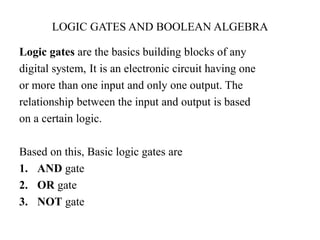
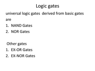
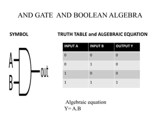
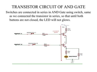
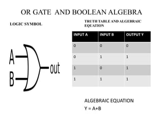
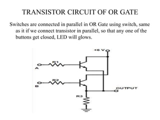
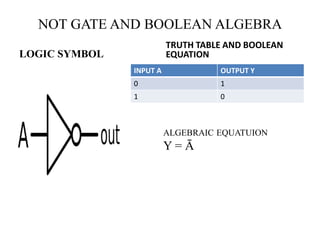
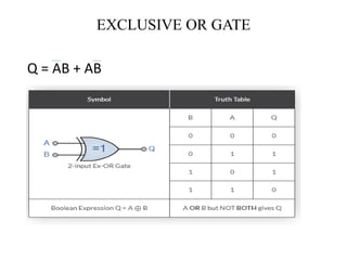
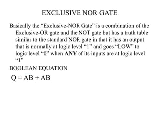
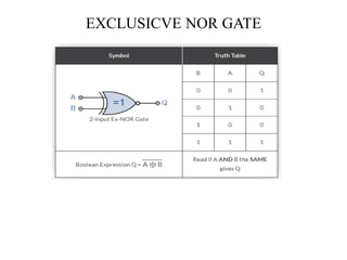
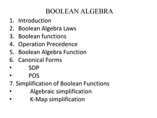
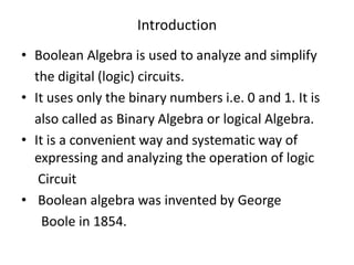
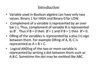
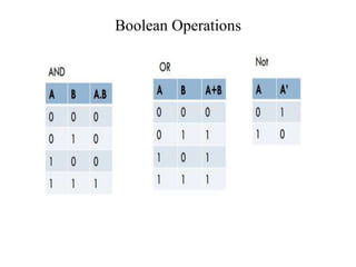
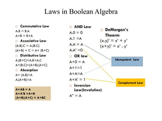
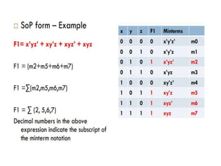
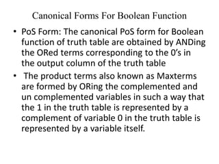
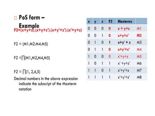
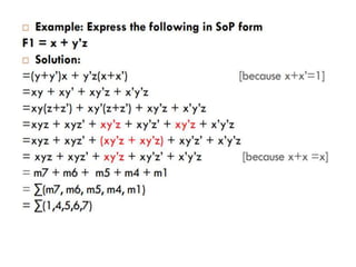
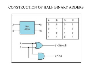
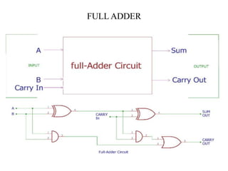
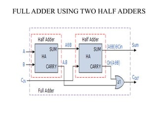
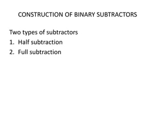
LOGIC GATES AND BOOLEAN ALGEBRA
Logic gates are the basics building blocks of any
digital system, It is an electronic circuit having one
or more than one input and only one output. The
relationship between the input and output is based
on a certain logic.
Based on this, Basic logic gates are
1. AND gate
2. OR gate
3. NOT gate
Logic gates
universal logic gates derived from basic gates
are
1. NAND Gates
2. NOR Gates
Other gates
1. EX-OR Gates
2. EX-NOR Gates
AND GATE AND BOOLEAN ALGEBRA
SYMBOL TRUTH TABLE and ALGEBRAIC EQUATION
Algebraic equation
Y= A.B
INPUT A INPUT B OUTPUT Y
0 0 0
0 1 0
1 0 0
1 1 1
TRANSISTOR CIRCUIT OF AND GATE
Switches are connected in series in AND Gate using switch, same
as we connected the transistor in series, so that until both
buttons are not closed, the LED will not glows.
OR GATE AND BOOLEAN ALGEBRA
LOGIC SYMBOL
TRUTH TABLE AND ALGEBRAIC
EQUATION
ALGEBRAIC EQUATION
Y = A+B
INPUT A INPUT B OUTPUT Y
0 0 0
0 1 1
1 0 1
1 1 1
TRANSISTOR CIRCUIT OF OR GATE
Switches are connected in parallel in OR Gate using switch, same
as it if we connect transistor in parallel, so that any one of the
buttons get closed, LED will glows.
NOT GATE AND BOOLEAN ALGEBRA
LOGIC SYMBOL
TRUTH TABLE AND BOOLEAN
EQUATION
INPUT A OUTPUT Y
0 1
1 0
ALGEBRAIC EQUATUION
Y = Ā
TRANSISTOR CIRCUIT OF NOT GATE
• Initially when the button is open circuited, Transistor wouldn’t allow the
signal to pass through the emitter. So the only path remaining for current to
reach to the ground is collector i.e. through LED. In this case LED glows.
• When we press the button it activates it’s base and maximum current
passes through emitter rather than collector. In this case the LED does not
glows.
NOR GATE
The NOR gate is a digital logic gate that
implements logical NOR - it behaves according to
the truth table to the right. A HIGH output (1)
results if both the inputs to the gate are LOW (0); if
one or both input is HIGH (1), a LOW output (0)
results. NOR is the result of the negation of the OR
operator
X = A + B
INPUT A INPUT B OUTPUT X
0 0 1
0 1 0
1 0 0
1 1 0
NAND GATE
In digital electronics, a NAND gate (NOT-AND) is
a logic gate which produces an output which is
false only if all its inputs are true; thus its output
is complement to that of an AND gate. A LOW (0)
output results only if all the inputs to the gate are
HIGH (1); if any input is LOW (0), a HIGH (1)
output results
Y = A•B
INPUT A INPUT B OUTPUT Y
0 0 1
0 1 1
1 0 1
1 1 0
EXCLUSIVE OR GATE
The “Exclusive OR Gate” is another type of digital logic
gate commonly used in arithmetic operations since it can
be used to give the sum of two binary numbers as well as
error-detection and correction circuits.
The Exclusive-OR Gate function, or Ex-OR for short, is
achieved by combining standard logic gates together to
form more complex gate functions that are used
extensively in building arithmetic logic circuits,
computational logic comparators and error detection
circuits.
EXCLUSIVE OR GATE
Q = AB + AB
EXCLUSIVE NOR GATE
Basically the “Exclusive-NOR Gate” is a combination of the
Exclusive-OR gate and the NOT gate but has a truth table
similar to the standard NOR gate in that it has an output
that is normally at logic level “1” and goes “LOW” to
logic level “0” when ANY of its inputs are at logic level
“1”
BOOLEAN EQUATION
Q = AB + AB
EXCLUSICVE NOR GATE
BOOLEAN ALGEBRA
1. Introduction
2. Boolean Algebra Laws
3. Boolean functions
4. Operation Precedence
5. Boolean Algebra Function
6. Canonical Forms
• SOP
• POS
7. Simplification of Boolean Functions
• Algebraic simplification
• K-Map simplification
Introduction
• Boolean Algebra is used to analyze and simplify
the digital (logic) circuits.
• It uses only the binary numbers i.e. 0 and 1. It is
also called as Binary Algebra or logical Algebra.
• It is a convenient way and systematic way of
expressing and analyzing the operation of logic
Circuit
• Boolean algebra was invented by George
Boole in 1854.
Introduction
• Variable used in Boolean algebra can have only two
values. Binary 1 for HIGH and Binary 0 for LOW.
• Complement of a variable is represented by an over
bar (-). Thus, complement of variable B is represented
as B’ . Thus if B = 0 then B’= 1 and if B = 1 then B’= 0.
• ORing of the variables is represented by a plus (+) sign
between them. For example ORing of A, B, C is
represented as A + B + C.
• Logical ANDing of the two or more variable is
represented by writing a dot between them such as
A.B.C. Sometime the dot may be omitted like ABC.
Boolean Operations
Laws in Boolean Algebra
Boolean Algebraic Function
• A Boolean function can be expressed algebraically with
binary variables, the logic operation symbols, parentheses
and equal sign.
• For a given combination of values of the variables, the
Boolean function can be either 1 or 0.
• Consider for example, the Boolean Function: F1 = x + y’z
The Function F1 is equal to 1 if x is 1 or if both y' and z are
equal to 1; F1 is equal to 0 otherwise.
• The relationship between a function and its binary
variables can be represented in a truth table. To represent a
function in a truth table we need a list of the 2
n combinations of the n binary variables.
• A Boolean function can be transformed from an algebraic
expression into a logic diagram composed of different
Gates
Boolean Algebraic Function
The purpose of Boolean algebra is to facilitate the
analysis and design of digital circuits. It provides a
convenient tool to:
• Express in algebraic form a truth table relationship
between binary variables.
• Express in algebraic form the input-output relationship
of logic diagrams.
• Find simpler circuits for the same function.
• A Boolean function specified by a truth table can be
expressed algebraically in many different ways. Two
ways of forming Boolean expressions
are Canonical and Non Canonical forms.
Canonical Forms For Boolean Function
SOP Form: The canonical SoP form for Boolean
function of truth table are obtained by ORing
the ANDed terms corresponding to the 1’s in
the output column of the truth table
The product terms also known as minterms are
formed by ANDing the complemented and un
complemented variables in such a way that
the 0 in the truth table is represented by a
complement of variable, 1 in the truth table is
represented by a variable itself.
Canonical Forms For Boolean Function
• PoS Form: The canonical PoS form for Boolean
function of truth table are obtained by ANDing
the ORed terms corresponding to the 0’s in
the output column of the truth table
• The product terms also known as Maxterms
are formed by ORing the complemented and
un complemented variables in such a way that
the 1 in the truth table is represented by a
complement of variable 0 in the truth table is
represented by a variable itself.
Canonical Forms - Exercises
Exercise 1: Express G(A,B,C)=A.B.C + A’.B + B’.C in
SoP form.
Exercise 2: Express F(A,B,C)=A.B’ + B’.C in PoS
form
Simplification of Boolean functions
• Algebraic simplification
• K-Map simplification
Algebraic simplification
Simplify:
C + (BC)’ =C + (BC)’ Original Expression
=C + (B’ + C’) DeMorgan's Law.
=(C + C’) + B’ Commutative, Associative Laws.
=1 + B’ Complement Law.
=1 Identity Law.
Algebraic simplification
Exercise 3: Using the theorems and laws of
Boolean Algebra, reduce the following
functions F1(A,B,C,D) = ∑(0,1,2,3,6,7,14,15)
Exercise 4: Using the theorems and laws of
Boolean Algebra, reduce the following
functions F1(X,Y,Z) = ∏(0,1,4,5,7)
Using the Theorems and Laws of Boolean
algebra, Prove the following. (A+B) .(A+A’B’).C
+ (A’.(B+C’))’ + A’.B + A.B.C = A+B+C
BINARY ADDERS
A digital binary adder is a digital device that adds two
binary numbers and gives its sum in binary format.
Application of binary adders
• Digital adders are mostly used in computer’s ALU
(Arithmetic logic unit) to compute addition.
• Digital calculators use adders for arithmetic addition.
• Micro controllers use adders in arithmetic additions,
• PC (program counter) and timers
• Every device that uses some kind of increment or
arithmetic process contains adders.
CONSTRUCTION OF BINARY ADDERS
Two types of ADDERS
1. Half ADDERS
2. Full ADDERS
CONSTRUCTION OF HALF BINARY ADDERS
FULL ADDER
FULL ADDER USING TWO HALF ADDERS
CONSTRUCTION OF BINARY SUBTRACTORS
Two types of subtractors
1. Half subtraction
2. Full subtraction

Lecture 03 Logic gate and boolean algebra.pdf

  • 1.
    LOGIC GATES ANDBOOLEAN ALGEBRA Logic gates are the basics building blocks of any digital system, It is an electronic circuit having one or more than one input and only one output. The relationship between the input and output is based on a certain logic. Based on this, Basic logic gates are 1. AND gate 2. OR gate 3. NOT gate
  • 2.
    Logic gates universal logicgates derived from basic gates are 1. NAND Gates 2. NOR Gates Other gates 1. EX-OR Gates 2. EX-NOR Gates
  • 3.
    AND GATE ANDBOOLEAN ALGEBRA SYMBOL TRUTH TABLE and ALGEBRAIC EQUATION Algebraic equation Y= A.B INPUT A INPUT B OUTPUT Y 0 0 0 0 1 0 1 0 0 1 1 1
  • 4.
    TRANSISTOR CIRCUIT OFAND GATE Switches are connected in series in AND Gate using switch, same as we connected the transistor in series, so that until both buttons are not closed, the LED will not glows.
  • 5.
    OR GATE ANDBOOLEAN ALGEBRA LOGIC SYMBOL TRUTH TABLE AND ALGEBRAIC EQUATION ALGEBRAIC EQUATION Y = A+B INPUT A INPUT B OUTPUT Y 0 0 0 0 1 1 1 0 1 1 1 1
  • 6.
    TRANSISTOR CIRCUIT OFOR GATE Switches are connected in parallel in OR Gate using switch, same as it if we connect transistor in parallel, so that any one of the buttons get closed, LED will glows.
  • 7.
    NOT GATE ANDBOOLEAN ALGEBRA LOGIC SYMBOL TRUTH TABLE AND BOOLEAN EQUATION INPUT A OUTPUT Y 0 1 1 0 ALGEBRAIC EQUATUION Y = Ā
  • 8.
    TRANSISTOR CIRCUIT OFNOT GATE • Initially when the button is open circuited, Transistor wouldn’t allow the signal to pass through the emitter. So the only path remaining for current to reach to the ground is collector i.e. through LED. In this case LED glows. • When we press the button it activates it’s base and maximum current passes through emitter rather than collector. In this case the LED does not glows.
  • 9.
    NOR GATE The NORgate is a digital logic gate that implements logical NOR - it behaves according to the truth table to the right. A HIGH output (1) results if both the inputs to the gate are LOW (0); if one or both input is HIGH (1), a LOW output (0) results. NOR is the result of the negation of the OR operator X = A + B INPUT A INPUT B OUTPUT X 0 0 1 0 1 0 1 0 0 1 1 0
  • 10.
    NAND GATE In digitalelectronics, a NAND gate (NOT-AND) is a logic gate which produces an output which is false only if all its inputs are true; thus its output is complement to that of an AND gate. A LOW (0) output results only if all the inputs to the gate are HIGH (1); if any input is LOW (0), a HIGH (1) output results Y = A•B INPUT A INPUT B OUTPUT Y 0 0 1 0 1 1 1 0 1 1 1 0
  • 11.
    EXCLUSIVE OR GATE The“Exclusive OR Gate” is another type of digital logic gate commonly used in arithmetic operations since it can be used to give the sum of two binary numbers as well as error-detection and correction circuits. The Exclusive-OR Gate function, or Ex-OR for short, is achieved by combining standard logic gates together to form more complex gate functions that are used extensively in building arithmetic logic circuits, computational logic comparators and error detection circuits.
  • 12.
  • 13.
    EXCLUSIVE NOR GATE Basicallythe “Exclusive-NOR Gate” is a combination of the Exclusive-OR gate and the NOT gate but has a truth table similar to the standard NOR gate in that it has an output that is normally at logic level “1” and goes “LOW” to logic level “0” when ANY of its inputs are at logic level “1” BOOLEAN EQUATION Q = AB + AB
  • 14.
  • 15.
    BOOLEAN ALGEBRA 1. Introduction 2.Boolean Algebra Laws 3. Boolean functions 4. Operation Precedence 5. Boolean Algebra Function 6. Canonical Forms • SOP • POS 7. Simplification of Boolean Functions • Algebraic simplification • K-Map simplification
  • 16.
    Introduction • Boolean Algebrais used to analyze and simplify the digital (logic) circuits. • It uses only the binary numbers i.e. 0 and 1. It is also called as Binary Algebra or logical Algebra. • It is a convenient way and systematic way of expressing and analyzing the operation of logic Circuit • Boolean algebra was invented by George Boole in 1854.
  • 17.
    Introduction • Variable usedin Boolean algebra can have only two values. Binary 1 for HIGH and Binary 0 for LOW. • Complement of a variable is represented by an over bar (-). Thus, complement of variable B is represented as B’ . Thus if B = 0 then B’= 1 and if B = 1 then B’= 0. • ORing of the variables is represented by a plus (+) sign between them. For example ORing of A, B, C is represented as A + B + C. • Logical ANDing of the two or more variable is represented by writing a dot between them such as A.B.C. Sometime the dot may be omitted like ABC.
  • 18.
  • 19.
  • 20.
    Boolean Algebraic Function •A Boolean function can be expressed algebraically with binary variables, the logic operation symbols, parentheses and equal sign. • For a given combination of values of the variables, the Boolean function can be either 1 or 0. • Consider for example, the Boolean Function: F1 = x + y’z The Function F1 is equal to 1 if x is 1 or if both y' and z are equal to 1; F1 is equal to 0 otherwise. • The relationship between a function and its binary variables can be represented in a truth table. To represent a function in a truth table we need a list of the 2 n combinations of the n binary variables. • A Boolean function can be transformed from an algebraic expression into a logic diagram composed of different Gates
  • 21.
  • 22.
    Boolean Algebraic Function Thepurpose of Boolean algebra is to facilitate the analysis and design of digital circuits. It provides a convenient tool to: • Express in algebraic form a truth table relationship between binary variables. • Express in algebraic form the input-output relationship of logic diagrams. • Find simpler circuits for the same function. • A Boolean function specified by a truth table can be expressed algebraically in many different ways. Two ways of forming Boolean expressions are Canonical and Non Canonical forms.
  • 23.
    Canonical Forms ForBoolean Function SOP Form: The canonical SoP form for Boolean function of truth table are obtained by ORing the ANDed terms corresponding to the 1’s in the output column of the truth table The product terms also known as minterms are formed by ANDing the complemented and un complemented variables in such a way that the 0 in the truth table is represented by a complement of variable, 1 in the truth table is represented by a variable itself.
  • 25.
    Canonical Forms ForBoolean Function • PoS Form: The canonical PoS form for Boolean function of truth table are obtained by ANDing the ORed terms corresponding to the 0’s in the output column of the truth table • The product terms also known as Maxterms are formed by ORing the complemented and un complemented variables in such a way that the 1 in the truth table is represented by a complement of variable 0 in the truth table is represented by a variable itself.
  • 28.
    Canonical Forms -Exercises Exercise 1: Express G(A,B,C)=A.B.C + A’.B + B’.C in SoP form. Exercise 2: Express F(A,B,C)=A.B’ + B’.C in PoS form
  • 29.
    Simplification of Booleanfunctions • Algebraic simplification • K-Map simplification
  • 30.
  • 32.
    Simplify: C + (BC)’=C + (BC)’ Original Expression =C + (B’ + C’) DeMorgan's Law. =(C + C’) + B’ Commutative, Associative Laws. =1 + B’ Complement Law. =1 Identity Law.
  • 33.
    Algebraic simplification Exercise 3:Using the theorems and laws of Boolean Algebra, reduce the following functions F1(A,B,C,D) = ∑(0,1,2,3,6,7,14,15) Exercise 4: Using the theorems and laws of Boolean Algebra, reduce the following functions F1(X,Y,Z) = ∏(0,1,4,5,7) Using the Theorems and Laws of Boolean algebra, Prove the following. (A+B) .(A+A’B’).C + (A’.(B+C’))’ + A’.B + A.B.C = A+B+C
  • 34.
    BINARY ADDERS A digitalbinary adder is a digital device that adds two binary numbers and gives its sum in binary format. Application of binary adders • Digital adders are mostly used in computer’s ALU (Arithmetic logic unit) to compute addition. • Digital calculators use adders for arithmetic addition. • Micro controllers use adders in arithmetic additions, • PC (program counter) and timers • Every device that uses some kind of increment or arithmetic process contains adders.
  • 35.
    CONSTRUCTION OF BINARYADDERS Two types of ADDERS 1. Half ADDERS 2. Full ADDERS
  • 36.
    CONSTRUCTION OF HALFBINARY ADDERS
  • 37.
  • 38.
    FULL ADDER USINGTWO HALF ADDERS
  • 39.
    CONSTRUCTION OF BINARYSUBTRACTORS Two types of subtractors 1. Half subtraction 2. Full subtraction