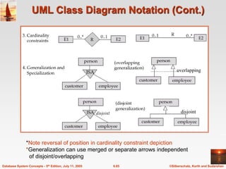
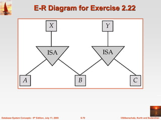
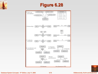
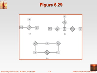
Database System Concepts, 5th Ed.
©Silberschatz, Korth and Sudarshan
See www.db-book.com for conditions on re-use
Chapter 6: Entity-Relationship Model
©Silberschatz, Korth and Sudarshan
6.2
Database System Concepts - 5th Edition, July 11, 2005
Chapter 6: Entity-Relationship Model
 Design Process
 Modeling
 Constraints
 E-R Diagram
 Design Issues
 Weak Entity Sets
 Extended E-R Features
 Design of the Bank Database
 Reduction to Relation Schemas
 Database Design
 UML
©Silberschatz, Korth and Sudarshan
6.3
Database System Concepts - 5th Edition, July 11, 2005
Modeling
 A database can be modeled as:
 a collection of entities,
 relationship among entities.
 An entity is an object that exists and is distinguishable from other
objects.
 Example: specific person, company, event, plant
 Entities have attributes
 Example: people have names and addresses
 An entity set is a set of entities of the same type that share the same
properties.
 Example: set of all persons, companies, trees, holidays
©Silberschatz, Korth and Sudarshan
6.4
Database System Concepts - 5th Edition, July 11, 2005
Entity Sets customer and loan
customer_id customer_ customer_ customer_ loan_ amount
name street city number
©Silberschatz, Korth and Sudarshan
6.5
Database System Concepts - 5th Edition, July 11, 2005
Relationship Sets
 A relationship is an association among several entities
Example:
Hayes depositor A-102
customer entity relationship set account entity
 A relationship set is a mathematical relation among n  2 entities, each
taken from entity sets
{(e1, e2, … en) | e1  E1, e2  E2, …, en  En}
where (e1, e2, …, en) is a relationship
 Example:
(Hayes, A-102)  depositor
©Silberschatz, Korth and Sudarshan
6.6
Database System Concepts - 5th Edition, July 11, 2005
Relationship Set borrower
©Silberschatz, Korth and Sudarshan
6.7
Database System Concepts - 5th Edition, July 11, 2005
Relationship Sets (Cont.)
 An attribute can also be property of a relationship set.
 For instance, the depositor relationship set between entity sets
customer and account may have the attribute access-date
©Silberschatz, Korth and Sudarshan
6.8
Database System Concepts - 5th Edition, July 11, 2005
Degree of a Relationship Set
 Refers to number of entity sets that participate in a relationship
set.
 Relationship sets that involve two entity sets are binary (or
degree two). Generally, most relationship sets in a database
system are binary.
 Relationship sets may involve more than two entity sets.
 Relationships between more than two entity sets are rare. Most
relationships are binary. (More on this later.)
Example: Suppose employees of a bank may have jobs
(responsibilities) at multiple branches, with different jobs at
different branches. Then there is a ternary relationship set
between entity sets employee, job, and branch
©Silberschatz, Korth and Sudarshan
6.9
Database System Concepts - 5th Edition, July 11, 2005
Attributes
 An entity is represented by a set of attributes, that is descriptive
properties possessed by all members of an entity set.
 Domain – the set of permitted values for each attribute
 Attribute types:
 Simple and composite attributes.
 Single-valued and multi-valued attributes
 Example: multivalued attribute: phone_numbers
 Derived attributes
 Can be computed from other attributes
 Example: age, given date_of_birth
Example:
customer = (customer_id, customer_name,
customer_street, customer_city )
loan = (loan_number, amount )
©Silberschatz, Korth and Sudarshan
6.10
Database System Concepts - 5th Edition, July 11, 2005
Composite Attributes
©Silberschatz, Korth and Sudarshan
6.11
Database System Concepts - 5th Edition, July 11, 2005
Mapping Cardinality Constraints
 Express the number of entities to which another entity can be
associated via a relationship set.
 Most useful in describing binary relationship sets.
 For a binary relationship set the mapping cardinality must be one of
the following types:
 One to one
 One to many
 Many to one
 Many to many
©Silberschatz, Korth and Sudarshan
6.12
Database System Concepts - 5th Edition, July 11, 2005
Mapping Cardinalities
One to one One to many
Note: Some elements in A and B may not be mapped to any
elements in the other set
©Silberschatz, Korth and Sudarshan
6.13
Database System Concepts - 5th Edition, July 11, 2005
Mapping Cardinalities
Many to one Many to many
Note: Some elements in A and B may not be mapped to any
elements in the other set
©Silberschatz, Korth and Sudarshan
6.14
Database System Concepts - 5th Edition, July 11, 2005
Keys
 A super key of an entity set is a set of one or more attributes
whose values uniquely determine each entity.
 A candidate key of an entity set is a minimal super key
 Customer_id is candidate key of customer
 account_number is candidate key of account
 Although several candidate keys may exist, one of the candidate
keys is selected to be the primary key.
©Silberschatz, Korth and Sudarshan
6.15
Database System Concepts - 5th Edition, July 11, 2005
Keys for Relationship Sets
 The combination of primary keys of the participating entity sets forms a
super key of a relationship set.
 (customer_id, account_number) is the super key of depositor
 NOTE: this means a pair of entity sets can have at most one
relationship in a particular relationship set.
 Example: if we wish to track all access_dates to each account by
each customer, we cannot assume a relationship for each
access. We can use a multivalued attribute though
 Must consider the mapping cardinality of the relationship set when
deciding the what are the candidate keys
 Need to consider semantics of relationship set in selecting the primary
key in case of more than one candidate key
©Silberschatz, Korth and Sudarshan
6.16
Database System Concepts - 5th Edition, July 11, 2005
E-R Diagrams
 Rectangles represent entity sets.
 Diamonds represent relationship sets.
 Lines link attributes to entity sets and entity sets to relationship sets.
 Ellipses represent attributes
 Double ellipses represent multivalued attributes.
 Dashed ellipses denote derived attributes.
 Underline indicates primary key attributes (will study later)
©Silberschatz, Korth and Sudarshan
6.17
Database System Concepts - 5th Edition, July 11, 2005
E-R Diagram With Composite, Multivalued, and
Derived Attributes
©Silberschatz, Korth and Sudarshan
6.18
Database System Concepts - 5th Edition, July 11, 2005
Relationship Sets with Attributes
©Silberschatz, Korth and Sudarshan
6.19
Database System Concepts - 5th Edition, July 11, 2005
Roles
 Entity sets of a relationship need not be distinct
 The labels “manager” and “worker” are called roles; they specify how
employee entities interact via the works_for relationship set.
 Roles are indicated in E-R diagrams by labeling the lines that connect
diamonds to rectangles.
 Role labels are optional, and are used to clarify semantics of the
relationship
©Silberschatz, Korth and Sudarshan
6.20
Database System Concepts - 5th Edition, July 11, 2005
Cardinality Constraints
 We express cardinality constraints by drawing either a directed line (),
signifying “one,” or an undirected line (—), signifying “many,” between
the relationship set and the entity set.
 One-to-one relationship:
 A customer is associated with at most one loan via the relationship
borrower
 A loan is associated with at most one customer via borrower
©Silberschatz, Korth and Sudarshan
6.21
Database System Concepts - 5th Edition, July 11, 2005
One-To-Many Relationship
 In the one-to-many relationship a loan is associated with at most one
customer via borrower, a customer is associated with several (including
0) loans via borrower
©Silberschatz, Korth and Sudarshan
6.22
Database System Concepts - 5th Edition, July 11, 2005
Many-To-One Relationships
 In a many-to-one relationship a loan is associated with several
(including 0) customers via borrower, a customer is associated with at
most one loan via borrower
©Silberschatz, Korth and Sudarshan
6.23
Database System Concepts - 5th Edition, July 11, 2005
Many-To-Many Relationship
 A customer is associated with several (possibly 0) loans via
borrower
 A loan is associated with several (possibly 0) customers via
borrower
©Silberschatz, Korth and Sudarshan
6.24
Database System Concepts - 5th Edition, July 11, 2005
Participation of an Entity Set in a
Relationship Set
 Total participation (indicated by double line): every entity in the entity set
participates in at least one relationship in the relationship set
 E.g. participation of loan in borrower is total
 every loan must have a customer associated to it via borrower
 Partial participation: some entities may not participate in any relationship in
the relationship set
 Example: participation of customer in borrower is partial
©Silberschatz, Korth and Sudarshan
6.25
Database System Concepts - 5th Edition, July 11, 2005
Alternative Notation for Cardinality Limits
 Cardinality limits can also express participation constraints
©Silberschatz, Korth and Sudarshan
6.26
Database System Concepts - 5th Edition, July 11, 2005
E-R Diagram with a Ternary Relationship
©Silberschatz, Korth and Sudarshan
6.27
Database System Concepts - 5th Edition, July 11, 2005
Cardinality Constraints on Ternary
Relationship
 We allow at most one arrow out of a ternary (or greater degree) relationship
to indicate a cardinality constraint
 E.g. an arrow from works_on to job indicates each employee works on at
most one job at any branch.
 If there is more than one arrow, there are two ways of defining the meaning.
 E.g a ternary relationship R between A, B and C with arrows to B and C
could mean
1. each A entity is associated with a unique entity from B and C or
2. each pair of entities from (A, B) is associated with a unique C entity,
and each pair (A, C) is associated with a unique B
 Each alternative has been used in different formalisms
 To avoid confusion we outlaw more than one arrow
©Silberschatz, Korth and Sudarshan
6.28
Database System Concepts - 5th Edition, July 11, 2005
Design Issues
 Use of entity sets vs. attributes
Choice mainly depends on the structure of the enterprise being
modeled, and on the semantics associated with the attribute in
question.
 Use of entity sets vs. relationship sets
Possible guideline is to designate a relationship set to describe an
action that occurs between entities
 Binary versus n-ary relationship sets
Although it is possible to replace any nonbinary (n-ary, for n > 2)
relationship set by a number of distinct binary relationship sets, a
n-ary relationship set shows more clearly that several entities
participate in a single relationship.
 Placement of relationship attributes
©Silberschatz, Korth and Sudarshan
6.29
Database System Concepts - 5th Edition, July 11, 2005
Binary Vs. Non-Binary Relationships
 Some relationships that appear to be non-binary may be better
represented using binary relationships
 E.g. A ternary relationship parents, relating a child to his/her father
and mother, is best replaced by two binary relationships, father
and mother
 Using two binary relationships allows partial information (e.g.
only mother being know)
 But there are some relationships that are naturally non-binary
 Example: works_on
©Silberschatz, Korth and Sudarshan
6.30
Database System Concepts - 5th Edition, July 11, 2005
Converting Non-Binary Relationships to
Binary Form
 In general, any non-binary relationship can be represented using binary relationships
by creating an artificial entity set.
 Replace R between entity sets A, B and C by an entity set E, and three
relationship sets:
1. RA, relating E and A 2.RB, relating E and B
3. RC, relating E and C
 Create a special identifying attribute for E
 Add any attributes of R to E
 For each relationship (ai , bi , ci) in R, create
1. a new entity ei in the entity set E 2. add (ei , ai ) to RA
3. add (ei , bi ) to RB 4. add (ei , ci ) to RC
©Silberschatz, Korth and Sudarshan
6.31
Database System Concepts - 5th Edition, July 11, 2005
Converting Non-Binary Relationships
(Cont.)
 Also need to translate constraints
 Translating all constraints may not be possible
 There may be instances in the translated schema that
cannot correspond to any instance of R
 Exercise: add constraints to the relationships RA, RB and
RC to ensure that a newly created entity corresponds to
exactly one entity in each of entity sets A, B and C
 We can avoid creating an identifying attribute by making E a
weak entity set (described shortly) identified by the three
relationship sets
©Silberschatz, Korth and Sudarshan
6.32
Database System Concepts - 5th Edition, July 11, 2005
Mapping Cardinalities affect ER Design
 Can make access-date an attribute of account, instead of a relationship
attribute, if each account can have only one customer
 That is, the relationship from account to customer is many to one, or
equivalently, customer to account is one to many
Database System Concepts, 5th Ed.
©Silberschatz, Korth and Sudarshan
See www.db-book.com for conditions on re-use
How about doing an ER design
interactively on the board?
Suggest an application to be modeled.
©Silberschatz, Korth and Sudarshan
6.34
Database System Concepts - 5th Edition, July 11, 2005
Weak Entity Sets
 An entity set that does not have a primary key is referred to as a weak
entity set.
 The existence of a weak entity set depends on the existence of a
identifying entity set
 it must relate to the identifying entity set via a total, one-to-many
relationship set from the identifying to the weak entity set
 Identifying relationship depicted using a double diamond
 The discriminator (or partial key) of a weak entity set is the set of
attributes that distinguishes among all the entities of a weak entity set.
 The primary key of a weak entity set is formed by the primary key of the
strong entity set on which the weak entity set is existence dependent,
plus the weak entity set’s discriminator.
©Silberschatz, Korth and Sudarshan
6.35
Database System Concepts - 5th Edition, July 11, 2005
Weak Entity Sets (Cont.)
 We depict a weak entity set by double rectangles.
 We underline the discriminator of a weak entity set with a dashed
line.
 payment_number – discriminator of the payment entity set
 Primary key for payment – (loan_number, payment_number)
©Silberschatz, Korth and Sudarshan
6.36
Database System Concepts - 5th Edition, July 11, 2005
Weak Entity Sets (Cont.)
 Note: the primary key of the strong entity set is not explicitly stored
with the weak entity set, since it is implicit in the identifying
relationship.
 If loan_number were explicitly stored, payment could be made a
strong entity, but then the relationship between payment and loan
would be duplicated by an implicit relationship defined by the
attribute loan_number common to payment and loan
©Silberschatz, Korth and Sudarshan
6.37
Database System Concepts - 5th Edition, July 11, 2005
More Weak Entity Set Examples
 In a university, a course is a strong entity and a course_offering can
be modeled as a weak entity
 The discriminator of course_offering would be semester (including
year) and section_number (if there is more than one section)
 If we model course_offering as a strong entity we would model
course_number as an attribute.
Then the relationship with course would be implicit in the
course_number attribute
©Silberschatz, Korth and Sudarshan
6.38
Database System Concepts - 5th Edition, July 11, 2005
Extended E-R Features: Specialization
 Top-down design process; we designate subgroupings within an entity set
that are distinctive from other entities in the set.
 These subgroupings become lower-level entity sets that have attributes or
participate in relationships that do not apply to the higher-level entity set.
 Depicted by a triangle component labeled ISA (E.g. customer “is a”
person).
 Attribute inheritance – a lower-level entity set inherits all the attributes
and relationship participation of the higher-level entity set to which it is
linked.
©Silberschatz, Korth and Sudarshan
6.39
Database System Concepts - 5th Edition, July 11, 2005
Specialization Example
©Silberschatz, Korth and Sudarshan
6.40
Database System Concepts - 5th Edition, July 11, 2005
Extended ER Features: Generalization
 A bottom-up design process – combine a number of entity sets
that share the same features into a higher-level entity set.
 Specialization and generalization are simple inversions of each
other; they are represented in an E-R diagram in the same way.
 The terms specialization and generalization are used
interchangeably.
©Silberschatz, Korth and Sudarshan
6.41
Database System Concepts - 5th Edition, July 11, 2005
Specialization and Generalization (Cont.)
 Can have multiple specializations of an entity set based on different
features.
 E.g. permanent_employee vs. temporary_employee, in addition to
officer vs. secretary vs. teller
 Each particular employee would be
 a member of one of permanent_employee or temporary_employee,
 and also a member of one of officer, secretary, or teller
 The ISA relationship also referred to as superclass - subclass
relationship
©Silberschatz, Korth and Sudarshan
6.42
Database System Concepts - 5th Edition, July 11, 2005
Design Constraints on a
Specialization/Generalization
 Constraint on which entities can be members of a given lower-level
entity set.
 condition-defined
 Example: all customers over 65 years are members of senior-
citizen entity set; senior-citizen ISA person.
 user-defined
 Constraint on whether or not entities may belong to more than one
lower-level entity set within a single generalization.
 Disjoint
 an entity can belong to only one lower-level entity set
 Noted in E-R diagram by writing disjoint next to the ISA
triangle
 Overlapping
 an entity can belong to more than one lower-level entity set
©Silberschatz, Korth and Sudarshan
6.43
Database System Concepts - 5th Edition, July 11, 2005
Design Constraints on a
Specialization/Generalization (Cont.)
 Completeness constraint -- specifies whether or not an
entity in the higher-level entity set must belong to at least one
of the lower-level entity sets within a generalization.
 total : an entity must belong to one of the lower-level
entity sets
 partial: an entity need not belong to one of the lower-level
entity sets
©Silberschatz, Korth and Sudarshan
6.44
Database System Concepts - 5th Edition, July 11, 2005
Aggregation
 Consider the ternary relationship works_on, which we saw earlier
 Suppose we want to record managers for tasks performed by an
employee at a branch
©Silberschatz, Korth and Sudarshan
6.45
Database System Concepts - 5th Edition, July 11, 2005
Aggregation (Cont.)
 Relationship sets works_on and manages represent overlapping information
 Every manages relationship corresponds to a works_on relationship
 However, some works_on relationships may not correspond to any
manages relationships
 So we can’t discard the works_on relationship
 Eliminate this redundancy via aggregation
 Treat relationship as an abstract entity
 Allows relationships between relationships
 Abstraction of relationship into new entity
 Without introducing redundancy, the following diagram represents:
 An employee works on a particular job at a particular branch
 An employee, branch, job combination may have an associated manager
©Silberschatz, Korth and Sudarshan
6.46
Database System Concepts - 5th Edition, July 11, 2005
E-R Diagram With Aggregation
©Silberschatz, Korth and Sudarshan
6.47
Database System Concepts - 5th Edition, July 11, 2005
E-R Design Decisions
 The use of an attribute or entity set to represent an object.
 Whether a real-world concept is best expressed by an entity set or
a relationship set.
 The use of a ternary relationship versus a pair of binary
relationships.
 The use of a strong or weak entity set.
 The use of specialization/generalization – contributes to modularity
in the design.
 The use of aggregation – can treat the aggregate entity set as a
single unit without concern for the details of its internal structure.
©Silberschatz, Korth and Sudarshan
6.48
Database System Concepts - 5th Edition, July 11, 2005
E-R Diagram for a Banking Enterprise
Database System Concepts, 5th Ed.
©Silberschatz, Korth and Sudarshan
See www.db-book.com for conditions on re-use
How about doing another ER design
interactively on the board?
©Silberschatz, Korth and Sudarshan
6.50
Database System Concepts - 5th Edition, July 11, 2005
Summary of Symbols Used in E-R Notation
©Silberschatz, Korth and Sudarshan
6.51
Database System Concepts - 5th Edition, July 11, 2005
Summary of Symbols (Cont.)
©Silberschatz, Korth and Sudarshan
6.52
Database System Concepts - 5th Edition, July 11, 2005
Reduction to Relation Schemas
 Primary keys allow entity sets and relationship sets to be
expressed uniformly as relation schemas that represent the
contents of the database.
 A database which conforms to an E-R diagram can be
represented by a collection of schemas.
 For each entity set and relationship set there is a unique
schema that is assigned the name of the corresponding entity
set or relationship set.
 Each schema has a number of columns (generally
corresponding to attributes), which have unique names.
©Silberschatz, Korth and Sudarshan
6.53
Database System Concepts - 5th Edition, July 11, 2005
Representing Entity Sets as Schemas
 A strong entity set reduces to a schema with the same attributes.
 A weak entity set becomes a table that includes a column for the
primary key of the identifying strong entity set
payment =
( loan_number, payment_number, payment_date, payment_amount )
©Silberschatz, Korth and Sudarshan
6.54
Database System Concepts - 5th Edition, July 11, 2005
Representing Relationship Sets as
Schemas
 A many-to-many relationship set is represented as a schema with
attributes for the primary keys of the two participating entity sets,
and any descriptive attributes of the relationship set.
 Example: schema for relationship set borrower
borrower = (customer_id, loan_number )
©Silberschatz, Korth and Sudarshan
6.55
Database System Concepts - 5th Edition, July 11, 2005
Redundancy of Schemas
 Many-to-one and one-to-many relationship sets that are total on the
many-side can be represented by adding an extra attribute to the
“many” side, containing the primary key of the “one” side
 Example: Instead of creating a schema for relationship set
account_branch, add an attribute branch_name to the schema
arising from entity set account
©Silberschatz, Korth and Sudarshan
6.56
Database System Concepts - 5th Edition, July 11, 2005
Redundancy of Schemas (Cont.)
 For one-to-one relationship sets, either side can be chosen to act as the
“many” side
 That is, extra attribute can be added to either of the tables
corresponding to the two entity sets
 If participation is partial on the “many” side, replacing a schema by an
extra attribute in the schema corresponding to the “many” side could
result in null values
 The schema corresponding to a relationship set linking a weak entity set
to its identifying strong entity set is redundant.
 Example: The payment schema already contains the attributes that
would appear in the loan_payment schema (i.e., loan_number and
payment_number).
©Silberschatz, Korth and Sudarshan
6.57
Database System Concepts - 5th Edition, July 11, 2005
Composite and Multivalued Attributes
 Composite attributes are flattened out by creating a separate attribute for
each component attribute
 Example: given entity set customer with composite attribute name with
component attributes first_name and last_name the schema
corresponding to the entity set has two attributes
name.first_name and name.last_name
 A multivalued attribute M of an entity E is represented by a separate
schema EM
 Schema EM has attributes corresponding to the primary key of E and
an attribute corresponding to multivalued attribute M
 Example: Multivalued attribute dependent_names of employee is
represented by a schema:
employee_dependent_names = ( employee_id, dname)
 Each value of the multivalued attribute maps to a separate tuple of the
relation on schema EM
 For example, an employee entity with primary key 123-45-6789
and dependents Jack and Jane maps to two tuples:
(123-45-6789 , Jack) and (123-45-6789 , Jane)
©Silberschatz, Korth and Sudarshan
6.58
Database System Concepts - 5th Edition, July 11, 2005
Representing Specialization via
Schemas
 Method 1:
 Form a schema for the higher-level entity
 Form a schema for each lower-level entity set, include primary
key of higher-level entity set and local attributes
schema attributes
person name, street, city
customer name, credit_rating
employee name, salary
 Drawback: getting information about, an employee requires
accessing two relations, the one corresponding to the low-level
schema and the one corresponding to the high-level schema
©Silberschatz, Korth and Sudarshan
6.59
Database System Concepts - 5th Edition, July 11, 2005
Representing Specialization as Schemas
(Cont.)
 Method 2:
 Form a schema for each entity set with all local and inherited attributes
schema attributes
person name, street, city
customer name, street, city, credit_rating
employee name, street, city, salary
 If specialization is total, the schema for the generalized entity set
(person) not required to store information
 Can be defined as a “view” relation containing union of specialization
relations
 But explicit schema may still be needed for foreign key constraints
 Drawback: street and city may be stored redundantly for people who are
both customers and employees
©Silberschatz, Korth and Sudarshan
6.60
Database System Concepts - 5th Edition, July 11, 2005
Schemas Corresponding to Aggregation
 To represent aggregation, create a schema containing
 primary key of the aggregated relationship,
 the primary key of the associated entity set
 any descriptive attributes
©Silberschatz, Korth and Sudarshan
6.61
Database System Concepts - 5th Edition, July 11, 2005
Schemas Corresponding to
Aggregation (Cont.)
 For example, to represent aggregation manages between
relationship works_on and entity set manager, create a schema
manages (employee_id, branch_name, title, manager_name)
 Schema works_on is redundant provided we are willing to store null
values for attribute manager_name in relation on schema manages
©Silberschatz, Korth and Sudarshan
6.62
Database System Concepts - 5th Edition, July 11, 2005
UML
 UML: Unified Modeling Language
 UML has many components to graphically model different aspects of an
entire software system
 UML Class Diagrams correspond to E-R Diagram, but several
differences.
©Silberschatz, Korth and Sudarshan
6.63
Database System Concepts - 5th Edition, July 11, 2005
Summary of UML Class Diagram Notation
©Silberschatz, Korth and Sudarshan
6.64
Database System Concepts - 5th Edition, July 11, 2005
UML Class Diagrams (Cont.)
 Entity sets are shown as boxes, and attributes are shown within the
box, rather than as separate ellipses in E-R diagrams.
 Binary relationship sets are represented in UML by just drawing a line
connecting the entity sets. The relationship set name is written adjacent
to the line.
 The role played by an entity set in a relationship set may also be
specified by writing the role name on the line, adjacent to the entity set.
 The relationship set name may alternatively be written in a box, along
with attributes of the relationship set, and the box is connected, using a
dotted line, to the line depicting the relationship set.
 Non-binary relationships drawn using diamonds, just as in ER
diagrams
©Silberschatz, Korth and Sudarshan
6.65
Database System Concepts - 5th Edition, July 11, 2005
UML Class Diagram Notation (Cont.)
*Note reversal of position in cardinality constraint depiction
*Generalization can use merged or separate arrows independent
of disjoint/overlapping
overlapping
disjoint
©Silberschatz, Korth and Sudarshan
6.66
Database System Concepts - 5th Edition, July 11, 2005
UML Class Diagrams (Contd.)
 Cardinality constraints are specified in the form l..h, where l
denotes the minimum and h the maximum number of
relationships an entity can participate in.
 Beware: the positioning of the constraints is exactly the reverse
of the positioning of constraints in E-R diagrams.
 The constraint 0..* on the E2 side and 0..1 on the E1 side means
that each E2 entity can participate in at most one relationship,
whereas each E1 entity can participate in many relationships; in
other words, the relationship is many to one from E2 to E1.
 Single values, such as 1 or * may be written on edges; The
single value 1 on an edge is treated as equivalent to 1..1, while *
is equivalent to 0..*.
Database System Concepts, 5th Ed.
©Silberschatz, Korth and Sudarshan
See www.db-book.com for conditions on re-use
End of Chapter 2
©Silberschatz, Korth and Sudarshan
6.68
Database System Concepts - 5th Edition, July 11, 2005
E-R Diagram for Exercise 2.10
©Silberschatz, Korth and Sudarshan
6.69
Database System Concepts - 5th Edition, July 11, 2005
E-R Diagram for Exercise 2.15
©Silberschatz, Korth and Sudarshan
6.70
Database System Concepts - 5th Edition, July 11, 2005
E-R Diagram for Exercise 2.22
©Silberschatz, Korth and Sudarshan
6.71
Database System Concepts - 5th Edition, July 11, 2005
E-R Diagram for Exercise 2.15
©Silberschatz, Korth and Sudarshan
6.72
Database System Concepts - 5th Edition, July 11, 2005
Existence Dependencies
 If the existence of entity x depends on the existence of entity y,
then x is said to be existence dependent on y.
 y is a dominant entity (in example below, loan)
 x is a subordinate entity (in example below, payment)
loan-payment payment
loan
If a loan entity is deleted, then all its associated payment entities
must be deleted also.
©Silberschatz, Korth and Sudarshan
6.73
Database System Concepts - 5th Edition, July 11, 2005
Figure 6.8
©Silberschatz, Korth and Sudarshan
6.74
Database System Concepts - 5th Edition, July 11, 2005
Figure 6.15
©Silberschatz, Korth and Sudarshan
6.75
Database System Concepts - 5th Edition, July 11, 2005
Figure 6.16
©Silberschatz, Korth and Sudarshan
6.76
Database System Concepts - 5th Edition, July 11, 2005
Figure 6.26
©Silberschatz, Korth and Sudarshan
6.77
Database System Concepts - 5th Edition, July 11, 2005
Figure 6.27
©Silberschatz, Korth and Sudarshan
6.78
Database System Concepts - 5th Edition, July 11, 2005
Figure 6.28
©Silberschatz, Korth and Sudarshan
6.79
Database System Concepts - 5th Edition, July 11, 2005
Figure 6.29
©Silberschatz, Korth and Sudarshan
6.80
Database System Concepts - 5th Edition, July 11, 2005
Figure 6.30
©Silberschatz, Korth and Sudarshan
6.81
Database System Concepts - 5th Edition, July 11, 2005
Figure 6.31
©Silberschatz, Korth and Sudarshan
6.82
Database System Concepts - 5th Edition, July 11, 2005
Alternative E-R Notations
Figure 6.24

DATABASE MANAGEMENT SYSTEMS ER MODEL.ppt

  • 1.
    Database System Concepts,5th Ed. ©Silberschatz, Korth and Sudarshan See www.db-book.com for conditions on re-use Chapter 6: Entity-Relationship Model
  • 2.
    ©Silberschatz, Korth andSudarshan 6.2 Database System Concepts - 5th Edition, July 11, 2005 Chapter 6: Entity-Relationship Model  Design Process  Modeling  Constraints  E-R Diagram  Design Issues  Weak Entity Sets  Extended E-R Features  Design of the Bank Database  Reduction to Relation Schemas  Database Design  UML
  • 3.
    ©Silberschatz, Korth andSudarshan 6.3 Database System Concepts - 5th Edition, July 11, 2005 Modeling  A database can be modeled as:  a collection of entities,  relationship among entities.  An entity is an object that exists and is distinguishable from other objects.  Example: specific person, company, event, plant  Entities have attributes  Example: people have names and addresses  An entity set is a set of entities of the same type that share the same properties.  Example: set of all persons, companies, trees, holidays
  • 4.
    ©Silberschatz, Korth andSudarshan 6.4 Database System Concepts - 5th Edition, July 11, 2005 Entity Sets customer and loan customer_id customer_ customer_ customer_ loan_ amount name street city number
  • 5.
    ©Silberschatz, Korth andSudarshan 6.5 Database System Concepts - 5th Edition, July 11, 2005 Relationship Sets  A relationship is an association among several entities Example: Hayes depositor A-102 customer entity relationship set account entity  A relationship set is a mathematical relation among n  2 entities, each taken from entity sets {(e1, e2, … en) | e1  E1, e2  E2, …, en  En} where (e1, e2, …, en) is a relationship  Example: (Hayes, A-102)  depositor
  • 6.
    ©Silberschatz, Korth andSudarshan 6.6 Database System Concepts - 5th Edition, July 11, 2005 Relationship Set borrower
  • 7.
    ©Silberschatz, Korth andSudarshan 6.7 Database System Concepts - 5th Edition, July 11, 2005 Relationship Sets (Cont.)  An attribute can also be property of a relationship set.  For instance, the depositor relationship set between entity sets customer and account may have the attribute access-date
  • 8.
    ©Silberschatz, Korth andSudarshan 6.8 Database System Concepts - 5th Edition, July 11, 2005 Degree of a Relationship Set  Refers to number of entity sets that participate in a relationship set.  Relationship sets that involve two entity sets are binary (or degree two). Generally, most relationship sets in a database system are binary.  Relationship sets may involve more than two entity sets.  Relationships between more than two entity sets are rare. Most relationships are binary. (More on this later.) Example: Suppose employees of a bank may have jobs (responsibilities) at multiple branches, with different jobs at different branches. Then there is a ternary relationship set between entity sets employee, job, and branch
  • 9.
    ©Silberschatz, Korth andSudarshan 6.9 Database System Concepts - 5th Edition, July 11, 2005 Attributes  An entity is represented by a set of attributes, that is descriptive properties possessed by all members of an entity set.  Domain – the set of permitted values for each attribute  Attribute types:  Simple and composite attributes.  Single-valued and multi-valued attributes  Example: multivalued attribute: phone_numbers  Derived attributes  Can be computed from other attributes  Example: age, given date_of_birth Example: customer = (customer_id, customer_name, customer_street, customer_city ) loan = (loan_number, amount )
  • 10.
    ©Silberschatz, Korth andSudarshan 6.10 Database System Concepts - 5th Edition, July 11, 2005 Composite Attributes
  • 11.
    ©Silberschatz, Korth andSudarshan 6.11 Database System Concepts - 5th Edition, July 11, 2005 Mapping Cardinality Constraints  Express the number of entities to which another entity can be associated via a relationship set.  Most useful in describing binary relationship sets.  For a binary relationship set the mapping cardinality must be one of the following types:  One to one  One to many  Many to one  Many to many
  • 12.
    ©Silberschatz, Korth andSudarshan 6.12 Database System Concepts - 5th Edition, July 11, 2005 Mapping Cardinalities One to one One to many Note: Some elements in A and B may not be mapped to any elements in the other set
  • 13.
    ©Silberschatz, Korth andSudarshan 6.13 Database System Concepts - 5th Edition, July 11, 2005 Mapping Cardinalities Many to one Many to many Note: Some elements in A and B may not be mapped to any elements in the other set
  • 14.
    ©Silberschatz, Korth andSudarshan 6.14 Database System Concepts - 5th Edition, July 11, 2005 Keys  A super key of an entity set is a set of one or more attributes whose values uniquely determine each entity.  A candidate key of an entity set is a minimal super key  Customer_id is candidate key of customer  account_number is candidate key of account  Although several candidate keys may exist, one of the candidate keys is selected to be the primary key.
  • 15.
    ©Silberschatz, Korth andSudarshan 6.15 Database System Concepts - 5th Edition, July 11, 2005 Keys for Relationship Sets  The combination of primary keys of the participating entity sets forms a super key of a relationship set.  (customer_id, account_number) is the super key of depositor  NOTE: this means a pair of entity sets can have at most one relationship in a particular relationship set.  Example: if we wish to track all access_dates to each account by each customer, we cannot assume a relationship for each access. We can use a multivalued attribute though  Must consider the mapping cardinality of the relationship set when deciding the what are the candidate keys  Need to consider semantics of relationship set in selecting the primary key in case of more than one candidate key
  • 16.
    ©Silberschatz, Korth andSudarshan 6.16 Database System Concepts - 5th Edition, July 11, 2005 E-R Diagrams  Rectangles represent entity sets.  Diamonds represent relationship sets.  Lines link attributes to entity sets and entity sets to relationship sets.  Ellipses represent attributes  Double ellipses represent multivalued attributes.  Dashed ellipses denote derived attributes.  Underline indicates primary key attributes (will study later)
  • 17.
    ©Silberschatz, Korth andSudarshan 6.17 Database System Concepts - 5th Edition, July 11, 2005 E-R Diagram With Composite, Multivalued, and Derived Attributes
  • 18.
    ©Silberschatz, Korth andSudarshan 6.18 Database System Concepts - 5th Edition, July 11, 2005 Relationship Sets with Attributes
  • 19.
    ©Silberschatz, Korth andSudarshan 6.19 Database System Concepts - 5th Edition, July 11, 2005 Roles  Entity sets of a relationship need not be distinct  The labels “manager” and “worker” are called roles; they specify how employee entities interact via the works_for relationship set.  Roles are indicated in E-R diagrams by labeling the lines that connect diamonds to rectangles.  Role labels are optional, and are used to clarify semantics of the relationship
  • 20.
    ©Silberschatz, Korth andSudarshan 6.20 Database System Concepts - 5th Edition, July 11, 2005 Cardinality Constraints  We express cardinality constraints by drawing either a directed line (), signifying “one,” or an undirected line (—), signifying “many,” between the relationship set and the entity set.  One-to-one relationship:  A customer is associated with at most one loan via the relationship borrower  A loan is associated with at most one customer via borrower
  • 21.
    ©Silberschatz, Korth andSudarshan 6.21 Database System Concepts - 5th Edition, July 11, 2005 One-To-Many Relationship  In the one-to-many relationship a loan is associated with at most one customer via borrower, a customer is associated with several (including 0) loans via borrower
  • 22.
    ©Silberschatz, Korth andSudarshan 6.22 Database System Concepts - 5th Edition, July 11, 2005 Many-To-One Relationships  In a many-to-one relationship a loan is associated with several (including 0) customers via borrower, a customer is associated with at most one loan via borrower
  • 23.
    ©Silberschatz, Korth andSudarshan 6.23 Database System Concepts - 5th Edition, July 11, 2005 Many-To-Many Relationship  A customer is associated with several (possibly 0) loans via borrower  A loan is associated with several (possibly 0) customers via borrower
  • 24.
    ©Silberschatz, Korth andSudarshan 6.24 Database System Concepts - 5th Edition, July 11, 2005 Participation of an Entity Set in a Relationship Set  Total participation (indicated by double line): every entity in the entity set participates in at least one relationship in the relationship set  E.g. participation of loan in borrower is total  every loan must have a customer associated to it via borrower  Partial participation: some entities may not participate in any relationship in the relationship set  Example: participation of customer in borrower is partial
  • 25.
    ©Silberschatz, Korth andSudarshan 6.25 Database System Concepts - 5th Edition, July 11, 2005 Alternative Notation for Cardinality Limits  Cardinality limits can also express participation constraints
  • 26.
    ©Silberschatz, Korth andSudarshan 6.26 Database System Concepts - 5th Edition, July 11, 2005 E-R Diagram with a Ternary Relationship
  • 27.
    ©Silberschatz, Korth andSudarshan 6.27 Database System Concepts - 5th Edition, July 11, 2005 Cardinality Constraints on Ternary Relationship  We allow at most one arrow out of a ternary (or greater degree) relationship to indicate a cardinality constraint  E.g. an arrow from works_on to job indicates each employee works on at most one job at any branch.  If there is more than one arrow, there are two ways of defining the meaning.  E.g a ternary relationship R between A, B and C with arrows to B and C could mean 1. each A entity is associated with a unique entity from B and C or 2. each pair of entities from (A, B) is associated with a unique C entity, and each pair (A, C) is associated with a unique B  Each alternative has been used in different formalisms  To avoid confusion we outlaw more than one arrow
  • 28.
    ©Silberschatz, Korth andSudarshan 6.28 Database System Concepts - 5th Edition, July 11, 2005 Design Issues  Use of entity sets vs. attributes Choice mainly depends on the structure of the enterprise being modeled, and on the semantics associated with the attribute in question.  Use of entity sets vs. relationship sets Possible guideline is to designate a relationship set to describe an action that occurs between entities  Binary versus n-ary relationship sets Although it is possible to replace any nonbinary (n-ary, for n > 2) relationship set by a number of distinct binary relationship sets, a n-ary relationship set shows more clearly that several entities participate in a single relationship.  Placement of relationship attributes
  • 29.
    ©Silberschatz, Korth andSudarshan 6.29 Database System Concepts - 5th Edition, July 11, 2005 Binary Vs. Non-Binary Relationships  Some relationships that appear to be non-binary may be better represented using binary relationships  E.g. A ternary relationship parents, relating a child to his/her father and mother, is best replaced by two binary relationships, father and mother  Using two binary relationships allows partial information (e.g. only mother being know)  But there are some relationships that are naturally non-binary  Example: works_on
  • 30.
    ©Silberschatz, Korth andSudarshan 6.30 Database System Concepts - 5th Edition, July 11, 2005 Converting Non-Binary Relationships to Binary Form  In general, any non-binary relationship can be represented using binary relationships by creating an artificial entity set.  Replace R between entity sets A, B and C by an entity set E, and three relationship sets: 1. RA, relating E and A 2.RB, relating E and B 3. RC, relating E and C  Create a special identifying attribute for E  Add any attributes of R to E  For each relationship (ai , bi , ci) in R, create 1. a new entity ei in the entity set E 2. add (ei , ai ) to RA 3. add (ei , bi ) to RB 4. add (ei , ci ) to RC
  • 31.
    ©Silberschatz, Korth andSudarshan 6.31 Database System Concepts - 5th Edition, July 11, 2005 Converting Non-Binary Relationships (Cont.)  Also need to translate constraints  Translating all constraints may not be possible  There may be instances in the translated schema that cannot correspond to any instance of R  Exercise: add constraints to the relationships RA, RB and RC to ensure that a newly created entity corresponds to exactly one entity in each of entity sets A, B and C  We can avoid creating an identifying attribute by making E a weak entity set (described shortly) identified by the three relationship sets
  • 32.
    ©Silberschatz, Korth andSudarshan 6.32 Database System Concepts - 5th Edition, July 11, 2005 Mapping Cardinalities affect ER Design  Can make access-date an attribute of account, instead of a relationship attribute, if each account can have only one customer  That is, the relationship from account to customer is many to one, or equivalently, customer to account is one to many
  • 33.
    Database System Concepts,5th Ed. ©Silberschatz, Korth and Sudarshan See www.db-book.com for conditions on re-use How about doing an ER design interactively on the board? Suggest an application to be modeled.
  • 34.
    ©Silberschatz, Korth andSudarshan 6.34 Database System Concepts - 5th Edition, July 11, 2005 Weak Entity Sets  An entity set that does not have a primary key is referred to as a weak entity set.  The existence of a weak entity set depends on the existence of a identifying entity set  it must relate to the identifying entity set via a total, one-to-many relationship set from the identifying to the weak entity set  Identifying relationship depicted using a double diamond  The discriminator (or partial key) of a weak entity set is the set of attributes that distinguishes among all the entities of a weak entity set.  The primary key of a weak entity set is formed by the primary key of the strong entity set on which the weak entity set is existence dependent, plus the weak entity set’s discriminator.
  • 35.
    ©Silberschatz, Korth andSudarshan 6.35 Database System Concepts - 5th Edition, July 11, 2005 Weak Entity Sets (Cont.)  We depict a weak entity set by double rectangles.  We underline the discriminator of a weak entity set with a dashed line.  payment_number – discriminator of the payment entity set  Primary key for payment – (loan_number, payment_number)
  • 36.
    ©Silberschatz, Korth andSudarshan 6.36 Database System Concepts - 5th Edition, July 11, 2005 Weak Entity Sets (Cont.)  Note: the primary key of the strong entity set is not explicitly stored with the weak entity set, since it is implicit in the identifying relationship.  If loan_number were explicitly stored, payment could be made a strong entity, but then the relationship between payment and loan would be duplicated by an implicit relationship defined by the attribute loan_number common to payment and loan
  • 37.
    ©Silberschatz, Korth andSudarshan 6.37 Database System Concepts - 5th Edition, July 11, 2005 More Weak Entity Set Examples  In a university, a course is a strong entity and a course_offering can be modeled as a weak entity  The discriminator of course_offering would be semester (including year) and section_number (if there is more than one section)  If we model course_offering as a strong entity we would model course_number as an attribute. Then the relationship with course would be implicit in the course_number attribute
  • 38.
    ©Silberschatz, Korth andSudarshan 6.38 Database System Concepts - 5th Edition, July 11, 2005 Extended E-R Features: Specialization  Top-down design process; we designate subgroupings within an entity set that are distinctive from other entities in the set.  These subgroupings become lower-level entity sets that have attributes or participate in relationships that do not apply to the higher-level entity set.  Depicted by a triangle component labeled ISA (E.g. customer “is a” person).  Attribute inheritance – a lower-level entity set inherits all the attributes and relationship participation of the higher-level entity set to which it is linked.
  • 39.
    ©Silberschatz, Korth andSudarshan 6.39 Database System Concepts - 5th Edition, July 11, 2005 Specialization Example
  • 40.
    ©Silberschatz, Korth andSudarshan 6.40 Database System Concepts - 5th Edition, July 11, 2005 Extended ER Features: Generalization  A bottom-up design process – combine a number of entity sets that share the same features into a higher-level entity set.  Specialization and generalization are simple inversions of each other; they are represented in an E-R diagram in the same way.  The terms specialization and generalization are used interchangeably.
  • 41.
    ©Silberschatz, Korth andSudarshan 6.41 Database System Concepts - 5th Edition, July 11, 2005 Specialization and Generalization (Cont.)  Can have multiple specializations of an entity set based on different features.  E.g. permanent_employee vs. temporary_employee, in addition to officer vs. secretary vs. teller  Each particular employee would be  a member of one of permanent_employee or temporary_employee,  and also a member of one of officer, secretary, or teller  The ISA relationship also referred to as superclass - subclass relationship
  • 42.
    ©Silberschatz, Korth andSudarshan 6.42 Database System Concepts - 5th Edition, July 11, 2005 Design Constraints on a Specialization/Generalization  Constraint on which entities can be members of a given lower-level entity set.  condition-defined  Example: all customers over 65 years are members of senior- citizen entity set; senior-citizen ISA person.  user-defined  Constraint on whether or not entities may belong to more than one lower-level entity set within a single generalization.  Disjoint  an entity can belong to only one lower-level entity set  Noted in E-R diagram by writing disjoint next to the ISA triangle  Overlapping  an entity can belong to more than one lower-level entity set
  • 43.
    ©Silberschatz, Korth andSudarshan 6.43 Database System Concepts - 5th Edition, July 11, 2005 Design Constraints on a Specialization/Generalization (Cont.)  Completeness constraint -- specifies whether or not an entity in the higher-level entity set must belong to at least one of the lower-level entity sets within a generalization.  total : an entity must belong to one of the lower-level entity sets  partial: an entity need not belong to one of the lower-level entity sets
  • 44.
    ©Silberschatz, Korth andSudarshan 6.44 Database System Concepts - 5th Edition, July 11, 2005 Aggregation  Consider the ternary relationship works_on, which we saw earlier  Suppose we want to record managers for tasks performed by an employee at a branch
  • 45.
    ©Silberschatz, Korth andSudarshan 6.45 Database System Concepts - 5th Edition, July 11, 2005 Aggregation (Cont.)  Relationship sets works_on and manages represent overlapping information  Every manages relationship corresponds to a works_on relationship  However, some works_on relationships may not correspond to any manages relationships  So we can’t discard the works_on relationship  Eliminate this redundancy via aggregation  Treat relationship as an abstract entity  Allows relationships between relationships  Abstraction of relationship into new entity  Without introducing redundancy, the following diagram represents:  An employee works on a particular job at a particular branch  An employee, branch, job combination may have an associated manager
  • 46.
    ©Silberschatz, Korth andSudarshan 6.46 Database System Concepts - 5th Edition, July 11, 2005 E-R Diagram With Aggregation
  • 47.
    ©Silberschatz, Korth andSudarshan 6.47 Database System Concepts - 5th Edition, July 11, 2005 E-R Design Decisions  The use of an attribute or entity set to represent an object.  Whether a real-world concept is best expressed by an entity set or a relationship set.  The use of a ternary relationship versus a pair of binary relationships.  The use of a strong or weak entity set.  The use of specialization/generalization – contributes to modularity in the design.  The use of aggregation – can treat the aggregate entity set as a single unit without concern for the details of its internal structure.
  • 48.
    ©Silberschatz, Korth andSudarshan 6.48 Database System Concepts - 5th Edition, July 11, 2005 E-R Diagram for a Banking Enterprise
  • 49.
    Database System Concepts,5th Ed. ©Silberschatz, Korth and Sudarshan See www.db-book.com for conditions on re-use How about doing another ER design interactively on the board?
  • 50.
    ©Silberschatz, Korth andSudarshan 6.50 Database System Concepts - 5th Edition, July 11, 2005 Summary of Symbols Used in E-R Notation
  • 51.
    ©Silberschatz, Korth andSudarshan 6.51 Database System Concepts - 5th Edition, July 11, 2005 Summary of Symbols (Cont.)
  • 52.
    ©Silberschatz, Korth andSudarshan 6.52 Database System Concepts - 5th Edition, July 11, 2005 Reduction to Relation Schemas  Primary keys allow entity sets and relationship sets to be expressed uniformly as relation schemas that represent the contents of the database.  A database which conforms to an E-R diagram can be represented by a collection of schemas.  For each entity set and relationship set there is a unique schema that is assigned the name of the corresponding entity set or relationship set.  Each schema has a number of columns (generally corresponding to attributes), which have unique names.
  • 53.
    ©Silberschatz, Korth andSudarshan 6.53 Database System Concepts - 5th Edition, July 11, 2005 Representing Entity Sets as Schemas  A strong entity set reduces to a schema with the same attributes.  A weak entity set becomes a table that includes a column for the primary key of the identifying strong entity set payment = ( loan_number, payment_number, payment_date, payment_amount )
  • 54.
    ©Silberschatz, Korth andSudarshan 6.54 Database System Concepts - 5th Edition, July 11, 2005 Representing Relationship Sets as Schemas  A many-to-many relationship set is represented as a schema with attributes for the primary keys of the two participating entity sets, and any descriptive attributes of the relationship set.  Example: schema for relationship set borrower borrower = (customer_id, loan_number )
  • 55.
    ©Silberschatz, Korth andSudarshan 6.55 Database System Concepts - 5th Edition, July 11, 2005 Redundancy of Schemas  Many-to-one and one-to-many relationship sets that are total on the many-side can be represented by adding an extra attribute to the “many” side, containing the primary key of the “one” side  Example: Instead of creating a schema for relationship set account_branch, add an attribute branch_name to the schema arising from entity set account
  • 56.
    ©Silberschatz, Korth andSudarshan 6.56 Database System Concepts - 5th Edition, July 11, 2005 Redundancy of Schemas (Cont.)  For one-to-one relationship sets, either side can be chosen to act as the “many” side  That is, extra attribute can be added to either of the tables corresponding to the two entity sets  If participation is partial on the “many” side, replacing a schema by an extra attribute in the schema corresponding to the “many” side could result in null values  The schema corresponding to a relationship set linking a weak entity set to its identifying strong entity set is redundant.  Example: The payment schema already contains the attributes that would appear in the loan_payment schema (i.e., loan_number and payment_number).
  • 57.
    ©Silberschatz, Korth andSudarshan 6.57 Database System Concepts - 5th Edition, July 11, 2005 Composite and Multivalued Attributes  Composite attributes are flattened out by creating a separate attribute for each component attribute  Example: given entity set customer with composite attribute name with component attributes first_name and last_name the schema corresponding to the entity set has two attributes name.first_name and name.last_name  A multivalued attribute M of an entity E is represented by a separate schema EM  Schema EM has attributes corresponding to the primary key of E and an attribute corresponding to multivalued attribute M  Example: Multivalued attribute dependent_names of employee is represented by a schema: employee_dependent_names = ( employee_id, dname)  Each value of the multivalued attribute maps to a separate tuple of the relation on schema EM  For example, an employee entity with primary key 123-45-6789 and dependents Jack and Jane maps to two tuples: (123-45-6789 , Jack) and (123-45-6789 , Jane)
  • 58.
    ©Silberschatz, Korth andSudarshan 6.58 Database System Concepts - 5th Edition, July 11, 2005 Representing Specialization via Schemas  Method 1:  Form a schema for the higher-level entity  Form a schema for each lower-level entity set, include primary key of higher-level entity set and local attributes schema attributes person name, street, city customer name, credit_rating employee name, salary  Drawback: getting information about, an employee requires accessing two relations, the one corresponding to the low-level schema and the one corresponding to the high-level schema
  • 59.
    ©Silberschatz, Korth andSudarshan 6.59 Database System Concepts - 5th Edition, July 11, 2005 Representing Specialization as Schemas (Cont.)  Method 2:  Form a schema for each entity set with all local and inherited attributes schema attributes person name, street, city customer name, street, city, credit_rating employee name, street, city, salary  If specialization is total, the schema for the generalized entity set (person) not required to store information  Can be defined as a “view” relation containing union of specialization relations  But explicit schema may still be needed for foreign key constraints  Drawback: street and city may be stored redundantly for people who are both customers and employees
  • 60.
    ©Silberschatz, Korth andSudarshan 6.60 Database System Concepts - 5th Edition, July 11, 2005 Schemas Corresponding to Aggregation  To represent aggregation, create a schema containing  primary key of the aggregated relationship,  the primary key of the associated entity set  any descriptive attributes
  • 61.
    ©Silberschatz, Korth andSudarshan 6.61 Database System Concepts - 5th Edition, July 11, 2005 Schemas Corresponding to Aggregation (Cont.)  For example, to represent aggregation manages between relationship works_on and entity set manager, create a schema manages (employee_id, branch_name, title, manager_name)  Schema works_on is redundant provided we are willing to store null values for attribute manager_name in relation on schema manages
  • 62.
    ©Silberschatz, Korth andSudarshan 6.62 Database System Concepts - 5th Edition, July 11, 2005 UML  UML: Unified Modeling Language  UML has many components to graphically model different aspects of an entire software system  UML Class Diagrams correspond to E-R Diagram, but several differences.
  • 63.
    ©Silberschatz, Korth andSudarshan 6.63 Database System Concepts - 5th Edition, July 11, 2005 Summary of UML Class Diagram Notation
  • 64.
    ©Silberschatz, Korth andSudarshan 6.64 Database System Concepts - 5th Edition, July 11, 2005 UML Class Diagrams (Cont.)  Entity sets are shown as boxes, and attributes are shown within the box, rather than as separate ellipses in E-R diagrams.  Binary relationship sets are represented in UML by just drawing a line connecting the entity sets. The relationship set name is written adjacent to the line.  The role played by an entity set in a relationship set may also be specified by writing the role name on the line, adjacent to the entity set.  The relationship set name may alternatively be written in a box, along with attributes of the relationship set, and the box is connected, using a dotted line, to the line depicting the relationship set.  Non-binary relationships drawn using diamonds, just as in ER diagrams
  • 65.
    ©Silberschatz, Korth andSudarshan 6.65 Database System Concepts - 5th Edition, July 11, 2005 UML Class Diagram Notation (Cont.) *Note reversal of position in cardinality constraint depiction *Generalization can use merged or separate arrows independent of disjoint/overlapping overlapping disjoint
  • 66.
    ©Silberschatz, Korth andSudarshan 6.66 Database System Concepts - 5th Edition, July 11, 2005 UML Class Diagrams (Contd.)  Cardinality constraints are specified in the form l..h, where l denotes the minimum and h the maximum number of relationships an entity can participate in.  Beware: the positioning of the constraints is exactly the reverse of the positioning of constraints in E-R diagrams.  The constraint 0..* on the E2 side and 0..1 on the E1 side means that each E2 entity can participate in at most one relationship, whereas each E1 entity can participate in many relationships; in other words, the relationship is many to one from E2 to E1.  Single values, such as 1 or * may be written on edges; The single value 1 on an edge is treated as equivalent to 1..1, while * is equivalent to 0..*.
  • 67.
    Database System Concepts,5th Ed. ©Silberschatz, Korth and Sudarshan See www.db-book.com for conditions on re-use End of Chapter 2
  • 68.
    ©Silberschatz, Korth andSudarshan 6.68 Database System Concepts - 5th Edition, July 11, 2005 E-R Diagram for Exercise 2.10
  • 69.
    ©Silberschatz, Korth andSudarshan 6.69 Database System Concepts - 5th Edition, July 11, 2005 E-R Diagram for Exercise 2.15
  • 70.
    ©Silberschatz, Korth andSudarshan 6.70 Database System Concepts - 5th Edition, July 11, 2005 E-R Diagram for Exercise 2.22
  • 71.
    ©Silberschatz, Korth andSudarshan 6.71 Database System Concepts - 5th Edition, July 11, 2005 E-R Diagram for Exercise 2.15
  • 72.
    ©Silberschatz, Korth andSudarshan 6.72 Database System Concepts - 5th Edition, July 11, 2005 Existence Dependencies  If the existence of entity x depends on the existence of entity y, then x is said to be existence dependent on y.  y is a dominant entity (in example below, loan)  x is a subordinate entity (in example below, payment) loan-payment payment loan If a loan entity is deleted, then all its associated payment entities must be deleted also.
  • 73.
    ©Silberschatz, Korth andSudarshan 6.73 Database System Concepts - 5th Edition, July 11, 2005 Figure 6.8
  • 74.
    ©Silberschatz, Korth andSudarshan 6.74 Database System Concepts - 5th Edition, July 11, 2005 Figure 6.15
  • 75.
    ©Silberschatz, Korth andSudarshan 6.75 Database System Concepts - 5th Edition, July 11, 2005 Figure 6.16
  • 76.
    ©Silberschatz, Korth andSudarshan 6.76 Database System Concepts - 5th Edition, July 11, 2005 Figure 6.26
  • 77.
    ©Silberschatz, Korth andSudarshan 6.77 Database System Concepts - 5th Edition, July 11, 2005 Figure 6.27
  • 78.
    ©Silberschatz, Korth andSudarshan 6.78 Database System Concepts - 5th Edition, July 11, 2005 Figure 6.28
  • 79.
    ©Silberschatz, Korth andSudarshan 6.79 Database System Concepts - 5th Edition, July 11, 2005 Figure 6.29
  • 80.
    ©Silberschatz, Korth andSudarshan 6.80 Database System Concepts - 5th Edition, July 11, 2005 Figure 6.30
  • 81.
    ©Silberschatz, Korth andSudarshan 6.81 Database System Concepts - 5th Edition, July 11, 2005 Figure 6.31
  • 82.
    ©Silberschatz, Korth andSudarshan 6.82 Database System Concepts - 5th Edition, July 11, 2005 Alternative E-R Notations Figure 6.24