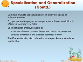
SlideShare a Scribd company logo
Chapter 2: Entity-Relationship
Model
Entity Sets
Relationship Sets
Design Issues
Mapping Constraints
Keys
E-R Diagram
Extended E-R Features
Design of an E-R Database Schema
Reduction of an E-R Schema to Tables

Database System Concepts

2.1

©Silberschatz, Korth and Sudarshan
Entity Sets
A database can be modeled as:
a collection of entities,
relationship among entities.

An entity is an object that exists and is distinguishable from other
objects.
Example: specific person, company, event, plant
Entities have attributes
Example: people have names and addresses

An entity set is a set of entities of the same type that share the
same properties.
Example: set of all persons, companies, trees, holidays

Database System Concepts

2.2

©Silberschatz, Korth and Sudarshan
Entity Sets customer and loan
customer-id customer- customer- customername street
city

Database System Concepts

2.3

loan- amount
number

©Silberschatz, Korth and Sudarshan
Attributes
An entity is represented by a set of attributes, that is descriptive
properties possessed by all members of an entity set.
Example:
customer = (customer-id, customer-name,
customer-street, customer-city)
loan = (loan-number, amount)
Domain – the set of permitted values for each attribute
Attribute types:
Simple and composite attributes.
Single-valued and multi-valued attributes
E.g. multivalued attribute: phone-numbers
Derived attributes
Can be computed from other attributes
E.g. age, given date of birth

Database System Concepts

2.4

©Silberschatz, Korth and Sudarshan
Composite Attributes

Database System Concepts

2.5

©Silberschatz, Korth and Sudarshan
Relationship Sets
A relationship is an association among several entities
Example:
Hayes
customer entity

depositor
relationship set

A-102
account entity

A relationship set is a mathematical relation among n ≥ 2 entities,
each taken from entity sets
{(e1, e2, … en) | e1 ∈ E1, e2 ∈ E2, …, en ∈ En}
where (e1, e2, …, en) is a relationship
Example:
(Hayes, A-102) ∈ depositor

Database System Concepts

2.6

©Silberschatz, Korth and Sudarshan
Relationship Set borrower

Database System Concepts

2.7

©Silberschatz, Korth and Sudarshan
Relationship Sets (Cont.)
An attribute can also be property of a relationship set.
For instance, the depositor relationship set between entity sets
customer and account may have the attribute access-date

Database System Concepts

2.8

©Silberschatz, Korth and Sudarshan
Degree of a Relationship Set
Refers to number of entity sets that participate in a relationship
set.
Relationship sets that involve two entity sets are binary (or degree
two). Generally, most relationship sets in a database system are
binary.
Relationship sets may involve more than two entity sets.
E.g. Suppose employees of a bank may have jobs
(responsibilities) at multiple branches, with different jobs at
different branches. Then there is a ternary relationship set
between entity sets employee, job and branch

Relationships between more than two entity sets are rare. Most
relationships are binary. (More on this later.)

Database System Concepts

2.9

©Silberschatz, Korth and Sudarshan
Mapping Cardinalities
Express the number of entities to which another entity can be
associated via a relationship set.
Most useful in describing binary relationship sets.
For a binary relationship set the mapping cardinality must be
one of the following types:
One to one
One to many
Many to one
Many to many

Database System Concepts

2.10

©Silberschatz, Korth and Sudarshan
Mapping Cardinalities

One to one

One to many

Note: Some elements in A and B may not be mapped to any
elements in the other set
Database System Concepts

2.11

©Silberschatz, Korth and Sudarshan
Mapping Cardinalities

Many to one

Many to many

Note: Some elements in A and B may not be mapped to any
elements in the other set
Database System Concepts

2.12

©Silberschatz, Korth and Sudarshan
Mapping Cardinalities affect ER Design
Can make access-date an attribute of account, instead of a
relationship attribute, if each account can have only one customer
I.e., the relationship from account to customer is many to one,
or equivalently, customer to account is one to many

Database System Concepts

2.13

©Silberschatz, Korth and Sudarshan
E-R Diagrams

Rectangles represent entity sets.
Diamonds represent relationship sets.
Lines link attributes to entity sets and entity sets to relationship sets.
Ellipses represent attributes
Double ellipses represent multivalued attributes.
Dashed ellipses denote derived attributes.
Underline indicates primary key attributes (will study later)
Database System Concepts

2.14

©Silberschatz, Korth and Sudarshan
E-R Diagram With Composite, Multivalued, and
Derived Attributes

Database System Concepts

2.15

©Silberschatz, Korth and Sudarshan
Relationship Sets with Attributes

Database System Concepts

2.16

©Silberschatz, Korth and Sudarshan
Roles
Entity sets of a relationship need not be distinct
The labels “manager” and “worker” are called roles; they specify how
employee entities interact via the works-for relationship set.
Roles are indicated in E-R diagrams by labeling the lines that connect
diamonds to rectangles.
Role labels are optional, and are used to clarify semantics of the
relationship

Database System Concepts

2.17

©Silberschatz, Korth and Sudarshan
Cardinality Constraints
We express cardinality constraints by drawing either a directed
line (→), signifying “one,” or an undirected line (—), signifying
“many,” between the relationship set and the entity set.
E.g.: One-to-one relationship:
A customer is associated with at most one loan via the relationship
borrower
A loan is associated with at most one customer via borrower

Database System Concepts

2.18

©Silberschatz, Korth and Sudarshan
One-To-Many Relationship
In the one-to-many relationship a loan is associated with at most
one customer via borrower, a customer is associated with
several (including 0) loans via borrower

Database System Concepts

2.19

©Silberschatz, Korth and Sudarshan
Many-To-One Relationships
In a many-to-one relationship a loan is associated with several
(including 0) customers via borrower, a customer is associated
with at most one loan via borrower

Database System Concepts

2.20

©Silberschatz, Korth and Sudarshan
Many-To-Many Relationship

A customer is associated with several (possibly 0) loans
via borrower
A loan is associated with several (possibly 0) customers
via borrower

Database System Concepts

2.21

©Silberschatz, Korth and Sudarshan
Participation of an Entity Set in a
Relationship Set
Total participation (indicated by double line): every entity in the entity
set participates in at least one relationship in the relationship set
E.g. participation of loan in borrower is total
every loan must have a customer associated to it via borrower
Partial participation: some entities may not participate in any
relationship in the relationship set
E.g. participation of customer in borrower is partial

Database System Concepts

2.22

©Silberschatz, Korth and Sudarshan
Alternative Notation for Cardinality
Limits
Cardinality limits can also express participation constraints

Database System Concepts

2.23

©Silberschatz, Korth and Sudarshan
Keys
A super key of an entity set is a set of one or more attributes
whose values uniquely determine each entity.
A candidate key of an entity set is a minimal super key
Customer-id is candidate key of customer
account-number is candidate key of account

Although several candidate keys may exist, one of the
candidate keys is selected to be the primary key.

Database System Concepts

2.24

©Silberschatz, Korth and Sudarshan
Keys for Relationship Sets
The combination of primary keys of the participating entity sets
forms a super key of a relationship set.
(customer-id, account-number) is the super key of depositor
NOTE: this means a pair of entity sets can have at most one
relationship in a particular relationship set.
E.g. if we wish to track all access-dates to each account by each
customer, we cannot assume a relationship for each access. We
can use a multivalued attribute though

Must consider the mapping cardinality of the relationship set
when deciding the what are the candidate keys
Need to consider semantics of relationship set in selecting the
primary key in case of more than one candidate key

Database System Concepts

2.25

©Silberschatz, Korth and Sudarshan
E-R Diagram with a Ternary
Relationship

Database System Concepts

2.26

©Silberschatz, Korth and Sudarshan
Cardinality Constraints on Ternary
Relationship
We allow at most one arrow out of a ternary (or greater degree)
relationship to indicate a cardinality constraint
E.g. an arrow from works-on to job indicates each employee works
on at most one job at any branch.
If there is more than one arrow, there are two ways of defining the
meaning.
E.g a ternary relationship R between A, B and C with arrows to B and C
could mean
1. each A entity is associated with a unique entity from B and C or
2. each pair of entities from (A, B) is associated with a unique C entity,
and each pair (A, C) is associated with a unique B
Each alternative has been used in different formalisms
To avoid confusion we outlaw more than one arrow

Database System Concepts

2.27

©Silberschatz, Korth and Sudarshan
Binary Vs. Non-Binary Relationships
Some relationships that appear to be non-binary may be better
represented using binary relationships
E.g. A ternary relationship parents, relating a child to his/her father and
mother, is best replaced by two binary relationships, father and mother
Using two binary relationships allows partial information (e.g. only
mother being know)
But there are some relationships that are naturally non-binary
E.g. works-on

Database System Concepts

2.28

©Silberschatz, Korth and Sudarshan
Converting Non-Binary Relationships to
Binary Form
In general, any non-binary relationship can be represented using binary
relationships by creating an artificial entity set.
Replace R between entity sets A, B and C by an entity set E, and three
relationship sets:

1. RA, relating E and A

2.RB, relating E and B

3. RC, relating E and C
Create a special identifying attribute for E
Add any attributes of R to E
For each relationship (ai , bi , ci) in R, create

1. a new entity ei in the entity set E

2. add (ei , ai ) to RA

3. add (ei , bi ) to RB

4. add (ei , ci ) to RC

Database System Concepts

2.29

©Silberschatz, Korth and Sudarshan
Converting Non-Binary Relationships
(Cont.)
Also need to translate constraints
Translating all constraints may not be possible
There may be instances in the translated schema that
cannot correspond to any instance of R
Exercise: add constraints to the relationships RA, RB and RC to
ensure that a newly created entity corresponds to exactly one entity
in each of entity sets A, B and C
We can avoid creating an identifying attribute by making E a weak
entity set (described shortly) identified by the three relationship sets

Database System Concepts

2.30

©Silberschatz, Korth and Sudarshan
Design Issues
Use of entity sets vs. attributes
Choice mainly depends on the structure of the enterprise being
modeled, and on the semantics associated with the attribute in
question.
Use of entity sets vs. relationship sets
Possible guideline is to designate a relationship set to describe an
action that occurs between entities
Binary versus n-ary relationship sets
Although it is possible to replace any nonbinary (n-ary, for n > 2)
relationship set by a number of distinct binary relationship sets, a nary relationship set shows more clearly that several entities
participate in a single relationship.
Placement of relationship attributes

Database System Concepts

2.31

©Silberschatz, Korth and Sudarshan
How about doing an ER design
interactively on the board?
Suggest an application to be
modeled.
Weak Entity Sets
An entity set that does not have a primary key is referred to as a
weak entity set.
The existence of a weak entity set depends on the existence of a
identifying entity set
it must relate to the identifying entity set via a total, one-to-many
relationship set from the identifying to the weak entity set
Identifying relationship depicted using a double diamond

The discriminator (or partial key) of a weak entity set is the set of
attributes that distinguishes among all the entities of a weak
entity set.
The primary key of a weak entity set is formed by the primary key
of the strong entity set on which the weak entity set is existence
dependent, plus the weak entity set’s discriminator.

Database System Concepts

2.33

©Silberschatz, Korth and Sudarshan
Weak Entity Sets (Cont.)
We depict a weak entity set by double rectangles.
We underline the discriminator of a weak entity set with a
dashed line.
payment-number – discriminator of the payment entity set
Primary key for payment – (loan-number, payment-number)

Database System Concepts

2.34

©Silberschatz, Korth and Sudarshan
Weak Entity Sets (Cont.)
Note: the primary key of the strong entity set is not explicitly
stored with the weak entity set, since it is implicit in the
identifying relationship.
If loan-number were explicitly stored, payment could be made a
strong entity, but then the relationship between payment and
loan would be duplicated by an implicit relationship defined by
the attribute loan-number common to payment and loan

Database System Concepts

2.35

©Silberschatz, Korth and Sudarshan
More Weak Entity Set Examples
In a university, a course is a strong entity and a course-offering
can be modeled as a weak entity
The discriminator of course-offering would be semester (including
year) and section-number (if there is more than one section)
If we model course-offering as a strong entity we would model
course-number as an attribute.
Then the relationship with course would be implicit in the coursenumber attribute

Database System Concepts

2.36

©Silberschatz, Korth and Sudarshan
Specialization
Top-down design process; we designate subgroupings within an
entity set that are distinctive from other entities in the set.
These subgroupings become lower-level entity sets that have
attributes or participate in relationships that do not apply to the
higher-level entity set.
Depicted by a triangle component labeled ISA (E.g. customer “is
a” person).
Attribute inheritance – a lower-level entity set inherits all the
attributes and relationship participation of the higher-level entity
set to which it is linked.

Database System Concepts

2.37

©Silberschatz, Korth and Sudarshan
Specialization Example

Database System Concepts

2.38

©Silberschatz, Korth and Sudarshan
Generalization
A bottom-up design process – combine a number of entity sets
that share the same features into a higher-level entity set.
Specialization and generalization are simple inversions of each
other; they are represented in an E-R diagram in the same way.
The terms specialization and generalization are used
interchangeably.

Database System Concepts

2.39

©Silberschatz, Korth and Sudarshan
Specialization and Generalization
(Contd.)
Can have multiple specializations of an entity set based on
different features.
E.g. permanent-employee vs. temporary-employee, in addition to
officer vs. secretary vs. teller
Each particular employee would be
a member of one of permanent-employee or temporary-employee,
and also a member of one of officer, secretary, or teller

The ISA relationship also referred to as superclass - subclass
relationship

Database System Concepts

2.40

©Silberschatz, Korth and Sudarshan
Design Constraints on a
Specialization/Generalization
Constraint on which entities can be members of a given
lower-level entity set.
condition-defined
E.g. all customers over 65 years are members of seniorcitizen entity set; senior-citizen ISA person.
user-defined

Constraint on whether or not entities may belong to more than
one lower-level entity set within a single generalization.
Disjoint
an entity can belong to only one lower-level entity set
Noted in E-R diagram by writing disjoint next to the ISA
triangle
Overlapping
an entity can belong to more than one lower-level entity set

Database System Concepts

2.41

©Silberschatz, Korth and Sudarshan
Design Constraints on a
Specialization/Generalization
(Contd.)
Completeness constraint -- specifies whether or not an entity in
the higher-level entity set must belong to at least one of the
lower-level entity sets within a generalization.
total : an entity must belong to one of the lower-level entity sets
partial: an entity need not belong to one of the lower-level entity
sets

Database System Concepts

2.42

©Silberschatz, Korth and Sudarshan
Aggregation
Consider the ternary relationship works-on, which we saw earlier
Suppose we want to record managers for tasks performed by an
employee at a branch

Database System Concepts

2.43

©Silberschatz, Korth and Sudarshan
Aggregation (Cont.)
Relationship sets works-on and manages represent overlapping
information
Every manages relationship corresponds to a works-on relationship
However, some works-on relationships may not correspond to any
manages relationships
So we can’t discard the works-on relationship

Eliminate this redundancy via aggregation
Treat relationship as an abstract entity
Allows relationships between relationships
Abstraction of relationship into new entity

Without introducing redundancy, the following diagram represents:
An employee works on a particular job at a particular branch
An employee, branch, job combination may have an associated manager

Database System Concepts

2.44

©Silberschatz, Korth and Sudarshan
E-R Diagram With Aggregation

Database System Concepts

2.45

©Silberschatz, Korth and Sudarshan
E-R Design Decisions
The use of an attribute or entity set to represent an object.
Whether a real-world concept is best expressed by an entity set
or a relationship set.
The use of a ternary relationship versus a pair of binary
relationships.
The use of a strong or weak entity set.
The use of specialization/generalization – contributes to
modularity in the design.
The use of aggregation – can treat the aggregate entity set as a
single unit without concern for the details of its internal structure.

Database System Concepts

2.46

©Silberschatz, Korth and Sudarshan
E-R Diagram for a Banking
Enterprise

Database System Concepts

2.47

©Silberschatz, Korth and Sudarshan
How about doing another ER
design interactively on the board?
Summary of Symbols Used in E-R
Notation

Database System Concepts

2.49

©Silberschatz, Korth and Sudarshan
Summary of Symbols (Cont.)

Database System Concepts

2.50

©Silberschatz, Korth and Sudarshan
Alternative E-R Notations

Database System Concepts

2.51

©Silberschatz, Korth and Sudarshan
UML
UML: Unified Modeling Language
UML has many components to graphically model different
aspects of an entire software system
UML Class Diagrams correspond to E-R Diagram, but several
differences.

Database System Concepts

2.52

©Silberschatz, Korth and Sudarshan
Summary of UML Class Diagram Notation

Database System Concepts

2.53

©Silberschatz, Korth and Sudarshan
UML Class Diagrams (Contd.)
Entity sets are shown as boxes, and attributes are shown within the
box, rather than as separate ellipses in E-R diagrams.
Binary relationship sets are represented in UML by just drawing a
line connecting the entity sets. The relationship set name is written
adjacent to the line.
The role played by an entity set in a relationship set may also be
specified by writing the role name on the line, adjacent to the entity
set.
The relationship set name may alternatively be written in a box,
along with attributes of the relationship set, and the box is
connected, using a dotted line, to the line depicting the relationship
set.
Non-binary relationships drawn using diamonds, just as in ER
diagrams

Database System Concepts

2.54

©Silberschatz, Korth and Sudarshan
UML Class Diagram Notation (Cont.)

overlapping

disjoint

*Note reversal of position in cardinality constraint depiction
*Generalization can use merged or separate arrows independent
of disjoint/overlapping
Database System Concepts

2.55

©Silberschatz, Korth and Sudarshan
UML Class Diagrams (Contd.)
Cardinality constraints are specified in the form l..h, where l denotes
the minimum and h the maximum number of relationships an entity
can participate in.
Beware: the positioning of the constraints is exactly the reverse of the
positioning of constraints in E-R diagrams.
The constraint 0..* on the E2 side and 0..1 on the E1 side means that
each E2 entity can participate in at most one relationship, whereas
each E1 entity can participate in many relationships; in other words,
the relationship is many to one from E2 to E1.
Single values, such as 1 or * may be written on edges; The single
value 1 on an edge is treated as equivalent to 1..1, while * is
equivalent to 0..*.

Database System Concepts

2.56

©Silberschatz, Korth and Sudarshan
Reduction of an E-R Schema to
Tables
Primary keys allow entity sets and relationship sets to be
expressed uniformly as tables which represent the
contents of the database.
A database which conforms to an E-R diagram can be
represented by a collection of tables.
For each entity set and relationship set there is a unique
table which is assigned the name of the corresponding
entity set or relationship set.
Each table has a number of columns (generally
corresponding to attributes), which have unique names.
Converting an E-R diagram to a table format is the basis
for deriving a relational database design from an E-R
diagram.

Database System Concepts

2.57

©Silberschatz, Korth and Sudarshan
Representing Entity Sets as Tables
A strong entity set reduces to a table with the same attributes.

Database System Concepts

2.58

©Silberschatz, Korth and Sudarshan
Composite and Multivalued
Attributes
Composite attributes are flattened out by creating a separate attribute
for each component attribute
E.g. given entity set customer with composite attribute name with
component attributes first-name and last-name the table corresponding
to the entity set has two attributes
name.first-name and name.last-name

A multivalued attribute M of an entity E is represented by a separate
table EM
Table EM has attributes corresponding to the primary key of E and an
attribute corresponding to multivalued attribute M
E.g. Multivalued attribute dependent-names of employee is represented
by a table
employee-dependent-names( employee-id, dname)
Each value of the multivalued attribute maps to a separate row of the
table EM
E.g., an employee entity with primary key John and
dependents Johnson and Johndotir maps to two rows:
(John, Johnson) and (John, Johndotir)
Database System Concepts

2.59

©Silberschatz, Korth and Sudarshan
Representing Weak Entity Sets
A weak entity set becomes a table that includes a column for
the primary key of the identifying strong entity set

Database System Concepts

2.60

©Silberschatz, Korth and Sudarshan
Representing Relationship Sets
as Tables
A many-to-many relationship set is represented as a table with
columns for the primary keys of the two participating entity sets,
and any descriptive attributes of the relationship set.
E.g.: table for relationship set borrower

Database System Concepts

2.61

©Silberschatz, Korth and Sudarshan
Redundancy of Tables
Many-to-one and one-to-many relationship sets that are total
on the many-side can be represented by adding an extra
attribute to the many side, containing the primary key of the
one side
E.g.: Instead of creating a table for relationship accountbranch, add an attribute branch to the entity set account

Database System Concepts

2.62

©Silberschatz, Korth and Sudarshan
Redundancy of Tables (Cont.)
For one-to-one relationship sets, either side can be chosen to act
as the “many” side
That is, extra attribute can be added to either of the tables
corresponding to the two entity sets

If participation is partial on the many side, replacing a table by an
extra attribute in the relation corresponding to the “many” side
could result in null values
The table corresponding to a relationship set linking a weak
entity set to its identifying strong entity set is redundant.
E.g. The payment table already contains the information that would
appear in the loan-payment table (i.e., the columns loan-number and
payment-number).

Database System Concepts

2.63

©Silberschatz, Korth and Sudarshan
Representing Specialization as
Tables
Method 1:
Form a table for the higher level entity
Form a table for each lower level entity set, include primary key of
higher level entity set and local attributes
table
person
customer
employee

table attributes
name, street, city
name, credit-rating
name, salary

Drawback: getting information about, e.g., employee requires
accessing two tables

Database System Concepts

2.64

©Silberschatz, Korth and Sudarshan
Representing Specialization as
Tables (Cont.)
Method 2:
Form a table for each entity set with all local and inherited
attributes
table
table attributes
person
name, street, city
customer
name, street, city, credit-rating
employee
name, street, city, salary
If specialization is total, table for generalized entity (person) not
required to store information
Can be defined as a “view” relation containing union of
specialization tables
But explicit table may still be needed for foreign key constraints
Drawback: street and city may be stored redundantly for persons
who are both customers and employees

Database System Concepts

2.65

©Silberschatz, Korth and Sudarshan
Relations Corresponding to
Aggregation
To represent aggregation, create a table containing
primary key of the aggregated relationship,
the primary key of the associated entity set
Any descriptive attributes

Database System Concepts

2.66

©Silberschatz, Korth and Sudarshan
Relations Corresponding to
Aggregation (Cont.)
E.g. to represent aggregation manages between relationship
works-on and entity set manager, create a table
manages(employee-id, branch-name, title, manager-name)
Table works-on is redundant provided we are willing to store
null values for attribute manager-name in table manages

Database System Concepts

2.67

©Silberschatz, Korth and Sudarshan
End of Chapter 2
E-R Diagram for Exercise 2.10

Database System Concepts

2.69

©Silberschatz, Korth and Sudarshan
E-R Diagram for Exercise 2.15

Database System Concepts

2.70

©Silberschatz, Korth and Sudarshan
E-R Diagram for Exercise 2.22

Database System Concepts

2.71

©Silberschatz, Korth and Sudarshan
E-R Diagram for Exercise 2.15

Database System Concepts

2.72

©Silberschatz, Korth and Sudarshan
Existence Dependencies
If the existence of entity x depends on the existence of
entity y, then x is said to be existence dependent on y.
y is a dominant entity (in example below, loan)
x is a subordinate entity (in example below, payment)

loan

loan-payment

payment

If a loan entity is deleted, then all its associated payment entities
must be deleted also.

Database System Concepts

2.73

©Silberschatz, Korth and Sudarshan

More Related Content

What's hot

5. Other Relational Languages in DBMS
5. Other Relational Languages in DBMS5. Other Relational Languages in DBMS
5. Other Relational Languages in DBMSkoolkampus
 
Dbms ii mca-ch3-er-model-2013
Dbms ii mca-ch3-er-model-2013Dbms ii mca-ch3-er-model-2013
Dbms ii mca-ch3-er-model-2013
Prosanta Ghosh
 
The three level of data modeling
The three level of data modelingThe three level of data modeling
The three level of data modelingsharmila_yusof
 
Chapter 6 relational data model and relational
Chapter  6  relational data model and relationalChapter  6  relational data model and relational
Chapter 6 relational data model and relationalJafar Nesargi
 
Chapter3 the relational data model and the relation database constraints part2
Chapter3 the relational data model and the relation database constraints part2Chapter3 the relational data model and the relation database constraints part2
Chapter3 the relational data model and the relation database constraints part2
eidah20
 
Fundamentals of database system - Relational data model and relational datab...
Fundamentals of database system  - Relational data model and relational datab...Fundamentals of database system  - Relational data model and relational datab...
Fundamentals of database system - Relational data model and relational datab...
Mustafa Kamel Mohammadi
 
RDBMS_Unit 01
RDBMS_Unit 01RDBMS_Unit 01
RDBMS_Unit 01
Prashanth Shivakumar
 
dbms first unit
dbms first unitdbms first unit
dbms first unit
Raghu Bright
 
Informatica Data Modelling : Importance of Conceptual Models
Informatica Data Modelling : Importance of  Conceptual ModelsInformatica Data Modelling : Importance of  Conceptual Models
Informatica Data Modelling : Importance of Conceptual Models
ZaranTech LLC
 
Dbms ER Model
Dbms ER ModelDbms ER Model
Dbms ER Model
Sreedhar Chowdam
 
The relational data model part[1]
The relational data model part[1]The relational data model part[1]
The relational data model part[1]
Bashir Rezaie
 
Chapter 7 relation database language
Chapter 7 relation database languageChapter 7 relation database language
Chapter 7 relation database languageJafar Nesargi
 
Bca examination 2017 dbms
Bca examination 2017 dbmsBca examination 2017 dbms
Bca examination 2017 dbms
Anjaan Gajendra
 
Relational database intro for marketers
Relational database intro for marketersRelational database intro for marketers
Relational database intro for marketers
Steve Finlay
 
3. Relational Models in DBMS
3. Relational Models in DBMS3. Relational Models in DBMS
3. Relational Models in DBMSkoolkampus
 
Database : Relational Data Model
Database : Relational Data ModelDatabase : Relational Data Model
Database : Relational Data Model
Smriti Jain
 

What's hot (20)

5. Other Relational Languages in DBMS
5. Other Relational Languages in DBMS5. Other Relational Languages in DBMS
5. Other Relational Languages in DBMS
 
Dbms ii mca-ch3-er-model-2013
Dbms ii mca-ch3-er-model-2013Dbms ii mca-ch3-er-model-2013
Dbms ii mca-ch3-er-model-2013
 
Database Modeling
Database ModelingDatabase Modeling
Database Modeling
 
The three level of data modeling
The three level of data modelingThe three level of data modeling
The three level of data modeling
 
Chapter 6 relational data model and relational
Chapter  6  relational data model and relationalChapter  6  relational data model and relational
Chapter 6 relational data model and relational
 
ch14
ch14ch14
ch14
 
Chapter3 the relational data model and the relation database constraints part2
Chapter3 the relational data model and the relation database constraints part2Chapter3 the relational data model and the relation database constraints part2
Chapter3 the relational data model and the relation database constraints part2
 
Fundamentals of database system - Relational data model and relational datab...
Fundamentals of database system  - Relational data model and relational datab...Fundamentals of database system  - Relational data model and relational datab...
Fundamentals of database system - Relational data model and relational datab...
 
RDBMS_Unit 01
RDBMS_Unit 01RDBMS_Unit 01
RDBMS_Unit 01
 
ch6
ch6ch6
ch6
 
dbms first unit
dbms first unitdbms first unit
dbms first unit
 
Informatica Data Modelling : Importance of Conceptual Models
Informatica Data Modelling : Importance of  Conceptual ModelsInformatica Data Modelling : Importance of  Conceptual Models
Informatica Data Modelling : Importance of Conceptual Models
 
Dbms ER Model
Dbms ER ModelDbms ER Model
Dbms ER Model
 
The relational data model part[1]
The relational data model part[1]The relational data model part[1]
The relational data model part[1]
 
Chapter 7 relation database language
Chapter 7 relation database languageChapter 7 relation database language
Chapter 7 relation database language
 
Bca examination 2017 dbms
Bca examination 2017 dbmsBca examination 2017 dbms
Bca examination 2017 dbms
 
Relational database intro for marketers
Relational database intro for marketersRelational database intro for marketers
Relational database intro for marketers
 
parth presentation
parth presentationparth presentation
parth presentation
 
3. Relational Models in DBMS
3. Relational Models in DBMS3. Relational Models in DBMS
3. Relational Models in DBMS
 
Database : Relational Data Model
Database : Relational Data ModelDatabase : Relational Data Model
Database : Relational Data Model
 

Viewers also liked

App c
App cApp c
Hci [6]interaction design
Hci [6]interaction designHci [6]interaction design
Hci [6]interaction design
Welly Dian Astika
 
Sebaran peluang-bersama
Sebaran peluang-bersamaSebaran peluang-bersama
Sebaran peluang-bersama
Welly Dian Astika
 
E3 chap-04
E3 chap-04E3 chap-04
E3 chap-04
Welly Dian Astika
 
E3 chap-03
E3 chap-03E3 chap-03
E3 chap-03
Welly Dian Astika
 
E3 chap-11
E3 chap-11E3 chap-11
E3 chap-11
Welly Dian Astika
 
Ch8 main memory
Ch8   main memoryCh8   main memory
Ch8 main memory
Welly Dian Astika
 
Peubah acak-kontinu
Peubah acak-kontinuPeubah acak-kontinu
Peubah acak-kontinu
Welly Dian Astika
 
Ch11 file system implementation
Ch11   file system implementationCh11   file system implementation
Ch11 file system implementation
Welly Dian Astika
 
Ch15
Ch15Ch15
E3 chap-20
E3 chap-20E3 chap-20
E3 chap-20
Welly Dian Astika
 
Imk pertemuan-1
Imk pertemuan-1Imk pertemuan-1
Imk pertemuan-1
Welly Dian Astika
 
Ch22
Ch22Ch22
E3 chap-06
E3 chap-06E3 chap-06
E3 chap-06
Welly Dian Astika
 
Ch13 protection
Ch13   protectionCh13   protection
Ch13 protection
Welly Dian Astika
 
Ch6 cpu scheduling
Ch6   cpu schedulingCh6   cpu scheduling
Ch6 cpu scheduling
Welly Dian Astika
 
Ch12
Ch12Ch12
Ch17
Ch17Ch17
Ch1
Ch1Ch1

Viewers also liked (19)

App c
App cApp c
App c
 
Hci [6]interaction design
Hci [6]interaction designHci [6]interaction design
Hci [6]interaction design
 
Sebaran peluang-bersama
Sebaran peluang-bersamaSebaran peluang-bersama
Sebaran peluang-bersama
 
E3 chap-04
E3 chap-04E3 chap-04
E3 chap-04
 
E3 chap-03
E3 chap-03E3 chap-03
E3 chap-03
 
E3 chap-11
E3 chap-11E3 chap-11
E3 chap-11
 
Ch8 main memory
Ch8   main memoryCh8   main memory
Ch8 main memory
 
Peubah acak-kontinu
Peubah acak-kontinuPeubah acak-kontinu
Peubah acak-kontinu
 
Ch11 file system implementation
Ch11   file system implementationCh11   file system implementation
Ch11 file system implementation
 
Ch15
Ch15Ch15
Ch15
 
E3 chap-20
E3 chap-20E3 chap-20
E3 chap-20
 
Imk pertemuan-1
Imk pertemuan-1Imk pertemuan-1
Imk pertemuan-1
 
Ch22
Ch22Ch22
Ch22
 
E3 chap-06
E3 chap-06E3 chap-06
E3 chap-06
 
Ch13 protection
Ch13   protectionCh13   protection
Ch13 protection
 
Ch6 cpu scheduling
Ch6   cpu schedulingCh6   cpu scheduling
Ch6 cpu scheduling
 
Ch12
Ch12Ch12
Ch12
 
Ch17
Ch17Ch17
Ch17
 
Ch1
Ch1Ch1
Ch1
 

Similar to Ch2

E-r Model.ppt
E-r Model.pptE-r Model.ppt
E-r Model.ppt
ManoRanjani30
 
DBA
DBADBA
DataBase ch2
DataBase ch2DataBase ch2
DataBase ch2
ayman_alawin
 
ER Model and other topics in DBMS
ER Model and other topics in DBMSER Model and other topics in DBMS
ER Model and other topics in DBMS
HarinarayananR2
 
U2_ER_modeling.pptx
U2_ER_modeling.pptxU2_ER_modeling.pptx
U2_ER_modeling.pptx
ssusera7b660
 
Unit 3 final.pptx
Unit 3 final.pptxUnit 3 final.pptx
Unit 3 final.pptx
MaximusAranha
 
Data & Databases
Data & Databases Data & Databases
Data & Databases
Tharindu Weerasinghe
 
Chapter 2. Concepctual design -.pptx
Chapter 2. Concepctual design -.pptxChapter 2. Concepctual design -.pptx
Chapter 2. Concepctual design -.pptx
santosh96234
 
Er model
Er modelEr model
Er model
slidenageswaran
 
Test presentation
Test presentationTest presentation
Test presentation
nuvole
 
2. Entity Relationship Model in DBMS
2. Entity Relationship Model in DBMS2. Entity Relationship Model in DBMS
2. Entity Relationship Model in DBMSkoolkampus
 
E R Model details.ppt
E R Model details.pptE R Model details.ppt
E R Model details.ppt
ShivareddyGangam
 
ER model
ER modelER model
ER model
paddu123
 
Er model
Er modelEr model
Er model
paddu123
 
ER Model Ppt.ppt
ER Model Ppt.pptER Model Ppt.ppt
ER Model Ppt.ppt
DivyaRasrogi
 
ER Models.ppt
ER Models.pptER Models.ppt
ER Models.ppt
PrathamSinghal13
 
DATABASE MANAGEMENT SYSTEMS ER MODEL.ppt
DATABASE MANAGEMENT SYSTEMS ER MODEL.pptDATABASE MANAGEMENT SYSTEMS ER MODEL.ppt
DATABASE MANAGEMENT SYSTEMS ER MODEL.ppt
YashShirude1
 

Similar to Ch2 (20)

ch2.ppt
ch2.pptch2.ppt
ch2.ppt
 
ER.ppt
ER.pptER.ppt
ER.ppt
 
E-r Model.ppt
E-r Model.pptE-r Model.ppt
E-r Model.ppt
 
DBA
DBADBA
DBA
 
DataBase ch2
DataBase ch2DataBase ch2
DataBase ch2
 
ER Model and other topics in DBMS
ER Model and other topics in DBMSER Model and other topics in DBMS
ER Model and other topics in DBMS
 
U2_ER_modeling.pptx
U2_ER_modeling.pptxU2_ER_modeling.pptx
U2_ER_modeling.pptx
 
Unit 3 final.pptx
Unit 3 final.pptxUnit 3 final.pptx
Unit 3 final.pptx
 
Data & Databases
Data & Databases Data & Databases
Data & Databases
 
Chapter 2. Concepctual design -.pptx
Chapter 2. Concepctual design -.pptxChapter 2. Concepctual design -.pptx
Chapter 2. Concepctual design -.pptx
 
Er model
Er modelEr model
Er model
 
Test presentation
Test presentationTest presentation
Test presentation
 
2. Entity Relationship Model in DBMS
2. Entity Relationship Model in DBMS2. Entity Relationship Model in DBMS
2. Entity Relationship Model in DBMS
 
E R Model details.ppt
E R Model details.pptE R Model details.ppt
E R Model details.ppt
 
dbms
dbmsdbms
dbms
 
ER model
ER modelER model
ER model
 
Er model
Er modelEr model
Er model
 
ER Model Ppt.ppt
ER Model Ppt.pptER Model Ppt.ppt
ER Model Ppt.ppt
 
ER Models.ppt
ER Models.pptER Models.ppt
ER Models.ppt
 
DATABASE MANAGEMENT SYSTEMS ER MODEL.ppt
DATABASE MANAGEMENT SYSTEMS ER MODEL.pptDATABASE MANAGEMENT SYSTEMS ER MODEL.ppt
DATABASE MANAGEMENT SYSTEMS ER MODEL.ppt
 

Recently uploaded

How libraries can support authors with open access requirements for UKRI fund...
How libraries can support authors with open access requirements for UKRI fund...How libraries can support authors with open access requirements for UKRI fund...
How libraries can support authors with open access requirements for UKRI fund...
Jisc
 
1.4 modern child centered education - mahatma gandhi-2.pptx
1.4 modern child centered education - mahatma gandhi-2.pptx1.4 modern child centered education - mahatma gandhi-2.pptx
1.4 modern child centered education - mahatma gandhi-2.pptx
JosvitaDsouza2
 
Unit 2- Research Aptitude (UGC NET Paper I).pdf
Unit 2- Research Aptitude (UGC NET Paper I).pdfUnit 2- Research Aptitude (UGC NET Paper I).pdf
Unit 2- Research Aptitude (UGC NET Paper I).pdf
Thiyagu K
 
Operation Blue Star - Saka Neela Tara
Operation Blue Star   -  Saka Neela TaraOperation Blue Star   -  Saka Neela Tara
Operation Blue Star - Saka Neela Tara
Balvir Singh
 
The approach at University of Liverpool.pptx
The approach at University of Liverpool.pptxThe approach at University of Liverpool.pptx
The approach at University of Liverpool.pptx
Jisc
 
The geography of Taylor Swift - some ideas
The geography of Taylor Swift - some ideasThe geography of Taylor Swift - some ideas
The geography of Taylor Swift - some ideas
GeoBlogs
 
Template Jadual Bertugas Kelas (Boleh Edit)
Template Jadual Bertugas Kelas (Boleh Edit)Template Jadual Bertugas Kelas (Boleh Edit)
Template Jadual Bertugas Kelas (Boleh Edit)
rosedainty
 
Thesis Statement for students diagnonsed withADHD.ppt
Thesis Statement for students diagnonsed withADHD.pptThesis Statement for students diagnonsed withADHD.ppt
Thesis Statement for students diagnonsed withADHD.ppt
EverAndrsGuerraGuerr
 
Sectors of the Indian Economy - Class 10 Study Notes pdf
Sectors of the Indian Economy - Class 10 Study Notes pdfSectors of the Indian Economy - Class 10 Study Notes pdf
Sectors of the Indian Economy - Class 10 Study Notes pdf
Vivekanand Anglo Vedic Academy
 
TESDA TM1 REVIEWER FOR NATIONAL ASSESSMENT WRITTEN AND ORAL QUESTIONS WITH A...
TESDA TM1 REVIEWER  FOR NATIONAL ASSESSMENT WRITTEN AND ORAL QUESTIONS WITH A...TESDA TM1 REVIEWER  FOR NATIONAL ASSESSMENT WRITTEN AND ORAL QUESTIONS WITH A...
TESDA TM1 REVIEWER FOR NATIONAL ASSESSMENT WRITTEN AND ORAL QUESTIONS WITH A...
EugeneSaldivar
 
Ethnobotany and Ethnopharmacology ......
Ethnobotany and Ethnopharmacology ......Ethnobotany and Ethnopharmacology ......
Ethnobotany and Ethnopharmacology ......
Ashokrao Mane college of Pharmacy Peth-Vadgaon
 
Cambridge International AS A Level Biology Coursebook - EBook (MaryFosbery J...
Cambridge International AS  A Level Biology Coursebook - EBook (MaryFosbery J...Cambridge International AS  A Level Biology Coursebook - EBook (MaryFosbery J...
Cambridge International AS A Level Biology Coursebook - EBook (MaryFosbery J...
AzmatAli747758
 
Digital Tools and AI for Teaching Learning and Research
Digital Tools and AI for Teaching Learning and ResearchDigital Tools and AI for Teaching Learning and Research
Digital Tools and AI for Teaching Learning and Research
Vikramjit Singh
 
Synthetic Fiber Construction in lab .pptx
Synthetic Fiber Construction in lab .pptxSynthetic Fiber Construction in lab .pptx
Synthetic Fiber Construction in lab .pptx
Pavel ( NSTU)
 
How to Break the cycle of negative Thoughts
How to Break the cycle of negative ThoughtsHow to Break the cycle of negative Thoughts
How to Break the cycle of negative Thoughts
Col Mukteshwar Prasad
 
Polish students' mobility in the Czech Republic
Polish students' mobility in the Czech RepublicPolish students' mobility in the Czech Republic
Polish students' mobility in the Czech Republic
Anna Sz.
 
The Art Pastor's Guide to Sabbath | Steve Thomason
The Art Pastor's Guide to Sabbath | Steve ThomasonThe Art Pastor's Guide to Sabbath | Steve Thomason
The Art Pastor's Guide to Sabbath | Steve Thomason
Steve Thomason
 
Instructions for Submissions thorugh G- Classroom.pptx
Instructions for Submissions thorugh G- Classroom.pptxInstructions for Submissions thorugh G- Classroom.pptx
Instructions for Submissions thorugh G- Classroom.pptx
Jheel Barad
 
Fish and Chips - have they had their chips
Fish and Chips - have they had their chipsFish and Chips - have they had their chips
Fish and Chips - have they had their chips
GeoBlogs
 
ESC Beyond Borders _From EU to You_ InfoPack general.pdf
ESC Beyond Borders _From EU to You_ InfoPack general.pdfESC Beyond Borders _From EU to You_ InfoPack general.pdf
ESC Beyond Borders _From EU to You_ InfoPack general.pdf
Fundacja Rozwoju Społeczeństwa Przedsiębiorczego
 

Recently uploaded (20)

How libraries can support authors with open access requirements for UKRI fund...
How libraries can support authors with open access requirements for UKRI fund...How libraries can support authors with open access requirements for UKRI fund...
How libraries can support authors with open access requirements for UKRI fund...
 
1.4 modern child centered education - mahatma gandhi-2.pptx
1.4 modern child centered education - mahatma gandhi-2.pptx1.4 modern child centered education - mahatma gandhi-2.pptx
1.4 modern child centered education - mahatma gandhi-2.pptx
 
Unit 2- Research Aptitude (UGC NET Paper I).pdf
Unit 2- Research Aptitude (UGC NET Paper I).pdfUnit 2- Research Aptitude (UGC NET Paper I).pdf
Unit 2- Research Aptitude (UGC NET Paper I).pdf
 
Operation Blue Star - Saka Neela Tara
Operation Blue Star   -  Saka Neela TaraOperation Blue Star   -  Saka Neela Tara
Operation Blue Star - Saka Neela Tara
 
The approach at University of Liverpool.pptx
The approach at University of Liverpool.pptxThe approach at University of Liverpool.pptx
The approach at University of Liverpool.pptx
 
The geography of Taylor Swift - some ideas
The geography of Taylor Swift - some ideasThe geography of Taylor Swift - some ideas
The geography of Taylor Swift - some ideas
 
Template Jadual Bertugas Kelas (Boleh Edit)
Template Jadual Bertugas Kelas (Boleh Edit)Template Jadual Bertugas Kelas (Boleh Edit)
Template Jadual Bertugas Kelas (Boleh Edit)
 
Thesis Statement for students diagnonsed withADHD.ppt
Thesis Statement for students diagnonsed withADHD.pptThesis Statement for students diagnonsed withADHD.ppt
Thesis Statement for students diagnonsed withADHD.ppt
 
Sectors of the Indian Economy - Class 10 Study Notes pdf
Sectors of the Indian Economy - Class 10 Study Notes pdfSectors of the Indian Economy - Class 10 Study Notes pdf
Sectors of the Indian Economy - Class 10 Study Notes pdf
 
TESDA TM1 REVIEWER FOR NATIONAL ASSESSMENT WRITTEN AND ORAL QUESTIONS WITH A...
TESDA TM1 REVIEWER  FOR NATIONAL ASSESSMENT WRITTEN AND ORAL QUESTIONS WITH A...TESDA TM1 REVIEWER  FOR NATIONAL ASSESSMENT WRITTEN AND ORAL QUESTIONS WITH A...
TESDA TM1 REVIEWER FOR NATIONAL ASSESSMENT WRITTEN AND ORAL QUESTIONS WITH A...
 
Ethnobotany and Ethnopharmacology ......
Ethnobotany and Ethnopharmacology ......Ethnobotany and Ethnopharmacology ......
Ethnobotany and Ethnopharmacology ......
 
Cambridge International AS A Level Biology Coursebook - EBook (MaryFosbery J...
Cambridge International AS  A Level Biology Coursebook - EBook (MaryFosbery J...Cambridge International AS  A Level Biology Coursebook - EBook (MaryFosbery J...
Cambridge International AS A Level Biology Coursebook - EBook (MaryFosbery J...
 
Digital Tools and AI for Teaching Learning and Research
Digital Tools and AI for Teaching Learning and ResearchDigital Tools and AI for Teaching Learning and Research
Digital Tools and AI for Teaching Learning and Research
 
Synthetic Fiber Construction in lab .pptx
Synthetic Fiber Construction in lab .pptxSynthetic Fiber Construction in lab .pptx
Synthetic Fiber Construction in lab .pptx
 
How to Break the cycle of negative Thoughts
How to Break the cycle of negative ThoughtsHow to Break the cycle of negative Thoughts
How to Break the cycle of negative Thoughts
 
Polish students' mobility in the Czech Republic
Polish students' mobility in the Czech RepublicPolish students' mobility in the Czech Republic
Polish students' mobility in the Czech Republic
 
The Art Pastor's Guide to Sabbath | Steve Thomason
The Art Pastor's Guide to Sabbath | Steve ThomasonThe Art Pastor's Guide to Sabbath | Steve Thomason
The Art Pastor's Guide to Sabbath | Steve Thomason
 
Instructions for Submissions thorugh G- Classroom.pptx
Instructions for Submissions thorugh G- Classroom.pptxInstructions for Submissions thorugh G- Classroom.pptx
Instructions for Submissions thorugh G- Classroom.pptx
 
Fish and Chips - have they had their chips
Fish and Chips - have they had their chipsFish and Chips - have they had their chips
Fish and Chips - have they had their chips
 
ESC Beyond Borders _From EU to You_ InfoPack general.pdf
ESC Beyond Borders _From EU to You_ InfoPack general.pdfESC Beyond Borders _From EU to You_ InfoPack general.pdf
ESC Beyond Borders _From EU to You_ InfoPack general.pdf
 

Ch2

  • 1. Chapter 2: Entity-Relationship Model Entity Sets Relationship Sets Design Issues Mapping Constraints Keys E-R Diagram Extended E-R Features Design of an E-R Database Schema Reduction of an E-R Schema to Tables Database System Concepts 2.1 ©Silberschatz, Korth and Sudarshan
  • 2. Entity Sets A database can be modeled as: a collection of entities, relationship among entities. An entity is an object that exists and is distinguishable from other objects. Example: specific person, company, event, plant Entities have attributes Example: people have names and addresses An entity set is a set of entities of the same type that share the same properties. Example: set of all persons, companies, trees, holidays Database System Concepts 2.2 ©Silberschatz, Korth and Sudarshan
  • 3. Entity Sets customer and loan customer-id customer- customer- customername street city Database System Concepts 2.3 loan- amount number ©Silberschatz, Korth and Sudarshan
  • 4. Attributes An entity is represented by a set of attributes, that is descriptive properties possessed by all members of an entity set. Example: customer = (customer-id, customer-name, customer-street, customer-city) loan = (loan-number, amount) Domain – the set of permitted values for each attribute Attribute types: Simple and composite attributes. Single-valued and multi-valued attributes E.g. multivalued attribute: phone-numbers Derived attributes Can be computed from other attributes E.g. age, given date of birth Database System Concepts 2.4 ©Silberschatz, Korth and Sudarshan
  • 5. Composite Attributes Database System Concepts 2.5 ©Silberschatz, Korth and Sudarshan
  • 6. Relationship Sets A relationship is an association among several entities Example: Hayes customer entity depositor relationship set A-102 account entity A relationship set is a mathematical relation among n ≥ 2 entities, each taken from entity sets {(e1, e2, … en) | e1 ∈ E1, e2 ∈ E2, …, en ∈ En} where (e1, e2, …, en) is a relationship Example: (Hayes, A-102) ∈ depositor Database System Concepts 2.6 ©Silberschatz, Korth and Sudarshan
  • 7. Relationship Set borrower Database System Concepts 2.7 ©Silberschatz, Korth and Sudarshan
  • 8. Relationship Sets (Cont.) An attribute can also be property of a relationship set. For instance, the depositor relationship set between entity sets customer and account may have the attribute access-date Database System Concepts 2.8 ©Silberschatz, Korth and Sudarshan
  • 9. Degree of a Relationship Set Refers to number of entity sets that participate in a relationship set. Relationship sets that involve two entity sets are binary (or degree two). Generally, most relationship sets in a database system are binary. Relationship sets may involve more than two entity sets. E.g. Suppose employees of a bank may have jobs (responsibilities) at multiple branches, with different jobs at different branches. Then there is a ternary relationship set between entity sets employee, job and branch Relationships between more than two entity sets are rare. Most relationships are binary. (More on this later.) Database System Concepts 2.9 ©Silberschatz, Korth and Sudarshan
  • 10. Mapping Cardinalities Express the number of entities to which another entity can be associated via a relationship set. Most useful in describing binary relationship sets. For a binary relationship set the mapping cardinality must be one of the following types: One to one One to many Many to one Many to many Database System Concepts 2.10 ©Silberschatz, Korth and Sudarshan
  • 11. Mapping Cardinalities One to one One to many Note: Some elements in A and B may not be mapped to any elements in the other set Database System Concepts 2.11 ©Silberschatz, Korth and Sudarshan
  • 12. Mapping Cardinalities Many to one Many to many Note: Some elements in A and B may not be mapped to any elements in the other set Database System Concepts 2.12 ©Silberschatz, Korth and Sudarshan
  • 13. Mapping Cardinalities affect ER Design Can make access-date an attribute of account, instead of a relationship attribute, if each account can have only one customer I.e., the relationship from account to customer is many to one, or equivalently, customer to account is one to many Database System Concepts 2.13 ©Silberschatz, Korth and Sudarshan
  • 14. E-R Diagrams Rectangles represent entity sets. Diamonds represent relationship sets. Lines link attributes to entity sets and entity sets to relationship sets. Ellipses represent attributes Double ellipses represent multivalued attributes. Dashed ellipses denote derived attributes. Underline indicates primary key attributes (will study later) Database System Concepts 2.14 ©Silberschatz, Korth and Sudarshan
  • 15. E-R Diagram With Composite, Multivalued, and Derived Attributes Database System Concepts 2.15 ©Silberschatz, Korth and Sudarshan
  • 16. Relationship Sets with Attributes Database System Concepts 2.16 ©Silberschatz, Korth and Sudarshan
  • 17. Roles Entity sets of a relationship need not be distinct The labels “manager” and “worker” are called roles; they specify how employee entities interact via the works-for relationship set. Roles are indicated in E-R diagrams by labeling the lines that connect diamonds to rectangles. Role labels are optional, and are used to clarify semantics of the relationship Database System Concepts 2.17 ©Silberschatz, Korth and Sudarshan
  • 18. Cardinality Constraints We express cardinality constraints by drawing either a directed line (→), signifying “one,” or an undirected line (—), signifying “many,” between the relationship set and the entity set. E.g.: One-to-one relationship: A customer is associated with at most one loan via the relationship borrower A loan is associated with at most one customer via borrower Database System Concepts 2.18 ©Silberschatz, Korth and Sudarshan
  • 19. One-To-Many Relationship In the one-to-many relationship a loan is associated with at most one customer via borrower, a customer is associated with several (including 0) loans via borrower Database System Concepts 2.19 ©Silberschatz, Korth and Sudarshan
  • 20. Many-To-One Relationships In a many-to-one relationship a loan is associated with several (including 0) customers via borrower, a customer is associated with at most one loan via borrower Database System Concepts 2.20 ©Silberschatz, Korth and Sudarshan
  • 21. Many-To-Many Relationship A customer is associated with several (possibly 0) loans via borrower A loan is associated with several (possibly 0) customers via borrower Database System Concepts 2.21 ©Silberschatz, Korth and Sudarshan
  • 22. Participation of an Entity Set in a Relationship Set Total participation (indicated by double line): every entity in the entity set participates in at least one relationship in the relationship set E.g. participation of loan in borrower is total every loan must have a customer associated to it via borrower Partial participation: some entities may not participate in any relationship in the relationship set E.g. participation of customer in borrower is partial Database System Concepts 2.22 ©Silberschatz, Korth and Sudarshan
  • 23. Alternative Notation for Cardinality Limits Cardinality limits can also express participation constraints Database System Concepts 2.23 ©Silberschatz, Korth and Sudarshan
  • 24. Keys A super key of an entity set is a set of one or more attributes whose values uniquely determine each entity. A candidate key of an entity set is a minimal super key Customer-id is candidate key of customer account-number is candidate key of account Although several candidate keys may exist, one of the candidate keys is selected to be the primary key. Database System Concepts 2.24 ©Silberschatz, Korth and Sudarshan
  • 25. Keys for Relationship Sets The combination of primary keys of the participating entity sets forms a super key of a relationship set. (customer-id, account-number) is the super key of depositor NOTE: this means a pair of entity sets can have at most one relationship in a particular relationship set. E.g. if we wish to track all access-dates to each account by each customer, we cannot assume a relationship for each access. We can use a multivalued attribute though Must consider the mapping cardinality of the relationship set when deciding the what are the candidate keys Need to consider semantics of relationship set in selecting the primary key in case of more than one candidate key Database System Concepts 2.25 ©Silberschatz, Korth and Sudarshan
  • 26. E-R Diagram with a Ternary Relationship Database System Concepts 2.26 ©Silberschatz, Korth and Sudarshan
  • 27. Cardinality Constraints on Ternary Relationship We allow at most one arrow out of a ternary (or greater degree) relationship to indicate a cardinality constraint E.g. an arrow from works-on to job indicates each employee works on at most one job at any branch. If there is more than one arrow, there are two ways of defining the meaning. E.g a ternary relationship R between A, B and C with arrows to B and C could mean 1. each A entity is associated with a unique entity from B and C or 2. each pair of entities from (A, B) is associated with a unique C entity, and each pair (A, C) is associated with a unique B Each alternative has been used in different formalisms To avoid confusion we outlaw more than one arrow Database System Concepts 2.27 ©Silberschatz, Korth and Sudarshan
  • 28. Binary Vs. Non-Binary Relationships Some relationships that appear to be non-binary may be better represented using binary relationships E.g. A ternary relationship parents, relating a child to his/her father and mother, is best replaced by two binary relationships, father and mother Using two binary relationships allows partial information (e.g. only mother being know) But there are some relationships that are naturally non-binary E.g. works-on Database System Concepts 2.28 ©Silberschatz, Korth and Sudarshan
  • 29. Converting Non-Binary Relationships to Binary Form In general, any non-binary relationship can be represented using binary relationships by creating an artificial entity set. Replace R between entity sets A, B and C by an entity set E, and three relationship sets: 1. RA, relating E and A 2.RB, relating E and B 3. RC, relating E and C Create a special identifying attribute for E Add any attributes of R to E For each relationship (ai , bi , ci) in R, create 1. a new entity ei in the entity set E 2. add (ei , ai ) to RA 3. add (ei , bi ) to RB 4. add (ei , ci ) to RC Database System Concepts 2.29 ©Silberschatz, Korth and Sudarshan
  • 30. Converting Non-Binary Relationships (Cont.) Also need to translate constraints Translating all constraints may not be possible There may be instances in the translated schema that cannot correspond to any instance of R Exercise: add constraints to the relationships RA, RB and RC to ensure that a newly created entity corresponds to exactly one entity in each of entity sets A, B and C We can avoid creating an identifying attribute by making E a weak entity set (described shortly) identified by the three relationship sets Database System Concepts 2.30 ©Silberschatz, Korth and Sudarshan
  • 31. Design Issues Use of entity sets vs. attributes Choice mainly depends on the structure of the enterprise being modeled, and on the semantics associated with the attribute in question. Use of entity sets vs. relationship sets Possible guideline is to designate a relationship set to describe an action that occurs between entities Binary versus n-ary relationship sets Although it is possible to replace any nonbinary (n-ary, for n > 2) relationship set by a number of distinct binary relationship sets, a nary relationship set shows more clearly that several entities participate in a single relationship. Placement of relationship attributes Database System Concepts 2.31 ©Silberschatz, Korth and Sudarshan
  • 32. How about doing an ER design interactively on the board? Suggest an application to be modeled.
  • 33. Weak Entity Sets An entity set that does not have a primary key is referred to as a weak entity set. The existence of a weak entity set depends on the existence of a identifying entity set it must relate to the identifying entity set via a total, one-to-many relationship set from the identifying to the weak entity set Identifying relationship depicted using a double diamond The discriminator (or partial key) of a weak entity set is the set of attributes that distinguishes among all the entities of a weak entity set. The primary key of a weak entity set is formed by the primary key of the strong entity set on which the weak entity set is existence dependent, plus the weak entity set’s discriminator. Database System Concepts 2.33 ©Silberschatz, Korth and Sudarshan
  • 34. Weak Entity Sets (Cont.) We depict a weak entity set by double rectangles. We underline the discriminator of a weak entity set with a dashed line. payment-number – discriminator of the payment entity set Primary key for payment – (loan-number, payment-number) Database System Concepts 2.34 ©Silberschatz, Korth and Sudarshan
  • 35. Weak Entity Sets (Cont.) Note: the primary key of the strong entity set is not explicitly stored with the weak entity set, since it is implicit in the identifying relationship. If loan-number were explicitly stored, payment could be made a strong entity, but then the relationship between payment and loan would be duplicated by an implicit relationship defined by the attribute loan-number common to payment and loan Database System Concepts 2.35 ©Silberschatz, Korth and Sudarshan
  • 36. More Weak Entity Set Examples In a university, a course is a strong entity and a course-offering can be modeled as a weak entity The discriminator of course-offering would be semester (including year) and section-number (if there is more than one section) If we model course-offering as a strong entity we would model course-number as an attribute. Then the relationship with course would be implicit in the coursenumber attribute Database System Concepts 2.36 ©Silberschatz, Korth and Sudarshan
  • 37. Specialization Top-down design process; we designate subgroupings within an entity set that are distinctive from other entities in the set. These subgroupings become lower-level entity sets that have attributes or participate in relationships that do not apply to the higher-level entity set. Depicted by a triangle component labeled ISA (E.g. customer “is a” person). Attribute inheritance – a lower-level entity set inherits all the attributes and relationship participation of the higher-level entity set to which it is linked. Database System Concepts 2.37 ©Silberschatz, Korth and Sudarshan
  • 38. Specialization Example Database System Concepts 2.38 ©Silberschatz, Korth and Sudarshan
  • 39. Generalization A bottom-up design process – combine a number of entity sets that share the same features into a higher-level entity set. Specialization and generalization are simple inversions of each other; they are represented in an E-R diagram in the same way. The terms specialization and generalization are used interchangeably. Database System Concepts 2.39 ©Silberschatz, Korth and Sudarshan
  • 40. Specialization and Generalization (Contd.) Can have multiple specializations of an entity set based on different features. E.g. permanent-employee vs. temporary-employee, in addition to officer vs. secretary vs. teller Each particular employee would be a member of one of permanent-employee or temporary-employee, and also a member of one of officer, secretary, or teller The ISA relationship also referred to as superclass - subclass relationship Database System Concepts 2.40 ©Silberschatz, Korth and Sudarshan
  • 41. Design Constraints on a Specialization/Generalization Constraint on which entities can be members of a given lower-level entity set. condition-defined E.g. all customers over 65 years are members of seniorcitizen entity set; senior-citizen ISA person. user-defined Constraint on whether or not entities may belong to more than one lower-level entity set within a single generalization. Disjoint an entity can belong to only one lower-level entity set Noted in E-R diagram by writing disjoint next to the ISA triangle Overlapping an entity can belong to more than one lower-level entity set Database System Concepts 2.41 ©Silberschatz, Korth and Sudarshan
  • 42. Design Constraints on a Specialization/Generalization (Contd.) Completeness constraint -- specifies whether or not an entity in the higher-level entity set must belong to at least one of the lower-level entity sets within a generalization. total : an entity must belong to one of the lower-level entity sets partial: an entity need not belong to one of the lower-level entity sets Database System Concepts 2.42 ©Silberschatz, Korth and Sudarshan
  • 43. Aggregation Consider the ternary relationship works-on, which we saw earlier Suppose we want to record managers for tasks performed by an employee at a branch Database System Concepts 2.43 ©Silberschatz, Korth and Sudarshan
  • 44. Aggregation (Cont.) Relationship sets works-on and manages represent overlapping information Every manages relationship corresponds to a works-on relationship However, some works-on relationships may not correspond to any manages relationships So we can’t discard the works-on relationship Eliminate this redundancy via aggregation Treat relationship as an abstract entity Allows relationships between relationships Abstraction of relationship into new entity Without introducing redundancy, the following diagram represents: An employee works on a particular job at a particular branch An employee, branch, job combination may have an associated manager Database System Concepts 2.44 ©Silberschatz, Korth and Sudarshan
  • 45. E-R Diagram With Aggregation Database System Concepts 2.45 ©Silberschatz, Korth and Sudarshan
  • 46. E-R Design Decisions The use of an attribute or entity set to represent an object. Whether a real-world concept is best expressed by an entity set or a relationship set. The use of a ternary relationship versus a pair of binary relationships. The use of a strong or weak entity set. The use of specialization/generalization – contributes to modularity in the design. The use of aggregation – can treat the aggregate entity set as a single unit without concern for the details of its internal structure. Database System Concepts 2.46 ©Silberschatz, Korth and Sudarshan
  • 47. E-R Diagram for a Banking Enterprise Database System Concepts 2.47 ©Silberschatz, Korth and Sudarshan
  • 48. How about doing another ER design interactively on the board?
  • 49. Summary of Symbols Used in E-R Notation Database System Concepts 2.49 ©Silberschatz, Korth and Sudarshan
  • 50. Summary of Symbols (Cont.) Database System Concepts 2.50 ©Silberschatz, Korth and Sudarshan
  • 51. Alternative E-R Notations Database System Concepts 2.51 ©Silberschatz, Korth and Sudarshan
  • 52. UML UML: Unified Modeling Language UML has many components to graphically model different aspects of an entire software system UML Class Diagrams correspond to E-R Diagram, but several differences. Database System Concepts 2.52 ©Silberschatz, Korth and Sudarshan
  • 53. Summary of UML Class Diagram Notation Database System Concepts 2.53 ©Silberschatz, Korth and Sudarshan
  • 54. UML Class Diagrams (Contd.) Entity sets are shown as boxes, and attributes are shown within the box, rather than as separate ellipses in E-R diagrams. Binary relationship sets are represented in UML by just drawing a line connecting the entity sets. The relationship set name is written adjacent to the line. The role played by an entity set in a relationship set may also be specified by writing the role name on the line, adjacent to the entity set. The relationship set name may alternatively be written in a box, along with attributes of the relationship set, and the box is connected, using a dotted line, to the line depicting the relationship set. Non-binary relationships drawn using diamonds, just as in ER diagrams Database System Concepts 2.54 ©Silberschatz, Korth and Sudarshan
  • 55. UML Class Diagram Notation (Cont.) overlapping disjoint *Note reversal of position in cardinality constraint depiction *Generalization can use merged or separate arrows independent of disjoint/overlapping Database System Concepts 2.55 ©Silberschatz, Korth and Sudarshan
  • 56. UML Class Diagrams (Contd.) Cardinality constraints are specified in the form l..h, where l denotes the minimum and h the maximum number of relationships an entity can participate in. Beware: the positioning of the constraints is exactly the reverse of the positioning of constraints in E-R diagrams. The constraint 0..* on the E2 side and 0..1 on the E1 side means that each E2 entity can participate in at most one relationship, whereas each E1 entity can participate in many relationships; in other words, the relationship is many to one from E2 to E1. Single values, such as 1 or * may be written on edges; The single value 1 on an edge is treated as equivalent to 1..1, while * is equivalent to 0..*. Database System Concepts 2.56 ©Silberschatz, Korth and Sudarshan
  • 57. Reduction of an E-R Schema to Tables Primary keys allow entity sets and relationship sets to be expressed uniformly as tables which represent the contents of the database. A database which conforms to an E-R diagram can be represented by a collection of tables. For each entity set and relationship set there is a unique table which is assigned the name of the corresponding entity set or relationship set. Each table has a number of columns (generally corresponding to attributes), which have unique names. Converting an E-R diagram to a table format is the basis for deriving a relational database design from an E-R diagram. Database System Concepts 2.57 ©Silberschatz, Korth and Sudarshan
  • 58. Representing Entity Sets as Tables A strong entity set reduces to a table with the same attributes. Database System Concepts 2.58 ©Silberschatz, Korth and Sudarshan
  • 59. Composite and Multivalued Attributes Composite attributes are flattened out by creating a separate attribute for each component attribute E.g. given entity set customer with composite attribute name with component attributes first-name and last-name the table corresponding to the entity set has two attributes name.first-name and name.last-name A multivalued attribute M of an entity E is represented by a separate table EM Table EM has attributes corresponding to the primary key of E and an attribute corresponding to multivalued attribute M E.g. Multivalued attribute dependent-names of employee is represented by a table employee-dependent-names( employee-id, dname) Each value of the multivalued attribute maps to a separate row of the table EM E.g., an employee entity with primary key John and dependents Johnson and Johndotir maps to two rows: (John, Johnson) and (John, Johndotir) Database System Concepts 2.59 ©Silberschatz, Korth and Sudarshan
  • 60. Representing Weak Entity Sets A weak entity set becomes a table that includes a column for the primary key of the identifying strong entity set Database System Concepts 2.60 ©Silberschatz, Korth and Sudarshan
  • 61. Representing Relationship Sets as Tables A many-to-many relationship set is represented as a table with columns for the primary keys of the two participating entity sets, and any descriptive attributes of the relationship set. E.g.: table for relationship set borrower Database System Concepts 2.61 ©Silberschatz, Korth and Sudarshan
  • 62. Redundancy of Tables Many-to-one and one-to-many relationship sets that are total on the many-side can be represented by adding an extra attribute to the many side, containing the primary key of the one side E.g.: Instead of creating a table for relationship accountbranch, add an attribute branch to the entity set account Database System Concepts 2.62 ©Silberschatz, Korth and Sudarshan
  • 63. Redundancy of Tables (Cont.) For one-to-one relationship sets, either side can be chosen to act as the “many” side That is, extra attribute can be added to either of the tables corresponding to the two entity sets If participation is partial on the many side, replacing a table by an extra attribute in the relation corresponding to the “many” side could result in null values The table corresponding to a relationship set linking a weak entity set to its identifying strong entity set is redundant. E.g. The payment table already contains the information that would appear in the loan-payment table (i.e., the columns loan-number and payment-number). Database System Concepts 2.63 ©Silberschatz, Korth and Sudarshan
  • 64. Representing Specialization as Tables Method 1: Form a table for the higher level entity Form a table for each lower level entity set, include primary key of higher level entity set and local attributes table person customer employee table attributes name, street, city name, credit-rating name, salary Drawback: getting information about, e.g., employee requires accessing two tables Database System Concepts 2.64 ©Silberschatz, Korth and Sudarshan
  • 65. Representing Specialization as Tables (Cont.) Method 2: Form a table for each entity set with all local and inherited attributes table table attributes person name, street, city customer name, street, city, credit-rating employee name, street, city, salary If specialization is total, table for generalized entity (person) not required to store information Can be defined as a “view” relation containing union of specialization tables But explicit table may still be needed for foreign key constraints Drawback: street and city may be stored redundantly for persons who are both customers and employees Database System Concepts 2.65 ©Silberschatz, Korth and Sudarshan
  • 66. Relations Corresponding to Aggregation To represent aggregation, create a table containing primary key of the aggregated relationship, the primary key of the associated entity set Any descriptive attributes Database System Concepts 2.66 ©Silberschatz, Korth and Sudarshan
  • 67. Relations Corresponding to Aggregation (Cont.) E.g. to represent aggregation manages between relationship works-on and entity set manager, create a table manages(employee-id, branch-name, title, manager-name) Table works-on is redundant provided we are willing to store null values for attribute manager-name in table manages Database System Concepts 2.67 ©Silberschatz, Korth and Sudarshan
  • 69. E-R Diagram for Exercise 2.10 Database System Concepts 2.69 ©Silberschatz, Korth and Sudarshan
  • 70. E-R Diagram for Exercise 2.15 Database System Concepts 2.70 ©Silberschatz, Korth and Sudarshan
  • 71. E-R Diagram for Exercise 2.22 Database System Concepts 2.71 ©Silberschatz, Korth and Sudarshan
  • 72. E-R Diagram for Exercise 2.15 Database System Concepts 2.72 ©Silberschatz, Korth and Sudarshan
  • 73. Existence Dependencies If the existence of entity x depends on the existence of entity y, then x is said to be existence dependent on y. y is a dominant entity (in example below, loan) x is a subordinate entity (in example below, payment) loan loan-payment payment If a loan entity is deleted, then all its associated payment entities must be deleted also. Database System Concepts 2.73 ©Silberschatz, Korth and Sudarshan