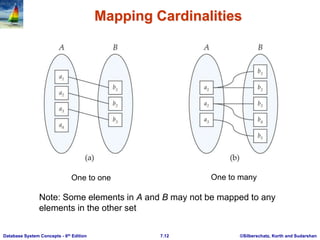
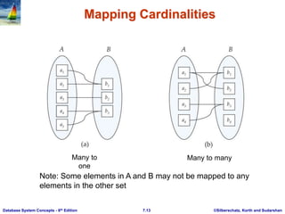
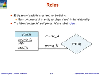
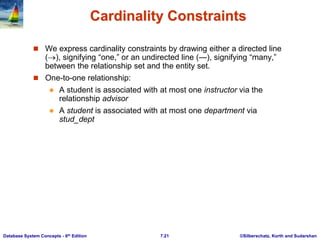
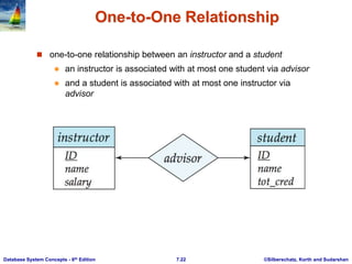
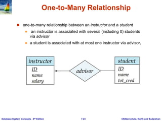
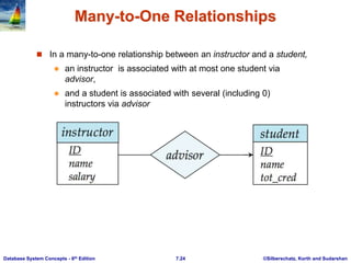
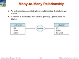
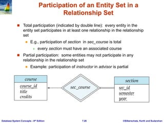
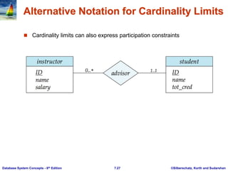
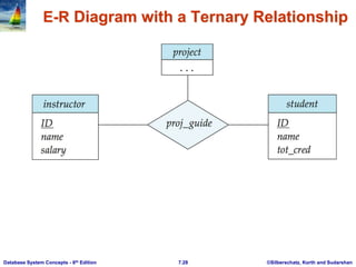
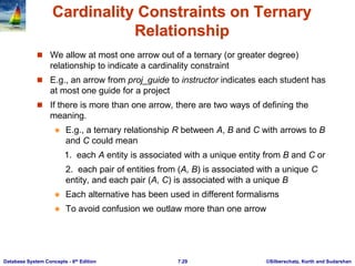
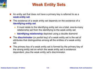
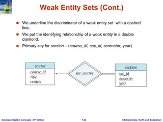
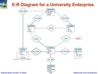
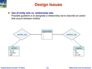
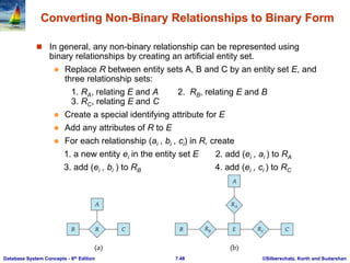
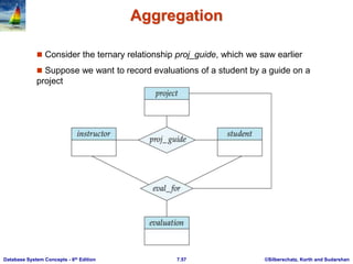
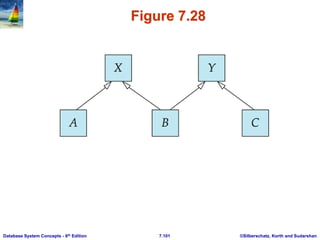
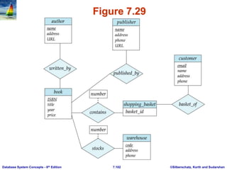
Database System Concepts, 6th Ed.
©Silberschatz, Korth and Sudarshan
See www.db-book.com for conditions on re-use
Chapter 7: Entity-Relationship Model
©Silberschatz, Korth and Sudarshan
7.2
Database System Concepts - 6th Edition
Chapter 7: Entity-Relationship Model
 Design Process
 Modeling
 Constraints
 E-R Diagram
 Design Issues
 Weak Entity Sets
 Extended E-R Features
 Design of the Bank Database
 Reduction to Relation Schemas
 Database Design
 UML
©Silberschatz, Korth and Sudarshan
7.3
Database System Concepts - 6th Edition
Modeling
 A database can be modeled as:
 a collection of entities,
 relationship among entities.
 An entity is an object that exists and is distinguishable from other
objects.
 Example: specific person, company, event, plant
 Entities have attributes
 Example: people have names and addresses
 An entity set is a set of entities of the same type that share the same
properties.
 Example: set of all persons, companies, trees, holidays
©Silberschatz, Korth and Sudarshan
7.4
Database System Concepts - 6th Edition
Entity Sets instructor and student
instructor_ID instructor_name student-ID student_name
©Silberschatz, Korth and Sudarshan
7.5
Database System Concepts - 6th Edition
Relationship Sets
 A relationship is an association among several entities
Example:
44553 (Peltier) advisor 22222 (Einstein)
student entity relationship set instructor entity
 A relationship set is a mathematical relation among n  2 entities, each
taken from entity sets
{(e1, e2, … en) | e1  E1, e2  E2, …, en  En}
where (e1, e2, …, en) is a relationship
 Example:
(44553,22222)  advisor
©Silberschatz, Korth and Sudarshan
7.6
Database System Concepts - 6th Edition
Relationship Set advisor
©Silberschatz, Korth and Sudarshan
7.7
Database System Concepts - 6th Edition
Relationship Sets (Cont.)
 An attribute can also be property of a relationship set.
 For instance, the advisor relationship set between entity sets
instructor and student may have the attribute date which tracks when
the student started being associated with the advisor
©Silberschatz, Korth and Sudarshan
7.8
Database System Concepts - 6th Edition
Degree of a Relationship Set
 binary relationship
 involve two entity sets (or degree two).
 most relationship sets in a database system are binary.
 Relationships between more than two entity sets are rare. Most
relationships are binary. (More on this later.)
 Example: students work on research projects under the
guidance of an instructor.
 relationship proj_guide is a ternary relationship between
instructor, student, and project
©Silberschatz, Korth and Sudarshan
7.9
Database System Concepts - 6th Edition
Attributes
 An entity is represented by a set of attributes, that is descriptive
properties possessed by all members of an entity set.
 Example:
instructor = (ID, name, street, city, salary )
course= (course_id, title, credits)
 Domain – the set of permitted values for each attribute
 Attribute types:
 Simple and composite attributes.
 Single-valued and multivalued attributes
 Example: multivalued attribute: phone_numbers
 Derived attributes
 Can be computed from other attributes
 Example: age, given date_of_birth
©Silberschatz, Korth and Sudarshan
7.10
Database System Concepts - 6th Edition
Composite Attributes
©Silberschatz, Korth and Sudarshan
7.11
Database System Concepts - 6th Edition
Mapping Cardinality Constraints
 Express the number of entities to which another entity can be
associated via a relationship set.
 Most useful in describing binary relationship sets.
 For a binary relationship set the mapping cardinality must be one of
the following types:
 One to one
 One to many
 Many to one
 Many to many
©Silberschatz, Korth and Sudarshan
7.12
Database System Concepts - 6th Edition
Mapping Cardinalities
One to one One to many
Note: Some elements in A and B may not be mapped to any
elements in the other set
©Silberschatz, Korth and Sudarshan
7.13
Database System Concepts - 6th Edition
Mapping Cardinalities
Many to
one
Many to many
Note: Some elements in A and B may not be mapped to any
elements in the other set
©Silberschatz, Korth and Sudarshan
7.14
Database System Concepts - 6th Edition
Keys
 A super key of an entity set is a set of one or more attributes
whose values uniquely determine each entity.
 A candidate key of an entity set is a minimal super key
 ID is candidate key of instructor
 course_id is candidate key of course
 Although several candidate keys may exist, one of the candidate
keys is selected to be the primary key.
©Silberschatz, Korth and Sudarshan
7.15
Database System Concepts - 6th Edition
Keys for Relationship Sets
 The combination of primary keys of the participating entity sets
forms a super key of a relationship set.
 (s_id, i_id) is the super key of advisor
 NOTE: this means a pair of entity sets can have at most one
relationship in a particular relationship set.
 Example: if we wish to track multiple meeting dates between
a student and her advisor, we cannot assume a relationship
for each meeting. We can use a multivalued attribute
though
 Must consider the mapping cardinality of the relationship set when
deciding what are the candidate keys
 Need to consider semantics of relationship set in selecting the
primary key in case of more than one candidate key
©Silberschatz, Korth and Sudarshan
7.16
Database System Concepts - 6th Edition
Redundant Attributes
 Suppose we have entity sets
 instructor, with attributes including dept_name
 department
and a relationship
 inst_dept relating instructor and department
 Attribute dept_name in entity instructor is redundant since there is an
explicit relationship inst_dept which relates instructors to departments
 The attribute replicates information present in the relationship, and
should be removed from instructor
 BUT: when converting back to tables, in some cases the attribute
gets reintroduced, as we will see.
©Silberschatz, Korth and Sudarshan
7.17
Database System Concepts - 6th Edition
E-R Diagrams
 Rectangles represent entity sets.
 Diamonds represent relationship sets.
 Attributes listed inside entity rectangle
 Underline indicates primary key attributes
©Silberschatz, Korth and Sudarshan
7.18
Database System Concepts - 6th Edition
Entity With Composite, Multivalued, and Derived
Attributes
©Silberschatz, Korth and Sudarshan
7.19
Database System Concepts - 6th Edition
Relationship Sets with Attributes
©Silberschatz, Korth and Sudarshan
7.20
Database System Concepts - 6th Edition
Roles
 Entity sets of a relationship need not be distinct
 Each occurrence of an entity set plays a “role” in the relationship
 The labels “course_id” and “prereq_id” are called roles.
©Silberschatz, Korth and Sudarshan
7.21
Database System Concepts - 6th Edition
Cardinality Constraints
 We express cardinality constraints by drawing either a directed line
(), signifying “one,” or an undirected line (—), signifying “many,”
between the relationship set and the entity set.
 One-to-one relationship:
 A student is associated with at most one instructor via the
relationship advisor
 A student is associated with at most one department via
stud_dept
©Silberschatz, Korth and Sudarshan
7.22
Database System Concepts - 6th Edition
One-to-One Relationship
 one-to-one relationship between an instructor and a student
 an instructor is associated with at most one student via advisor
 and a student is associated with at most one instructor via
advisor
©Silberschatz, Korth and Sudarshan
7.23
Database System Concepts - 6th Edition
One-to-Many Relationship
 one-to-many relationship between an instructor and a student
 an instructor is associated with several (including 0) students
via advisor
 a student is associated with at most one instructor via advisor,
©Silberschatz, Korth and Sudarshan
7.24
Database System Concepts - 6th Edition
Many-to-One Relationships
 In a many-to-one relationship between an instructor and a student,
 an instructor is associated with at most one student via
advisor,
 and a student is associated with several (including 0)
instructors via advisor
©Silberschatz, Korth and Sudarshan
7.25
Database System Concepts - 6th Edition
Many-to-Many Relationship
 An instructor is associated with several (possibly 0) students via
advisor
 A student is associated with several (possibly 0) instructors via
advisor
©Silberschatz, Korth and Sudarshan
7.26
Database System Concepts - 6th Edition
Participation of an Entity Set in a
Relationship Set
 Total participation (indicated by double line): every entity in the
entity set participates in at least one relationship in the relationship
set
 E.g., participation of section in sec_course is total
 every section must have an associated course
 Partial participation: some entities may not participate in any
relationship in the relationship set
 Example: participation of instructor in advisor is partial
©Silberschatz, Korth and Sudarshan
7.27
Database System Concepts - 6th Edition
Alternative Notation for Cardinality Limits
 Cardinality limits can also express participation constraints
©Silberschatz, Korth and Sudarshan
7.28
Database System Concepts - 6th Edition
E-R Diagram with a Ternary Relationship
©Silberschatz, Korth and Sudarshan
7.29
Database System Concepts - 6th Edition
Cardinality Constraints on Ternary
Relationship
 We allow at most one arrow out of a ternary (or greater degree)
relationship to indicate a cardinality constraint
 E.g., an arrow from proj_guide to instructor indicates each student has
at most one guide for a project
 If there is more than one arrow, there are two ways of defining the
meaning.
 E.g., a ternary relationship R between A, B and C with arrows to B
and C could mean
1. each A entity is associated with a unique entity from B and C or
2. each pair of entities from (A, B) is associated with a unique C
entity, and each pair (A, C) is associated with a unique B
 Each alternative has been used in different formalisms
 To avoid confusion we outlaw more than one arrow
Database System Concepts, 6th Ed.
©Silberschatz, Korth and Sudarshan
See www.db-book.com for conditions on re-use
How about doing an ER design
interactively on the board?
Suggest an application to be modeled.
©Silberschatz, Korth and Sudarshan
7.31
Database System Concepts - 6th Edition
Weak Entity Sets
 An entity set that does not have a primary key is referred to as a
weak entity set.
 The existence of a weak entity set depends on the existence of a
identifying entity set
 It must relate to the identifying entity set via a total, one-to-many
relationship set from the identifying to the weak entity set
 Identifying relationship depicted using a double diamond
 The discriminator (or partial key) of a weak entity set is the set of
attributes that distinguishes among all the entities of a weak entity
set.
 The primary key of a weak entity set is formed by the primary key of
the strong entity set on which the weak entity set is existence
dependent, plus the weak entity set’s discriminator.
©Silberschatz, Korth and Sudarshan
7.32
Database System Concepts - 6th Edition
Weak Entity Sets (Cont.)
 We underline the discriminator of a weak entity set with a dashed
line.
 We put the identifying relationship of a weak entity in a double
diamond.
 Primary key for section – (course_id, sec_id, semester, year)
©Silberschatz, Korth and Sudarshan
7.33
Database System Concepts - 6th Edition
Weak Entity Sets (Cont.)
 Note: the primary key of the strong entity set is not explicitly stored
with the weak entity set, since it is implicit in the identifying
relationship.
 If course_id were explicitly stored, section could be made a strong
entity, but then the relationship between section and course would
be duplicated by an implicit relationship defined by the attribute
course_id common to course and section
©Silberschatz, Korth and Sudarshan
7.34
Database System Concepts - 6th Edition
E-R Diagram for a University Enterprise
©Silberschatz, Korth and Sudarshan
7.35
Database System Concepts - 6th Edition
Reduction to Relational Schemas
©Silberschatz, Korth and Sudarshan
7.36
Database System Concepts - 6th Edition
Reduction to Relation Schemas
 Entity sets and relationship sets can be expressed uniformly as
relation schemas that represent the contents of the database.
 A database which conforms to an E-R diagram can be represented by
a collection of schemas.
 For each entity set and relationship set there is a unique schema that
is assigned the name of the corresponding entity set or relationship
set.
 Each schema has a number of columns (generally corresponding to
attributes), which have unique names.
©Silberschatz, Korth and Sudarshan
7.37
Database System Concepts - 6th Edition
Representing Entity Sets With Simple
Attributes
 A strong entity set reduces to a schema with the same attributes
student(ID, name, tot_cred)
 A weak entity set becomes a table that includes a column for the primary
key of the identifying strong entity set
section ( course_id, sec_id, sem, year )
©Silberschatz, Korth and Sudarshan
7.38
Database System Concepts - 6th Edition
Representing Relationship Sets
 A many-to-many relationship set is represented as a schema with
attributes for the primary keys of the two participating entity sets, and any
descriptive attributes of the relationship set.
 Example: schema for relationship set advisor
advisor = (s_id, i_id)
©Silberschatz, Korth and Sudarshan
7.39
Database System Concepts - 6th Edition
Redundancy of Schemas
 Many-to-one and one-to-many relationship sets that are total on the
many-side can be represented by adding an extra attribute to the
“many” side, containing the primary key of the “one” side
 Example: Instead of creating a schema for relationship set inst_dept,
add an attribute dept_name to the schema arising from entity set
instructor
©Silberschatz, Korth and Sudarshan
7.40
Database System Concepts - 6th Edition
Redundancy of Schemas (Cont.)
 For one-to-one relationship sets, either side can be chosen to act
as the “many” side
 That is, extra attribute can be added to either of the tables
corresponding to the two entity sets
 If participation is partial on the “many” side, replacing a schema by
an extra attribute in the schema corresponding to the “many” side
could result in null values
 The schema corresponding to a relationship set linking a weak
entity set to its identifying strong entity set is redundant.
 Example: The section schema already contains the attributes
that would appear in the sec_course schema
©Silberschatz, Korth and Sudarshan
7.41
Database System Concepts - 6th Edition
Composite and Multivalued Attributes
 Composite attributes are flattened out by creating a
separate attribute for each component attribute
 Example: given entity set instructor with
composite attribute name with component
attributes first_name and last_name the schema
corresponding to the entity set has two attributes
name_first_name and name_last_name
 Prefix omitted if there is no ambiguity
 Ignoring multivalued attributes, extended instructor
schema is
 instructor(ID,
first_name, middle_initial, last_name,
street_number, street_name,
apt_number, city, state, zip_code,
date_of_birth)
©Silberschatz, Korth and Sudarshan
7.42
Database System Concepts - 6th Edition
Composite and Multivalued Attributes
 A multivalued attribute M of an entity E is represented by a separate
schema EM
 Schema EM has attributes corresponding to the primary key of E
and an attribute corresponding to multivalued attribute M
 Example: Multivalued attribute phone_number of instructor is
represented by a schema:
inst_phone= ( ID, phone_number)
 Each value of the multivalued attribute maps to a separate tuple of
the relation on schema EM
 For example, an instructor entity with primary key 22222 and
phone numbers 456-7890 and 123-4567 maps to two tuples:
(22222, 456-7890) and (22222, 123-4567)
©Silberschatz, Korth and Sudarshan
7.43
Database System Concepts - 6th Edition
Multivalued Attributes (Cont.)
 Special case:entity time_slot has only one attribute other than the
primary-key attribute, and that attribute is multivalued
 Optimization: Don’t create the relation corresponding to the entity,
just create the one corresponding to the multivalued attribute
 time_slot(time_slot_id, day, start_time, end_time)
 Caveat: time_slot attribute of section (from sec_time_slot) cannot be
a foreign key due to this optimization
©Silberschatz, Korth and Sudarshan
7.44
Database System Concepts - 6th Edition
Design Issues
 Use of entity sets vs. attributes
 Use of phone as an entity allows extra information about phone numbers
(plus multiple phone numbers)
©Silberschatz, Korth and Sudarshan
7.45
Database System Concepts - 6th Edition
Design Issues
 Use of entity sets vs. relationship sets
Possible guideline is to designate a relationship set to describe an action
that occurs between entities
©Silberschatz, Korth and Sudarshan
7.46
Database System Concepts - 6th Edition
Design Issues
 Binary versus n-ary relationship sets
Although it is possible to replace any nonbinary (n-ary, for n > 2)
relationship set by a number of distinct binary relationship sets, a n-ary
relationship set shows more clearly that several entities participate in a
single relationship.
 Placement of relationship attributes
e.g., attribute date as attribute of advisor or as attribute of student
©Silberschatz, Korth and Sudarshan
7.47
Database System Concepts - 6th Edition
Binary Vs. Non-Binary Relationships
 Some relationships that appear to be non-binary may be better
represented using binary relationships
 E.g., A ternary relationship parents, relating a child to his/her
father and mother, is best replaced by two binary relationships,
father and mother
 Using two binary relationships allows partial information (e.g.,
only mother being know)
 But there are some relationships that are naturally non-binary
 Example: proj_guide
©Silberschatz, Korth and Sudarshan
7.48
Database System Concepts - 6th Edition
Converting Non-Binary Relationships to Binary Form
 In general, any non-binary relationship can be represented using
binary relationships by creating an artificial entity set.
 Replace R between entity sets A, B and C by an entity set E, and
three relationship sets:
1. RA, relating E and A 2. RB, relating E and B
3. RC, relating E and C
 Create a special identifying attribute for E
 Add any attributes of R to E
 For each relationship (ai , bi , ci) in R, create
1. a new entity ei in the entity set E 2. add (ei , ai ) to RA
3. add (ei , bi ) to RB 4. add (ei , ci ) to RC
©Silberschatz, Korth and Sudarshan
7.49
Database System Concepts - 6th Edition
Converting Non-Binary Relationships
(Cont.)
 Also need to translate constraints
 Translating all constraints may not be possible
 There may be instances in the translated schema that
cannot correspond to any instance of R
 Exercise: add constraints to the relationships RA, RB and
RC to ensure that a newly created entity corresponds to
exactly one entity in each of entity sets A, B and C
 We can avoid creating an identifying attribute by making E a
weak entity set (described shortly) identified by the three
relationship sets
©Silberschatz, Korth and Sudarshan
7.50
Database System Concepts - 6th Edition
Extended ER Features
©Silberschatz, Korth and Sudarshan
7.51
Database System Concepts - 6th Edition
Extended E-R Features: Specialization
 Top-down design process; we designate subgroupings within an entity set
that are distinctive from other entities in the set.
 These subgroupings become lower-level entity sets that have attributes or
participate in relationships that do not apply to the higher-level entity set.
 Depicted by a triangle component labeled ISA (E.g., instructor “is a”
person).
 Attribute inheritance – a lower-level entity set inherits all the attributes
and relationship participation of the higher-level entity set to which it is
linked.
©Silberschatz, Korth and Sudarshan
7.52
Database System Concepts - 6th Edition
Specialization Example
©Silberschatz, Korth and Sudarshan
7.53
Database System Concepts - 6th Edition
Extended ER Features: Generalization
 A bottom-up design process – combine a number of entity sets
that share the same features into a higher-level entity set.
 Specialization and generalization are simple inversions of each
other; they are represented in an E-R diagram in the same way.
 The terms specialization and generalization are used
interchangeably.
©Silberschatz, Korth and Sudarshan
7.54
Database System Concepts - 6th Edition
Specialization and Generalization (Cont.)
 Can have multiple specializations of an entity set based on different
features.
 E.g., permanent_employee vs. temporary_employee, in addition to
instructor vs. secretary
 Each particular employee would be
 a member of one of permanent_employee or temporary_employee,
 and also a member of one of instructor, secretary
 The ISA relationship also referred to as superclass - subclass
relationship
©Silberschatz, Korth and Sudarshan
7.55
Database System Concepts - 6th Edition
Design Constraints on a
Specialization/Generalization
 Constraint on which entities can be members of a given lower-level entity
set.
 condition-defined
 Example: all customers over 65 years are members of senior-
citizen entity set; senior-citizen ISA person.
 user-defined
 Constraint on whether or not entities may belong to more than one lower-
level entity set within a single generalization.
 Disjoint
 an entity can belong to only one lower-level entity set
 Noted in E-R diagram by having multiple lower-level entity sets link
to the same triangle
 Overlapping
 an entity can belong to more than one lower-level entity set
©Silberschatz, Korth and Sudarshan
7.56
Database System Concepts - 6th Edition
Design Constraints on a
Specialization/Generalization (Cont.)
 Completeness constraint -- specifies whether or not an entity in
the higher-level entity set must belong to at least one of the lower-
level entity sets within a generalization.
 total: an entity must belong to one of the lower-level entity sets
 partial: an entity need not belong to one of the lower-level
entity sets
©Silberschatz, Korth and Sudarshan
7.57
Database System Concepts - 6th Edition
Aggregation
 Consider the ternary relationship proj_guide, which we saw earlier
 Suppose we want to record evaluations of a student by a guide on a
project
©Silberschatz, Korth and Sudarshan
7.58
Database System Concepts - 6th Edition
Aggregation (Cont.)
 Relationship sets eval_for and proj_guide represent overlapping
information
 Every eval_for relationship corresponds to a proj_guide
relationship
 However, some proj_guide relationships may not correspond to
any eval_for relationships
 So we can’t discard the proj_guide relationship
 Eliminate this redundancy via aggregation
 Treat relationship as an abstract entity
 Allows relationships between relationships
 Abstraction of relationship into new entity
©Silberschatz, Korth and Sudarshan
7.59
Database System Concepts - 6th Edition
Aggregation (Cont.)
 Without introducing redundancy, the following diagram represents:
 A student is guided by a particular instructor on a particular project
 A student, instructor, project combination may have an associated
evaluation
©Silberschatz, Korth and Sudarshan
7.60
Database System Concepts - 6th Edition
Representing Specialization via
Schemas
 Method 1:
 Form a schema for the higher-level entity
 Form a schema for each lower-level entity set, include primary key
of higher-level entity set and local attributes
schema attributes
person ID, name, street, city
student ID, tot_cred
employee ID, salary
 Drawback: getting information about, an employee requires
accessing two relations, the one corresponding to the low-level
schema and the one corresponding to the high-level schema
©Silberschatz, Korth and Sudarshan
7.61
Database System Concepts - 6th Edition
Representing Specialization as Schemas
(Cont.)
 Method 2:
 Form a schema for each entity set with all local and inherited attributes
schema attributes
person ID, name, street, city
student ID, name, street, city, tot_cred
employee ID, name, street, city, salary
 If specialization is total, the schema for the generalized entity set
(person) not required to store information
 Can be defined as a “view” relation containing union of
specialization relations
 But explicit schema may still be needed for foreign key constraints
 Drawback: name, street and city may be stored redundantly for people
who are both students and employees
©Silberschatz, Korth and Sudarshan
7.62
Database System Concepts - 6th Edition
Schemas Corresponding to Aggregation
 To represent aggregation, create a schema containing
 primary key of the aggregated relationship,
 the primary key of the associated entity set
 any descriptive attributes
©Silberschatz, Korth and Sudarshan
7.63
Database System Concepts - 6th Edition
Schemas Corresponding to
Aggregation (Cont.)
 For example, to represent aggregation manages between
relationship works_on and entity set manager, create a schema
eval_for (s_ID, project_id, i_ID, evaluation_id)
 Schema proj_guide is redundant provided we are willing to store null
values for attribute manager_name in relation on schema manages
©Silberschatz, Korth and Sudarshan
7.64
Database System Concepts - 6th Edition
E-R Design Decisions
 The use of an attribute or entity set to represent an object.
 Whether a real-world concept is best expressed by an entity set or
a relationship set.
 The use of a ternary relationship versus a pair of binary
relationships.
 The use of a strong or weak entity set.
 The use of specialization/generalization – contributes to modularity
in the design.
 The use of aggregation – can treat the aggregate entity set as a
single unit without concern for the details of its internal structure.
Database System Concepts, 6th Ed.
©Silberschatz, Korth and Sudarshan
See www.db-book.com for conditions on re-use
How about doing another ER design
interactively on the board?
©Silberschatz, Korth and Sudarshan
7.66
Database System Concepts - 6th Edition
Summary of Symbols Used in E-R Notation
©Silberschatz, Korth and Sudarshan
7.67
Database System Concepts - 6th Edition
Symbols Used in E-R Notation (Cont.)
©Silberschatz, Korth and Sudarshan
7.68
Database System Concepts - 6th Edition
Alternative ER Notations
 Chen, IDE1FX, …
©Silberschatz, Korth and Sudarshan
7.69
Database System Concepts - 6th Edition
Alternative ER Notations
Chen IDE1FX (Crows feet notation)
©Silberschatz, Korth and Sudarshan
7.70
Database System Concepts - 6th Edition
UML
 UML: Unified Modeling Language
 UML has many components to graphically model different aspects
of an entire software system
 UML Class Diagrams correspond to E-R Diagram, but several
differences.
©Silberschatz, Korth and Sudarshan
7.71
Database System Concepts - 6th Edition
ER vs. UML Class Diagrams
*Note reversal of position in cardinality constraint depiction
©Silberschatz, Korth and Sudarshan
7.72
Database System Concepts - 6th Edition
ER vs. UML Class Diagrams
ER Diagram Notation Equivalent in UML
*Generalization can use merged or separate arrows independent
of disjoint/overlapping
©Silberschatz, Korth and Sudarshan
7.73
Database System Concepts - 6th Edition
UML Class Diagrams (Cont.)
 Binary relationship sets are represented in UML by just drawing a
line connecting the entity sets. The relationship set name is written
adjacent to the line.
 The role played by an entity set in a relationship set may also be
specified by writing the role name on the line, adjacent to the entity
set.
 The relationship set name may alternatively be written in a box,
along with attributes of the relationship set, and the box is
connected, using a dotted line, to the line depicting the relationship
set.
Database System Concepts, 6th Ed.
©Silberschatz, Korth and Sudarshan
See www.db-book.com for conditions on re-use
End of Chapter 7
©Silberschatz, Korth and Sudarshan
7.75
Database System Concepts - 6th Edition
Figure 7.01
©Silberschatz, Korth and Sudarshan
7.76
Database System Concepts - 6th Edition
Figure 7.02
©Silberschatz, Korth and Sudarshan
7.77
Database System Concepts - 6th Edition
Figure 7.03
©Silberschatz, Korth and Sudarshan
7.78
Database System Concepts - 6th Edition
Figure 7.04
©Silberschatz, Korth and Sudarshan
7.79
Database System Concepts - 6th Edition
Figure 7.05
©Silberschatz, Korth and Sudarshan
7.80
Database System Concepts - 6th Edition
Figure 7.06
©Silberschatz, Korth and Sudarshan
7.81
Database System Concepts - 6th Edition
Figure 7.07
©Silberschatz, Korth and Sudarshan
7.82
Database System Concepts - 6th Edition
Figure 7.08
©Silberschatz, Korth and Sudarshan
7.83
Database System Concepts - 6th Edition
Figure 7.09
©Silberschatz, Korth and Sudarshan
7.84
Database System Concepts - 6th Edition
Figure 7.10
©Silberschatz, Korth and Sudarshan
7.85
Database System Concepts - 6th Edition
Figure 7.11
©Silberschatz, Korth and Sudarshan
7.86
Database System Concepts - 6th Edition
Figure 7.12
©Silberschatz, Korth and Sudarshan
7.87
Database System Concepts - 6th Edition
Figure 7.13
©Silberschatz, Korth and Sudarshan
7.88
Database System Concepts - 6th Edition
Figure 7.14
©Silberschatz, Korth and Sudarshan
7.89
Database System Concepts - 6th Edition
Figure 7.15
©Silberschatz, Korth and Sudarshan
7.90
Database System Concepts - 6th Edition
Figure 7.17
©Silberschatz, Korth and Sudarshan
7.91
Database System Concepts - 6th Edition
Figure 7.18
©Silberschatz, Korth and Sudarshan
7.92
Database System Concepts - 6th Edition
Figure 7.19
©Silberschatz, Korth and Sudarshan
7.93
Database System Concepts - 6th Edition
Figure 7.20
©Silberschatz, Korth and Sudarshan
7.94
Database System Concepts - 6th Edition
Figure 7.21
©Silberschatz, Korth and Sudarshan
7.95
Database System Concepts - 6th Edition
Figure 7.22
©Silberschatz, Korth and Sudarshan
7.96
Database System Concepts - 6th Edition
Figure 7.23
©Silberschatz, Korth and Sudarshan
7.97
Database System Concepts - 6th Edition
Figure 7.24
©Silberschatz, Korth and Sudarshan
7.98
Database System Concepts - 6th Edition
Figure 7.25
©Silberschatz, Korth and Sudarshan
7.99
Database System Concepts - 6th Edition
Figure 7.26
©Silberschatz, Korth and Sudarshan
7.100
Database System Concepts - 6th Edition
Figure 7.27
©Silberschatz, Korth and Sudarshan
7.101
Database System Concepts - 6th Edition
Figure 7.28
©Silberschatz, Korth and Sudarshan
7.102
Database System Concepts - 6th Edition
Figure 7.29

ch7.ppt ER Model lecture 102 slides set in ppt

  • 1.
    Database System Concepts,6th Ed. ©Silberschatz, Korth and Sudarshan See www.db-book.com for conditions on re-use Chapter 7: Entity-Relationship Model
  • 2.
    ©Silberschatz, Korth andSudarshan 7.2 Database System Concepts - 6th Edition Chapter 7: Entity-Relationship Model  Design Process  Modeling  Constraints  E-R Diagram  Design Issues  Weak Entity Sets  Extended E-R Features  Design of the Bank Database  Reduction to Relation Schemas  Database Design  UML
  • 3.
    ©Silberschatz, Korth andSudarshan 7.3 Database System Concepts - 6th Edition Modeling  A database can be modeled as:  a collection of entities,  relationship among entities.  An entity is an object that exists and is distinguishable from other objects.  Example: specific person, company, event, plant  Entities have attributes  Example: people have names and addresses  An entity set is a set of entities of the same type that share the same properties.  Example: set of all persons, companies, trees, holidays
  • 4.
    ©Silberschatz, Korth andSudarshan 7.4 Database System Concepts - 6th Edition Entity Sets instructor and student instructor_ID instructor_name student-ID student_name
  • 5.
    ©Silberschatz, Korth andSudarshan 7.5 Database System Concepts - 6th Edition Relationship Sets  A relationship is an association among several entities Example: 44553 (Peltier) advisor 22222 (Einstein) student entity relationship set instructor entity  A relationship set is a mathematical relation among n  2 entities, each taken from entity sets {(e1, e2, … en) | e1  E1, e2  E2, …, en  En} where (e1, e2, …, en) is a relationship  Example: (44553,22222)  advisor
  • 6.
    ©Silberschatz, Korth andSudarshan 7.6 Database System Concepts - 6th Edition Relationship Set advisor
  • 7.
    ©Silberschatz, Korth andSudarshan 7.7 Database System Concepts - 6th Edition Relationship Sets (Cont.)  An attribute can also be property of a relationship set.  For instance, the advisor relationship set between entity sets instructor and student may have the attribute date which tracks when the student started being associated with the advisor
  • 8.
    ©Silberschatz, Korth andSudarshan 7.8 Database System Concepts - 6th Edition Degree of a Relationship Set  binary relationship  involve two entity sets (or degree two).  most relationship sets in a database system are binary.  Relationships between more than two entity sets are rare. Most relationships are binary. (More on this later.)  Example: students work on research projects under the guidance of an instructor.  relationship proj_guide is a ternary relationship between instructor, student, and project
  • 9.
    ©Silberschatz, Korth andSudarshan 7.9 Database System Concepts - 6th Edition Attributes  An entity is represented by a set of attributes, that is descriptive properties possessed by all members of an entity set.  Example: instructor = (ID, name, street, city, salary ) course= (course_id, title, credits)  Domain – the set of permitted values for each attribute  Attribute types:  Simple and composite attributes.  Single-valued and multivalued attributes  Example: multivalued attribute: phone_numbers  Derived attributes  Can be computed from other attributes  Example: age, given date_of_birth
  • 10.
    ©Silberschatz, Korth andSudarshan 7.10 Database System Concepts - 6th Edition Composite Attributes
  • 11.
    ©Silberschatz, Korth andSudarshan 7.11 Database System Concepts - 6th Edition Mapping Cardinality Constraints  Express the number of entities to which another entity can be associated via a relationship set.  Most useful in describing binary relationship sets.  For a binary relationship set the mapping cardinality must be one of the following types:  One to one  One to many  Many to one  Many to many
  • 12.
    ©Silberschatz, Korth andSudarshan 7.12 Database System Concepts - 6th Edition Mapping Cardinalities One to one One to many Note: Some elements in A and B may not be mapped to any elements in the other set
  • 13.
    ©Silberschatz, Korth andSudarshan 7.13 Database System Concepts - 6th Edition Mapping Cardinalities Many to one Many to many Note: Some elements in A and B may not be mapped to any elements in the other set
  • 14.
    ©Silberschatz, Korth andSudarshan 7.14 Database System Concepts - 6th Edition Keys  A super key of an entity set is a set of one or more attributes whose values uniquely determine each entity.  A candidate key of an entity set is a minimal super key  ID is candidate key of instructor  course_id is candidate key of course  Although several candidate keys may exist, one of the candidate keys is selected to be the primary key.
  • 15.
    ©Silberschatz, Korth andSudarshan 7.15 Database System Concepts - 6th Edition Keys for Relationship Sets  The combination of primary keys of the participating entity sets forms a super key of a relationship set.  (s_id, i_id) is the super key of advisor  NOTE: this means a pair of entity sets can have at most one relationship in a particular relationship set.  Example: if we wish to track multiple meeting dates between a student and her advisor, we cannot assume a relationship for each meeting. We can use a multivalued attribute though  Must consider the mapping cardinality of the relationship set when deciding what are the candidate keys  Need to consider semantics of relationship set in selecting the primary key in case of more than one candidate key
  • 16.
    ©Silberschatz, Korth andSudarshan 7.16 Database System Concepts - 6th Edition Redundant Attributes  Suppose we have entity sets  instructor, with attributes including dept_name  department and a relationship  inst_dept relating instructor and department  Attribute dept_name in entity instructor is redundant since there is an explicit relationship inst_dept which relates instructors to departments  The attribute replicates information present in the relationship, and should be removed from instructor  BUT: when converting back to tables, in some cases the attribute gets reintroduced, as we will see.
  • 17.
    ©Silberschatz, Korth andSudarshan 7.17 Database System Concepts - 6th Edition E-R Diagrams  Rectangles represent entity sets.  Diamonds represent relationship sets.  Attributes listed inside entity rectangle  Underline indicates primary key attributes
  • 18.
    ©Silberschatz, Korth andSudarshan 7.18 Database System Concepts - 6th Edition Entity With Composite, Multivalued, and Derived Attributes
  • 19.
    ©Silberschatz, Korth andSudarshan 7.19 Database System Concepts - 6th Edition Relationship Sets with Attributes
  • 20.
    ©Silberschatz, Korth andSudarshan 7.20 Database System Concepts - 6th Edition Roles  Entity sets of a relationship need not be distinct  Each occurrence of an entity set plays a “role” in the relationship  The labels “course_id” and “prereq_id” are called roles.
  • 21.
    ©Silberschatz, Korth andSudarshan 7.21 Database System Concepts - 6th Edition Cardinality Constraints  We express cardinality constraints by drawing either a directed line (), signifying “one,” or an undirected line (—), signifying “many,” between the relationship set and the entity set.  One-to-one relationship:  A student is associated with at most one instructor via the relationship advisor  A student is associated with at most one department via stud_dept
  • 22.
    ©Silberschatz, Korth andSudarshan 7.22 Database System Concepts - 6th Edition One-to-One Relationship  one-to-one relationship between an instructor and a student  an instructor is associated with at most one student via advisor  and a student is associated with at most one instructor via advisor
  • 23.
    ©Silberschatz, Korth andSudarshan 7.23 Database System Concepts - 6th Edition One-to-Many Relationship  one-to-many relationship between an instructor and a student  an instructor is associated with several (including 0) students via advisor  a student is associated with at most one instructor via advisor,
  • 24.
    ©Silberschatz, Korth andSudarshan 7.24 Database System Concepts - 6th Edition Many-to-One Relationships  In a many-to-one relationship between an instructor and a student,  an instructor is associated with at most one student via advisor,  and a student is associated with several (including 0) instructors via advisor
  • 25.
    ©Silberschatz, Korth andSudarshan 7.25 Database System Concepts - 6th Edition Many-to-Many Relationship  An instructor is associated with several (possibly 0) students via advisor  A student is associated with several (possibly 0) instructors via advisor
  • 26.
    ©Silberschatz, Korth andSudarshan 7.26 Database System Concepts - 6th Edition Participation of an Entity Set in a Relationship Set  Total participation (indicated by double line): every entity in the entity set participates in at least one relationship in the relationship set  E.g., participation of section in sec_course is total  every section must have an associated course  Partial participation: some entities may not participate in any relationship in the relationship set  Example: participation of instructor in advisor is partial
  • 27.
    ©Silberschatz, Korth andSudarshan 7.27 Database System Concepts - 6th Edition Alternative Notation for Cardinality Limits  Cardinality limits can also express participation constraints
  • 28.
    ©Silberschatz, Korth andSudarshan 7.28 Database System Concepts - 6th Edition E-R Diagram with a Ternary Relationship
  • 29.
    ©Silberschatz, Korth andSudarshan 7.29 Database System Concepts - 6th Edition Cardinality Constraints on Ternary Relationship  We allow at most one arrow out of a ternary (or greater degree) relationship to indicate a cardinality constraint  E.g., an arrow from proj_guide to instructor indicates each student has at most one guide for a project  If there is more than one arrow, there are two ways of defining the meaning.  E.g., a ternary relationship R between A, B and C with arrows to B and C could mean 1. each A entity is associated with a unique entity from B and C or 2. each pair of entities from (A, B) is associated with a unique C entity, and each pair (A, C) is associated with a unique B  Each alternative has been used in different formalisms  To avoid confusion we outlaw more than one arrow
  • 30.
    Database System Concepts,6th Ed. ©Silberschatz, Korth and Sudarshan See www.db-book.com for conditions on re-use How about doing an ER design interactively on the board? Suggest an application to be modeled.
  • 31.
    ©Silberschatz, Korth andSudarshan 7.31 Database System Concepts - 6th Edition Weak Entity Sets  An entity set that does not have a primary key is referred to as a weak entity set.  The existence of a weak entity set depends on the existence of a identifying entity set  It must relate to the identifying entity set via a total, one-to-many relationship set from the identifying to the weak entity set  Identifying relationship depicted using a double diamond  The discriminator (or partial key) of a weak entity set is the set of attributes that distinguishes among all the entities of a weak entity set.  The primary key of a weak entity set is formed by the primary key of the strong entity set on which the weak entity set is existence dependent, plus the weak entity set’s discriminator.
  • 32.
    ©Silberschatz, Korth andSudarshan 7.32 Database System Concepts - 6th Edition Weak Entity Sets (Cont.)  We underline the discriminator of a weak entity set with a dashed line.  We put the identifying relationship of a weak entity in a double diamond.  Primary key for section – (course_id, sec_id, semester, year)
  • 33.
    ©Silberschatz, Korth andSudarshan 7.33 Database System Concepts - 6th Edition Weak Entity Sets (Cont.)  Note: the primary key of the strong entity set is not explicitly stored with the weak entity set, since it is implicit in the identifying relationship.  If course_id were explicitly stored, section could be made a strong entity, but then the relationship between section and course would be duplicated by an implicit relationship defined by the attribute course_id common to course and section
  • 34.
    ©Silberschatz, Korth andSudarshan 7.34 Database System Concepts - 6th Edition E-R Diagram for a University Enterprise
  • 35.
    ©Silberschatz, Korth andSudarshan 7.35 Database System Concepts - 6th Edition Reduction to Relational Schemas
  • 36.
    ©Silberschatz, Korth andSudarshan 7.36 Database System Concepts - 6th Edition Reduction to Relation Schemas  Entity sets and relationship sets can be expressed uniformly as relation schemas that represent the contents of the database.  A database which conforms to an E-R diagram can be represented by a collection of schemas.  For each entity set and relationship set there is a unique schema that is assigned the name of the corresponding entity set or relationship set.  Each schema has a number of columns (generally corresponding to attributes), which have unique names.
  • 37.
    ©Silberschatz, Korth andSudarshan 7.37 Database System Concepts - 6th Edition Representing Entity Sets With Simple Attributes  A strong entity set reduces to a schema with the same attributes student(ID, name, tot_cred)  A weak entity set becomes a table that includes a column for the primary key of the identifying strong entity set section ( course_id, sec_id, sem, year )
  • 38.
    ©Silberschatz, Korth andSudarshan 7.38 Database System Concepts - 6th Edition Representing Relationship Sets  A many-to-many relationship set is represented as a schema with attributes for the primary keys of the two participating entity sets, and any descriptive attributes of the relationship set.  Example: schema for relationship set advisor advisor = (s_id, i_id)
  • 39.
    ©Silberschatz, Korth andSudarshan 7.39 Database System Concepts - 6th Edition Redundancy of Schemas  Many-to-one and one-to-many relationship sets that are total on the many-side can be represented by adding an extra attribute to the “many” side, containing the primary key of the “one” side  Example: Instead of creating a schema for relationship set inst_dept, add an attribute dept_name to the schema arising from entity set instructor
  • 40.
    ©Silberschatz, Korth andSudarshan 7.40 Database System Concepts - 6th Edition Redundancy of Schemas (Cont.)  For one-to-one relationship sets, either side can be chosen to act as the “many” side  That is, extra attribute can be added to either of the tables corresponding to the two entity sets  If participation is partial on the “many” side, replacing a schema by an extra attribute in the schema corresponding to the “many” side could result in null values  The schema corresponding to a relationship set linking a weak entity set to its identifying strong entity set is redundant.  Example: The section schema already contains the attributes that would appear in the sec_course schema
  • 41.
    ©Silberschatz, Korth andSudarshan 7.41 Database System Concepts - 6th Edition Composite and Multivalued Attributes  Composite attributes are flattened out by creating a separate attribute for each component attribute  Example: given entity set instructor with composite attribute name with component attributes first_name and last_name the schema corresponding to the entity set has two attributes name_first_name and name_last_name  Prefix omitted if there is no ambiguity  Ignoring multivalued attributes, extended instructor schema is  instructor(ID, first_name, middle_initial, last_name, street_number, street_name, apt_number, city, state, zip_code, date_of_birth)
  • 42.
    ©Silberschatz, Korth andSudarshan 7.42 Database System Concepts - 6th Edition Composite and Multivalued Attributes  A multivalued attribute M of an entity E is represented by a separate schema EM  Schema EM has attributes corresponding to the primary key of E and an attribute corresponding to multivalued attribute M  Example: Multivalued attribute phone_number of instructor is represented by a schema: inst_phone= ( ID, phone_number)  Each value of the multivalued attribute maps to a separate tuple of the relation on schema EM  For example, an instructor entity with primary key 22222 and phone numbers 456-7890 and 123-4567 maps to two tuples: (22222, 456-7890) and (22222, 123-4567)
  • 43.
    ©Silberschatz, Korth andSudarshan 7.43 Database System Concepts - 6th Edition Multivalued Attributes (Cont.)  Special case:entity time_slot has only one attribute other than the primary-key attribute, and that attribute is multivalued  Optimization: Don’t create the relation corresponding to the entity, just create the one corresponding to the multivalued attribute  time_slot(time_slot_id, day, start_time, end_time)  Caveat: time_slot attribute of section (from sec_time_slot) cannot be a foreign key due to this optimization
  • 44.
    ©Silberschatz, Korth andSudarshan 7.44 Database System Concepts - 6th Edition Design Issues  Use of entity sets vs. attributes  Use of phone as an entity allows extra information about phone numbers (plus multiple phone numbers)
  • 45.
    ©Silberschatz, Korth andSudarshan 7.45 Database System Concepts - 6th Edition Design Issues  Use of entity sets vs. relationship sets Possible guideline is to designate a relationship set to describe an action that occurs between entities
  • 46.
    ©Silberschatz, Korth andSudarshan 7.46 Database System Concepts - 6th Edition Design Issues  Binary versus n-ary relationship sets Although it is possible to replace any nonbinary (n-ary, for n > 2) relationship set by a number of distinct binary relationship sets, a n-ary relationship set shows more clearly that several entities participate in a single relationship.  Placement of relationship attributes e.g., attribute date as attribute of advisor or as attribute of student
  • 47.
    ©Silberschatz, Korth andSudarshan 7.47 Database System Concepts - 6th Edition Binary Vs. Non-Binary Relationships  Some relationships that appear to be non-binary may be better represented using binary relationships  E.g., A ternary relationship parents, relating a child to his/her father and mother, is best replaced by two binary relationships, father and mother  Using two binary relationships allows partial information (e.g., only mother being know)  But there are some relationships that are naturally non-binary  Example: proj_guide
  • 48.
    ©Silberschatz, Korth andSudarshan 7.48 Database System Concepts - 6th Edition Converting Non-Binary Relationships to Binary Form  In general, any non-binary relationship can be represented using binary relationships by creating an artificial entity set.  Replace R between entity sets A, B and C by an entity set E, and three relationship sets: 1. RA, relating E and A 2. RB, relating E and B 3. RC, relating E and C  Create a special identifying attribute for E  Add any attributes of R to E  For each relationship (ai , bi , ci) in R, create 1. a new entity ei in the entity set E 2. add (ei , ai ) to RA 3. add (ei , bi ) to RB 4. add (ei , ci ) to RC
  • 49.
    ©Silberschatz, Korth andSudarshan 7.49 Database System Concepts - 6th Edition Converting Non-Binary Relationships (Cont.)  Also need to translate constraints  Translating all constraints may not be possible  There may be instances in the translated schema that cannot correspond to any instance of R  Exercise: add constraints to the relationships RA, RB and RC to ensure that a newly created entity corresponds to exactly one entity in each of entity sets A, B and C  We can avoid creating an identifying attribute by making E a weak entity set (described shortly) identified by the three relationship sets
  • 50.
    ©Silberschatz, Korth andSudarshan 7.50 Database System Concepts - 6th Edition Extended ER Features
  • 51.
    ©Silberschatz, Korth andSudarshan 7.51 Database System Concepts - 6th Edition Extended E-R Features: Specialization  Top-down design process; we designate subgroupings within an entity set that are distinctive from other entities in the set.  These subgroupings become lower-level entity sets that have attributes or participate in relationships that do not apply to the higher-level entity set.  Depicted by a triangle component labeled ISA (E.g., instructor “is a” person).  Attribute inheritance – a lower-level entity set inherits all the attributes and relationship participation of the higher-level entity set to which it is linked.
  • 52.
    ©Silberschatz, Korth andSudarshan 7.52 Database System Concepts - 6th Edition Specialization Example
  • 53.
    ©Silberschatz, Korth andSudarshan 7.53 Database System Concepts - 6th Edition Extended ER Features: Generalization  A bottom-up design process – combine a number of entity sets that share the same features into a higher-level entity set.  Specialization and generalization are simple inversions of each other; they are represented in an E-R diagram in the same way.  The terms specialization and generalization are used interchangeably.
  • 54.
    ©Silberschatz, Korth andSudarshan 7.54 Database System Concepts - 6th Edition Specialization and Generalization (Cont.)  Can have multiple specializations of an entity set based on different features.  E.g., permanent_employee vs. temporary_employee, in addition to instructor vs. secretary  Each particular employee would be  a member of one of permanent_employee or temporary_employee,  and also a member of one of instructor, secretary  The ISA relationship also referred to as superclass - subclass relationship
  • 55.
    ©Silberschatz, Korth andSudarshan 7.55 Database System Concepts - 6th Edition Design Constraints on a Specialization/Generalization  Constraint on which entities can be members of a given lower-level entity set.  condition-defined  Example: all customers over 65 years are members of senior- citizen entity set; senior-citizen ISA person.  user-defined  Constraint on whether or not entities may belong to more than one lower- level entity set within a single generalization.  Disjoint  an entity can belong to only one lower-level entity set  Noted in E-R diagram by having multiple lower-level entity sets link to the same triangle  Overlapping  an entity can belong to more than one lower-level entity set
  • 56.
    ©Silberschatz, Korth andSudarshan 7.56 Database System Concepts - 6th Edition Design Constraints on a Specialization/Generalization (Cont.)  Completeness constraint -- specifies whether or not an entity in the higher-level entity set must belong to at least one of the lower- level entity sets within a generalization.  total: an entity must belong to one of the lower-level entity sets  partial: an entity need not belong to one of the lower-level entity sets
  • 57.
    ©Silberschatz, Korth andSudarshan 7.57 Database System Concepts - 6th Edition Aggregation  Consider the ternary relationship proj_guide, which we saw earlier  Suppose we want to record evaluations of a student by a guide on a project
  • 58.
    ©Silberschatz, Korth andSudarshan 7.58 Database System Concepts - 6th Edition Aggregation (Cont.)  Relationship sets eval_for and proj_guide represent overlapping information  Every eval_for relationship corresponds to a proj_guide relationship  However, some proj_guide relationships may not correspond to any eval_for relationships  So we can’t discard the proj_guide relationship  Eliminate this redundancy via aggregation  Treat relationship as an abstract entity  Allows relationships between relationships  Abstraction of relationship into new entity
  • 59.
    ©Silberschatz, Korth andSudarshan 7.59 Database System Concepts - 6th Edition Aggregation (Cont.)  Without introducing redundancy, the following diagram represents:  A student is guided by a particular instructor on a particular project  A student, instructor, project combination may have an associated evaluation
  • 60.
    ©Silberschatz, Korth andSudarshan 7.60 Database System Concepts - 6th Edition Representing Specialization via Schemas  Method 1:  Form a schema for the higher-level entity  Form a schema for each lower-level entity set, include primary key of higher-level entity set and local attributes schema attributes person ID, name, street, city student ID, tot_cred employee ID, salary  Drawback: getting information about, an employee requires accessing two relations, the one corresponding to the low-level schema and the one corresponding to the high-level schema
  • 61.
    ©Silberschatz, Korth andSudarshan 7.61 Database System Concepts - 6th Edition Representing Specialization as Schemas (Cont.)  Method 2:  Form a schema for each entity set with all local and inherited attributes schema attributes person ID, name, street, city student ID, name, street, city, tot_cred employee ID, name, street, city, salary  If specialization is total, the schema for the generalized entity set (person) not required to store information  Can be defined as a “view” relation containing union of specialization relations  But explicit schema may still be needed for foreign key constraints  Drawback: name, street and city may be stored redundantly for people who are both students and employees
  • 62.
    ©Silberschatz, Korth andSudarshan 7.62 Database System Concepts - 6th Edition Schemas Corresponding to Aggregation  To represent aggregation, create a schema containing  primary key of the aggregated relationship,  the primary key of the associated entity set  any descriptive attributes
  • 63.
    ©Silberschatz, Korth andSudarshan 7.63 Database System Concepts - 6th Edition Schemas Corresponding to Aggregation (Cont.)  For example, to represent aggregation manages between relationship works_on and entity set manager, create a schema eval_for (s_ID, project_id, i_ID, evaluation_id)  Schema proj_guide is redundant provided we are willing to store null values for attribute manager_name in relation on schema manages
  • 64.
    ©Silberschatz, Korth andSudarshan 7.64 Database System Concepts - 6th Edition E-R Design Decisions  The use of an attribute or entity set to represent an object.  Whether a real-world concept is best expressed by an entity set or a relationship set.  The use of a ternary relationship versus a pair of binary relationships.  The use of a strong or weak entity set.  The use of specialization/generalization – contributes to modularity in the design.  The use of aggregation – can treat the aggregate entity set as a single unit without concern for the details of its internal structure.
  • 65.
    Database System Concepts,6th Ed. ©Silberschatz, Korth and Sudarshan See www.db-book.com for conditions on re-use How about doing another ER design interactively on the board?
  • 66.
    ©Silberschatz, Korth andSudarshan 7.66 Database System Concepts - 6th Edition Summary of Symbols Used in E-R Notation
  • 67.
    ©Silberschatz, Korth andSudarshan 7.67 Database System Concepts - 6th Edition Symbols Used in E-R Notation (Cont.)
  • 68.
    ©Silberschatz, Korth andSudarshan 7.68 Database System Concepts - 6th Edition Alternative ER Notations  Chen, IDE1FX, …
  • 69.
    ©Silberschatz, Korth andSudarshan 7.69 Database System Concepts - 6th Edition Alternative ER Notations Chen IDE1FX (Crows feet notation)
  • 70.
    ©Silberschatz, Korth andSudarshan 7.70 Database System Concepts - 6th Edition UML  UML: Unified Modeling Language  UML has many components to graphically model different aspects of an entire software system  UML Class Diagrams correspond to E-R Diagram, but several differences.
  • 71.
    ©Silberschatz, Korth andSudarshan 7.71 Database System Concepts - 6th Edition ER vs. UML Class Diagrams *Note reversal of position in cardinality constraint depiction
  • 72.
    ©Silberschatz, Korth andSudarshan 7.72 Database System Concepts - 6th Edition ER vs. UML Class Diagrams ER Diagram Notation Equivalent in UML *Generalization can use merged or separate arrows independent of disjoint/overlapping
  • 73.
    ©Silberschatz, Korth andSudarshan 7.73 Database System Concepts - 6th Edition UML Class Diagrams (Cont.)  Binary relationship sets are represented in UML by just drawing a line connecting the entity sets. The relationship set name is written adjacent to the line.  The role played by an entity set in a relationship set may also be specified by writing the role name on the line, adjacent to the entity set.  The relationship set name may alternatively be written in a box, along with attributes of the relationship set, and the box is connected, using a dotted line, to the line depicting the relationship set.
  • 74.
    Database System Concepts,6th Ed. ©Silberschatz, Korth and Sudarshan See www.db-book.com for conditions on re-use End of Chapter 7
  • 75.
    ©Silberschatz, Korth andSudarshan 7.75 Database System Concepts - 6th Edition Figure 7.01
  • 76.
    ©Silberschatz, Korth andSudarshan 7.76 Database System Concepts - 6th Edition Figure 7.02
  • 77.
    ©Silberschatz, Korth andSudarshan 7.77 Database System Concepts - 6th Edition Figure 7.03
  • 78.
    ©Silberschatz, Korth andSudarshan 7.78 Database System Concepts - 6th Edition Figure 7.04
  • 79.
    ©Silberschatz, Korth andSudarshan 7.79 Database System Concepts - 6th Edition Figure 7.05
  • 80.
    ©Silberschatz, Korth andSudarshan 7.80 Database System Concepts - 6th Edition Figure 7.06
  • 81.
    ©Silberschatz, Korth andSudarshan 7.81 Database System Concepts - 6th Edition Figure 7.07
  • 82.
    ©Silberschatz, Korth andSudarshan 7.82 Database System Concepts - 6th Edition Figure 7.08
  • 83.
    ©Silberschatz, Korth andSudarshan 7.83 Database System Concepts - 6th Edition Figure 7.09
  • 84.
    ©Silberschatz, Korth andSudarshan 7.84 Database System Concepts - 6th Edition Figure 7.10
  • 85.
    ©Silberschatz, Korth andSudarshan 7.85 Database System Concepts - 6th Edition Figure 7.11
  • 86.
    ©Silberschatz, Korth andSudarshan 7.86 Database System Concepts - 6th Edition Figure 7.12
  • 87.
    ©Silberschatz, Korth andSudarshan 7.87 Database System Concepts - 6th Edition Figure 7.13
  • 88.
    ©Silberschatz, Korth andSudarshan 7.88 Database System Concepts - 6th Edition Figure 7.14
  • 89.
    ©Silberschatz, Korth andSudarshan 7.89 Database System Concepts - 6th Edition Figure 7.15
  • 90.
    ©Silberschatz, Korth andSudarshan 7.90 Database System Concepts - 6th Edition Figure 7.17
  • 91.
    ©Silberschatz, Korth andSudarshan 7.91 Database System Concepts - 6th Edition Figure 7.18
  • 92.
    ©Silberschatz, Korth andSudarshan 7.92 Database System Concepts - 6th Edition Figure 7.19
  • 93.
    ©Silberschatz, Korth andSudarshan 7.93 Database System Concepts - 6th Edition Figure 7.20
  • 94.
    ©Silberschatz, Korth andSudarshan 7.94 Database System Concepts - 6th Edition Figure 7.21
  • 95.
    ©Silberschatz, Korth andSudarshan 7.95 Database System Concepts - 6th Edition Figure 7.22
  • 96.
    ©Silberschatz, Korth andSudarshan 7.96 Database System Concepts - 6th Edition Figure 7.23
  • 97.
    ©Silberschatz, Korth andSudarshan 7.97 Database System Concepts - 6th Edition Figure 7.24
  • 98.
    ©Silberschatz, Korth andSudarshan 7.98 Database System Concepts - 6th Edition Figure 7.25
  • 99.
    ©Silberschatz, Korth andSudarshan 7.99 Database System Concepts - 6th Edition Figure 7.26
  • 100.
    ©Silberschatz, Korth andSudarshan 7.100 Database System Concepts - 6th Edition Figure 7.27
  • 101.
    ©Silberschatz, Korth andSudarshan 7.101 Database System Concepts - 6th Edition Figure 7.28
  • 102.
    ©Silberschatz, Korth andSudarshan 7.102 Database System Concepts - 6th Edition Figure 7.29