Download to read offline


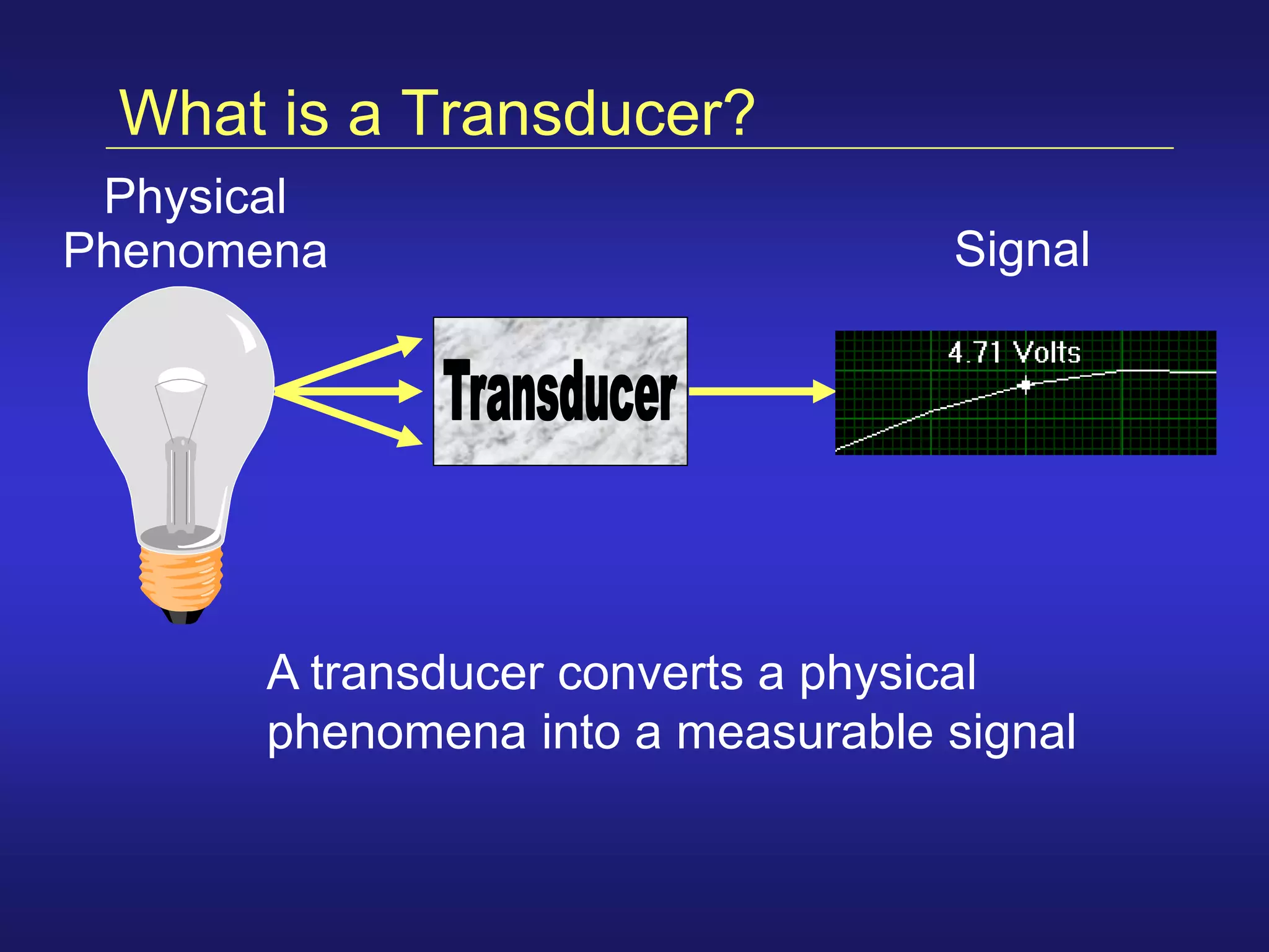
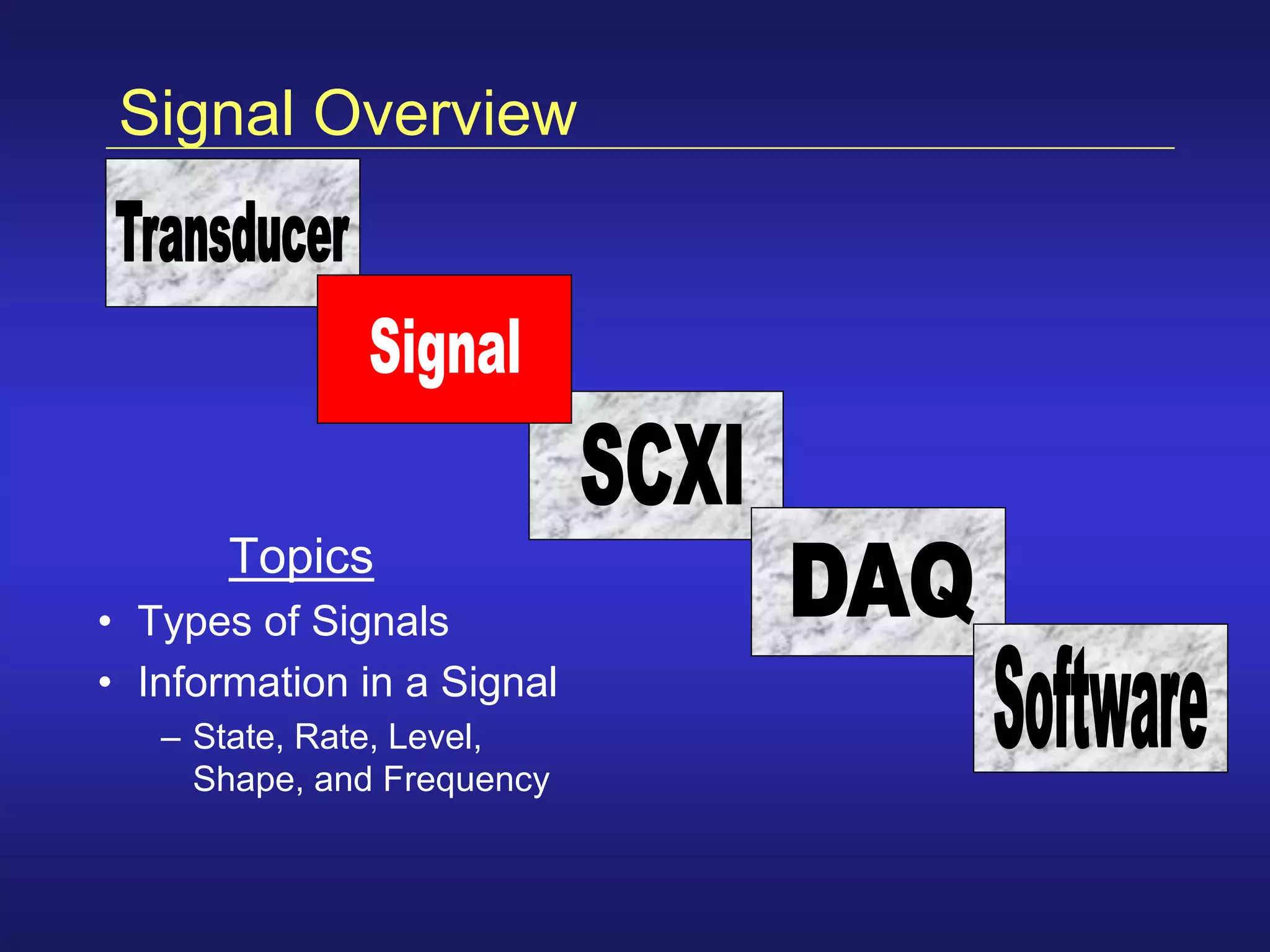


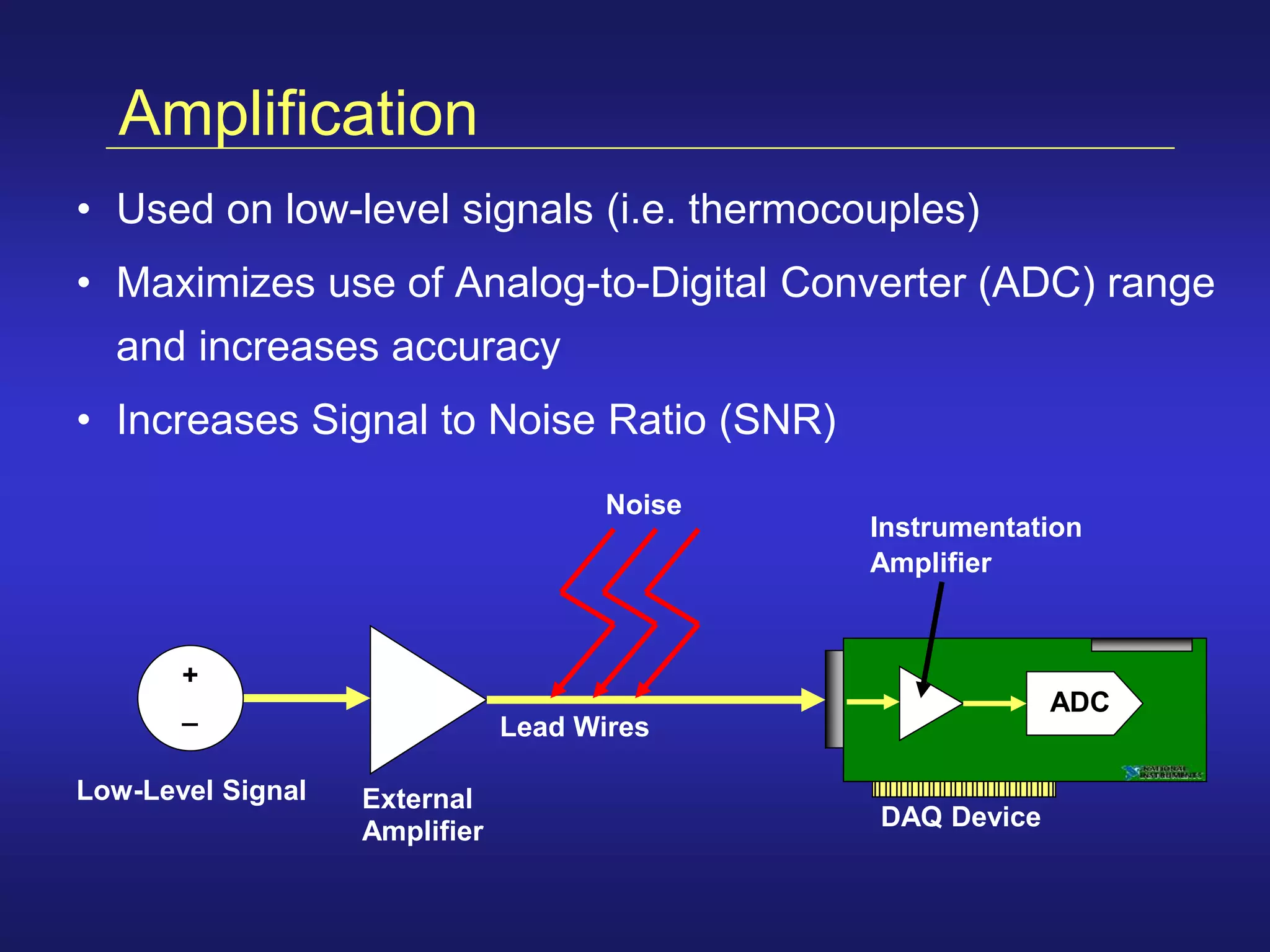


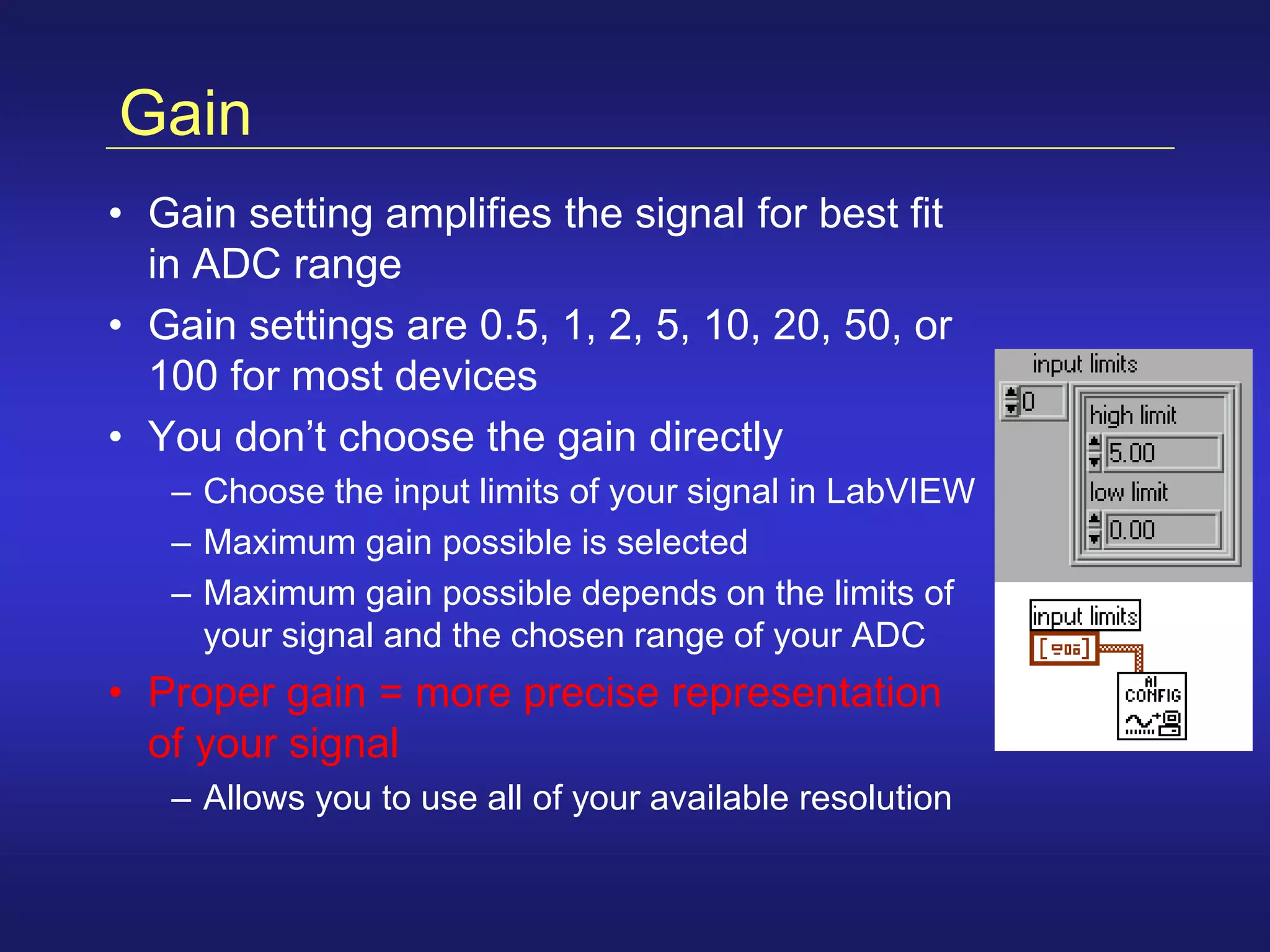


This document provides an overview of data acquisition concepts including transducers, signals, signal conditioning, and DAQ hardware. It discusses how transducers convert physical phenomena into measurable signals, the differences between analog and digital signals, and common signal conditioning techniques like amplification. It also describes common components of DAQ devices, and considerations for configuring devices like resolution, range, gain, and code width to optimize measurement precision.


![ict_presentation_final_final_final[1].pptx](https://cdn.slidesharecdn.com/ss_thumbnails/ictpresentationfinalfinalfinal1-251230145259-2b4839bd-thumbnail.jpg?width=640&height=640&fit=bounds)


