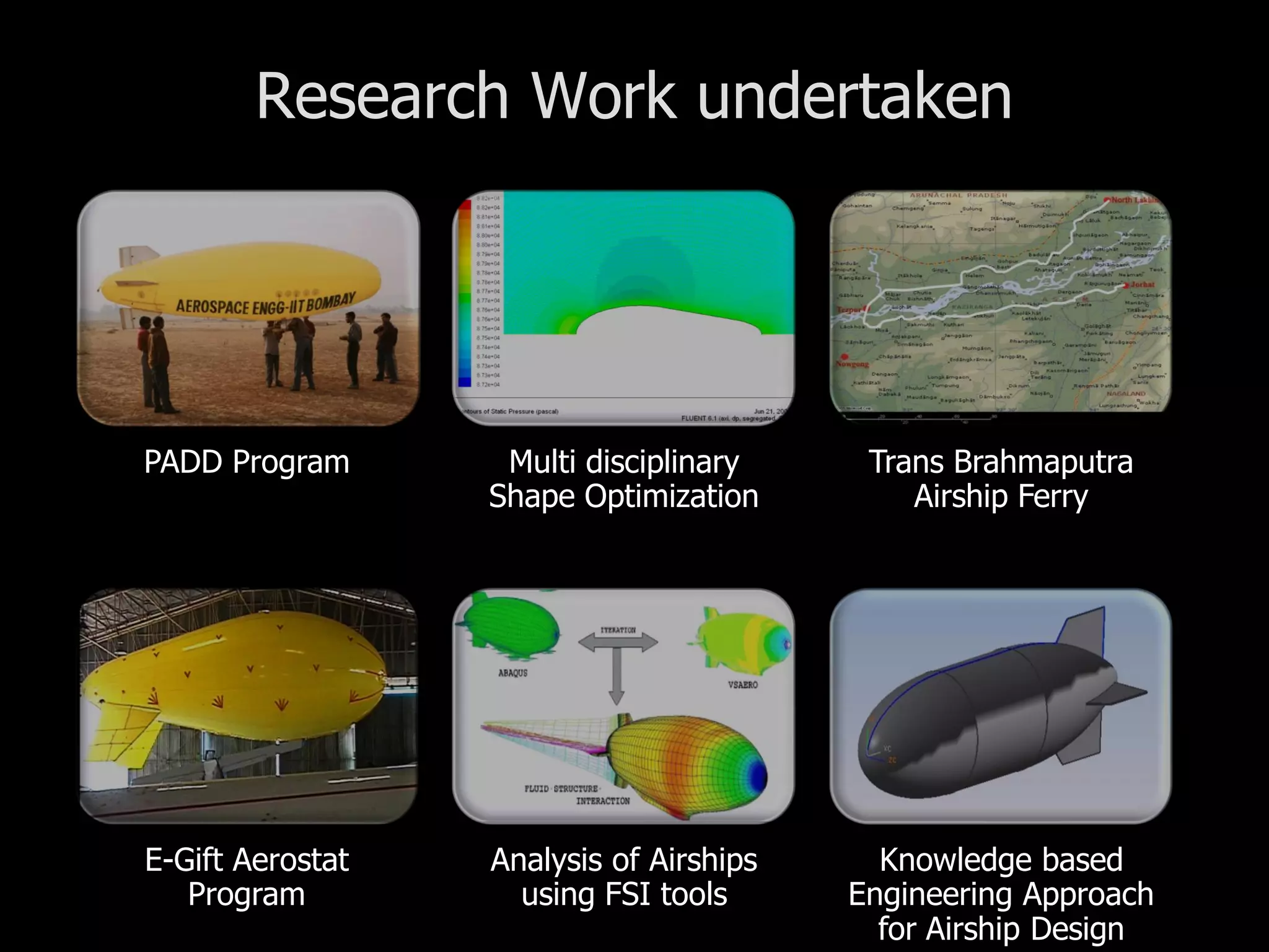
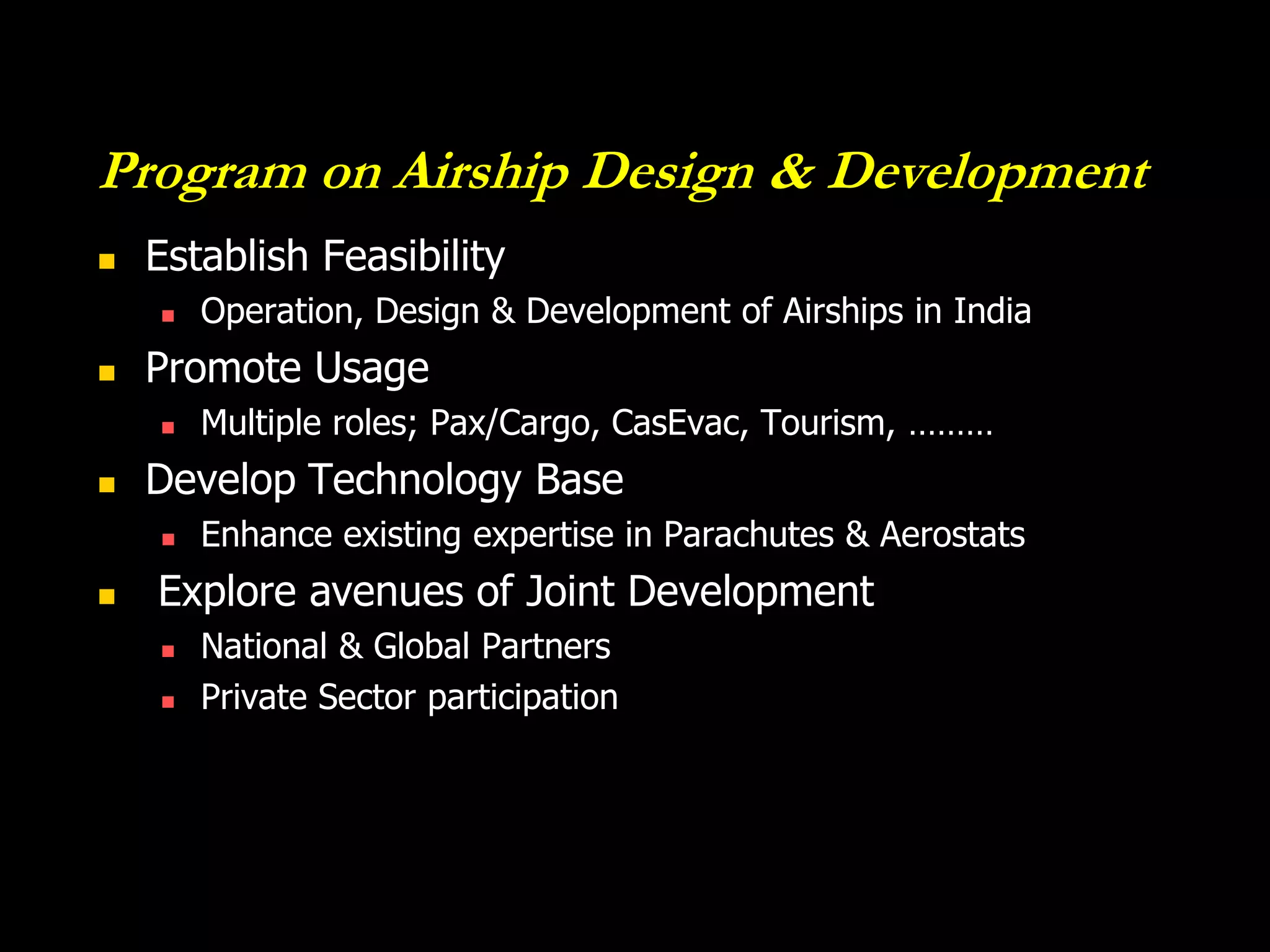
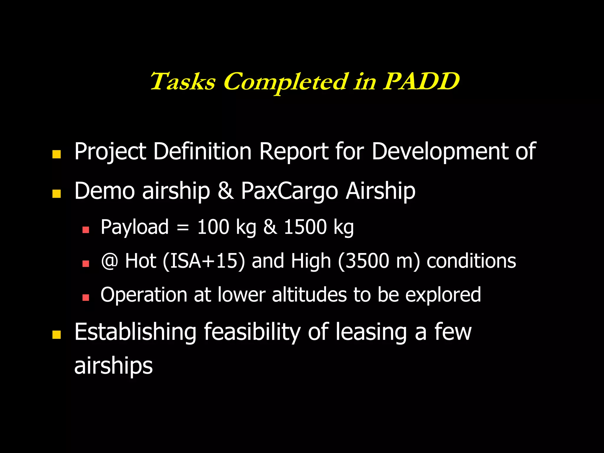
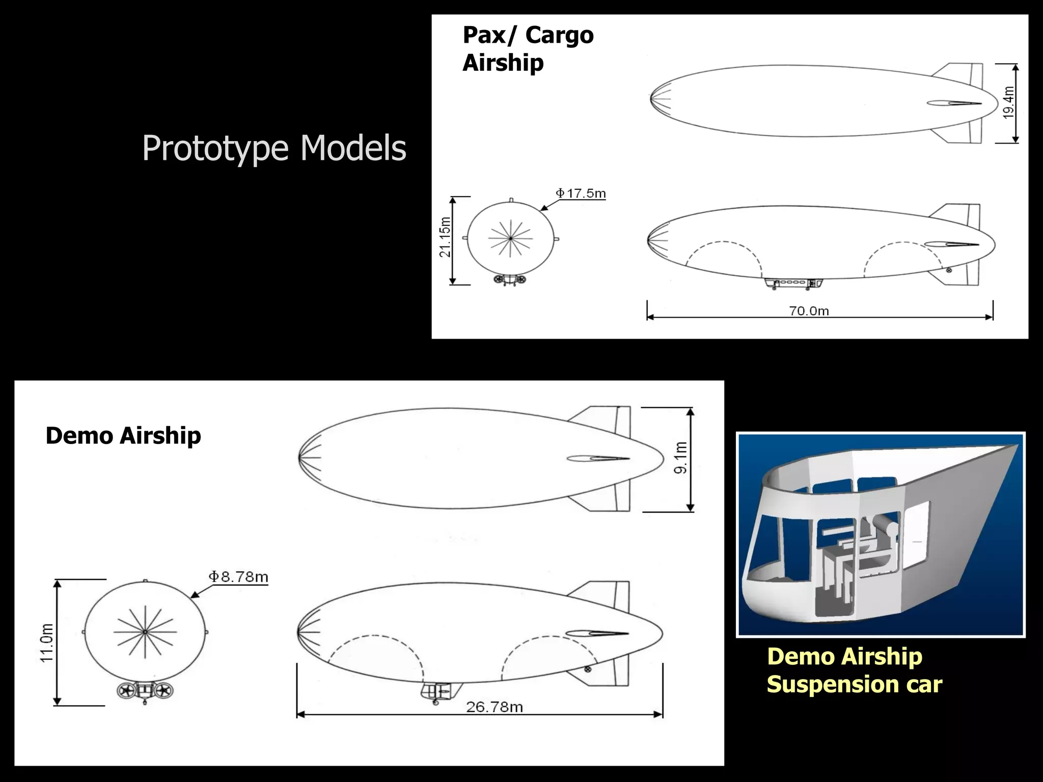
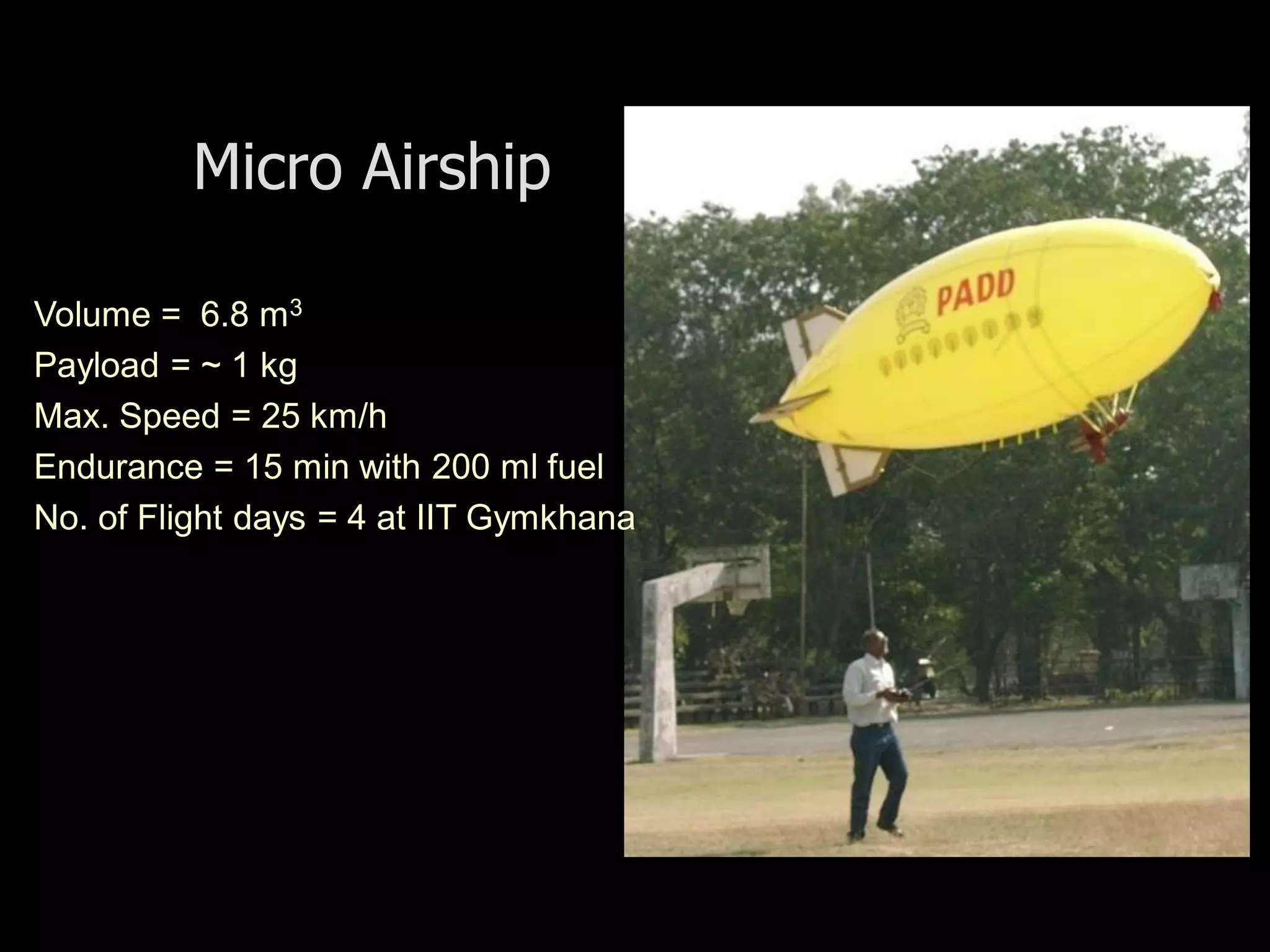
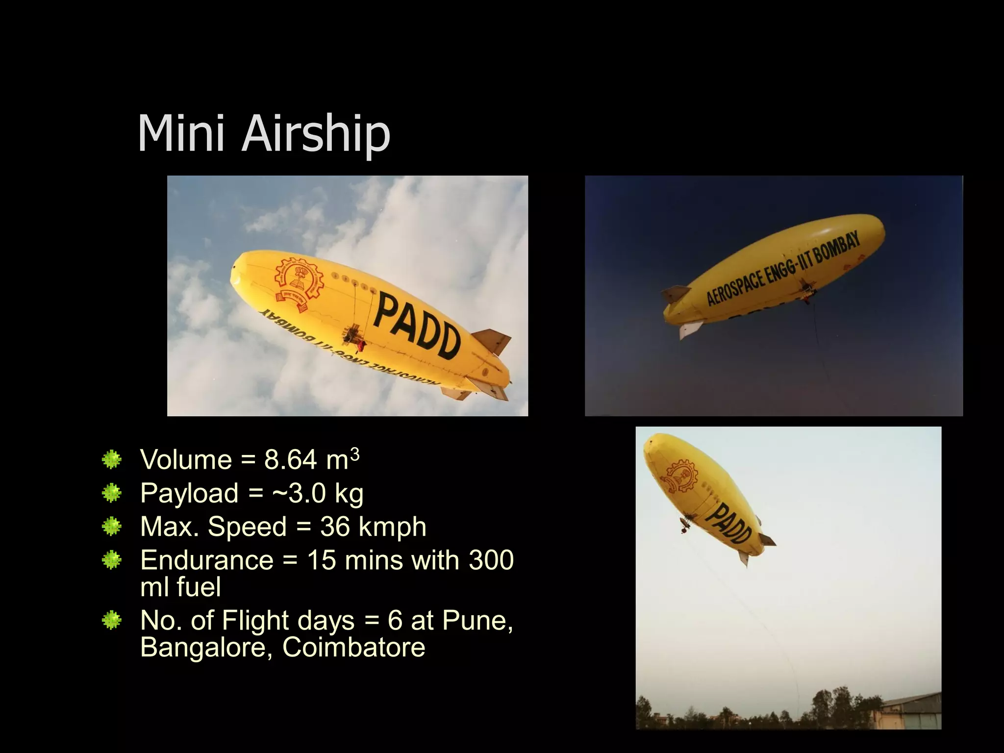
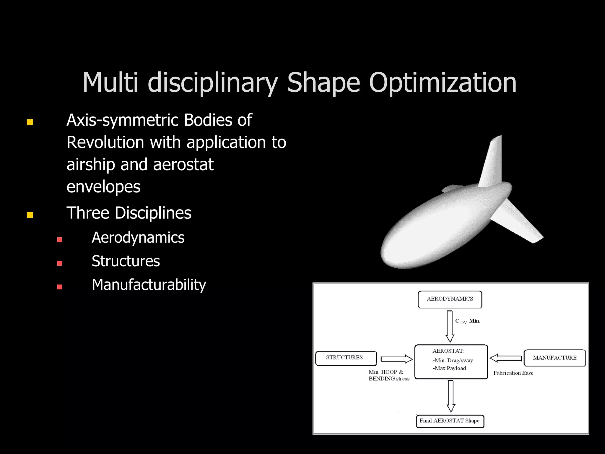
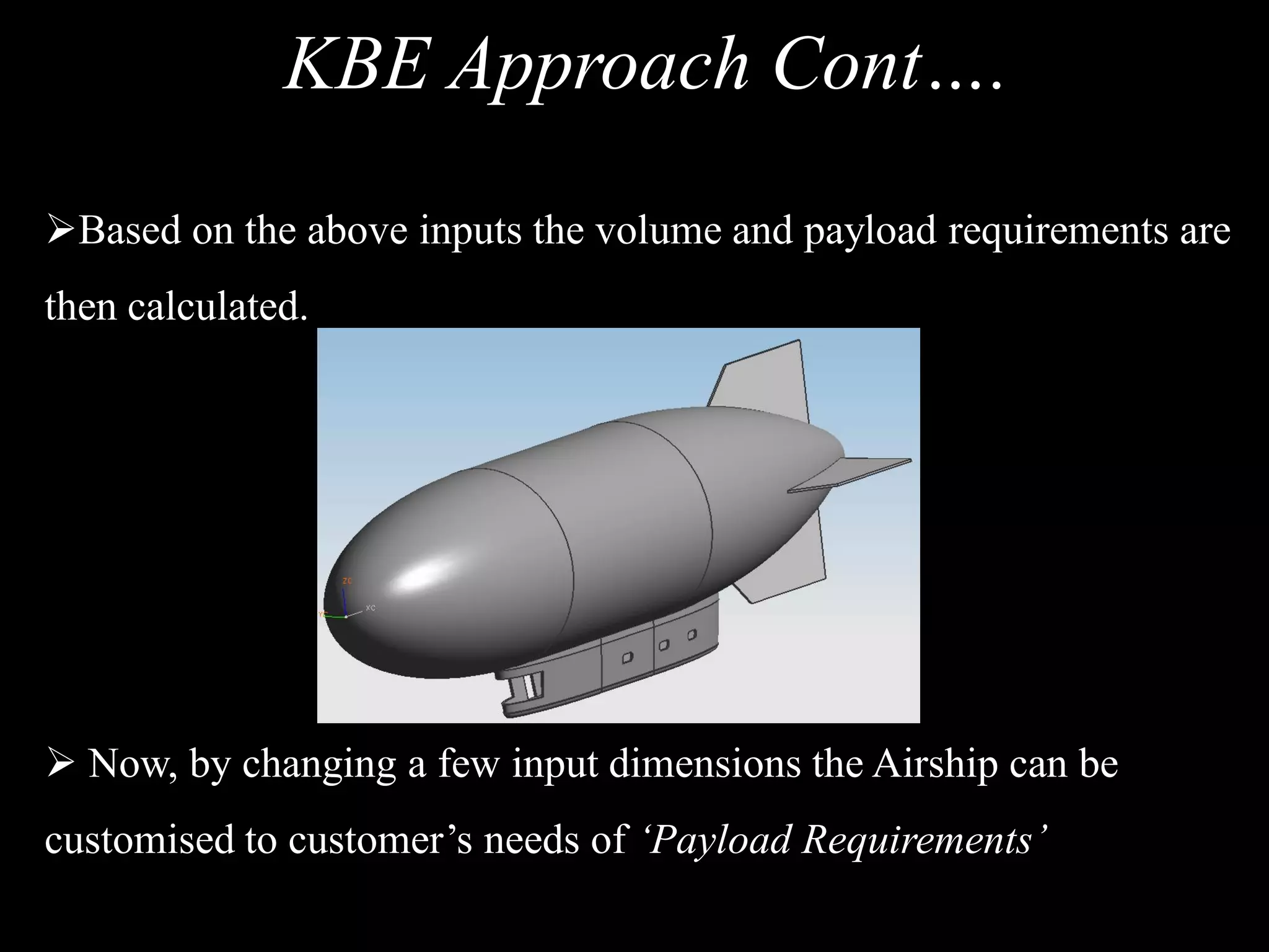
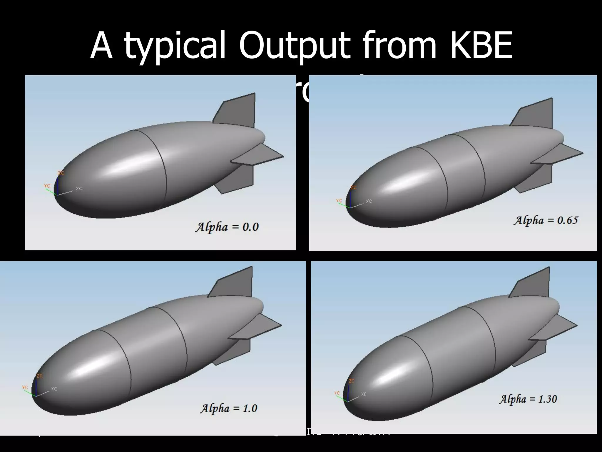
R&D of Lighter – than – air systems
                                Amool A Raina
                                Project Engineer
                     Aerospace Engineering Department
                    Indian Institute of Technology Bombay


April 23rd , 2009             R&D @ LTA IITB
Research Work undertaken


PADD Program       Multi disciplinary     Trans Brahmaputra
                  Shape Optimization         Airship Ferry


E-Gift Aerostat   Analysis of Airships     Knowledge based
   Program          using FSI tools      Engineering Approach
                                           for Airship Design
Initial review and Study Projects
Program on Airship Design & Development

                PADD
Program on Airship Design & Development
   Establish Feasibility
       Operation, Design & Development of Airships in India
   Promote Usage
       Multiple roles; Pax/Cargo, CasEvac, Tourism, ………
   Develop Technology Base
       Enhance existing expertise in Parachutes & Aerostats
   Explore avenues of Joint Development
       National & Global Partners
       Private Sector participation
Tasks Completed in PADD

   Project Definition Report for Development of
   Demo airship & PaxCargo Airship
       Payload = 100 kg & 1500 kg
       @ Hot (ISA+15) and High (3500 m) conditions
       Operation at lower altitudes to be explored
   Establishing feasibility of leasing a few
    airships
Pax/ Cargo
                          Airship


       Prototype Models


Demo Airship


                                       Demo Airship
                                       Suspension car
Design, Fabrication & Testing of Remotely
           Controlled Airships


       As a part of ongoing PADD Project
Micro Airship

Volume = 6.8 m3
Payload = ~ 1 kg
Max. Speed = 25 km/h
Endurance = 15 min with 200 ml fuel
No. of Flight days = 4 at IIT Gymkhana
Mini Airship


Volume = 8.64 m3
Payload = ~3.0 kg
Max. Speed = 36 kmph
Endurance = 15 mins with 300
ml fuel
No. of Flight days = 6 at Pune,
Bangalore, Coimbatore
Shape Optimization of Aerostat
Envelopes
         Sponsored by ADRDE, Agra
Multi disciplinary Shape Optimization
          Axis-symmetric Bodies of
           Revolution with application to
           airship and aerostat
           envelopes
          Three Disciplines
             Aerodynamics
             Structures
             Manufacturability


20th December
Results of Initial studies

                       GNVR

                      Least Drag


                    Least Surface


                  Least Stress


                  Overall Best
                  Profile


20th December
Core projects undertaken and
          completed
E- Gift Aerostat Design Project

         Sponsored by One World South Asia


20th December
2007
Schematic of Aerostat Communication
                              System
                                              Aerostat
   Omni Directional
   Base Antenna

                 10km
                                           50-100m
                                                         Client
                                                         antenna

                        PoE Cable


Router Board                Winch with
                            Power Supply                      LTA
20th December
Envelope Profile
                                                                              Profile
                                 Aerostat Profile with Petal and Fin          Fin Geometry
                                                                              Single Petal
             12.00                                                            Single Petal Bottom
                                                                              Petal Weld Margin


             10.00


              8.00
Radius (m)


              6.00


              4.00


              2.00


              0.00
                  0.00   2.00    4.00              6.00                8.00   10.00           12.00

                                               Length (m)
Tether Profile under wind loading
    120.00


    100.00                                                           15 m/s
                                                                     10 m/s
                                                                     5 m/s
             80.00
Height (m)


             60.00


             40.00


             20.00


              0.00
                  0.00     20.00   40.00      60.00     80.00   100.00    120.00
                                           Blowby (m)
Fin Geometry
4.000


3.500
                                                             NACA 0018 Root
                                                             NACA 0018 Tip
                                                             Fin Elevation
3.000                                                        Spar1
                                                             Spar 2
                                                             Spar 3
                                                             Spar 4
2.500                                                        Spar 5
                                                             Spar 6
                                                             Spar 7
                                                             Spar 8
2.000                                                        Spar 9
                                                             Spar 10
                                                             Spar 11
                                                             Spar 12

1.500


1.000


0.500


0.000
    0.000   0.500   1.000    1.500   2.000   2.500   3.000   3.500            4.000

-0.500
Envelope and Fin Fabrication


20th December
Envelope Fabrication Techniques


20th December   Master Template & Fabrication of Envelope
Fin Fabrication


                       Rib
                       Fabrication


20th December
Field Trials

   May 2007               August 2007
       BATU, Raigarh          GCP, Pune
Trans Brahmaputra Aerial Ferry
                Sponsored by DSIR


20th December
The Problem


       Possible airship ferry between Jorhat to North Lakhimpur reducing a travel
                         of around 300 km by road to just 40 km

20th December
Tether & Winch Propelled Captive-HAB
                                CAPTIVE HAB                   River bank


                                TETHER / CABLES


      River bank                                  MOTORIZED WINCHES

20th December
Knowledge based Engineering Approach
         for Airship Design
Knowledge Based Engineering
            (KBE)
 KBE is defined as engineering on the basis of electronic

knowledge models.

Knowledge models can be imported or stored enabling

engineers to create designs on the basis of the knowledge in such

models

 Highly adaptive to various design problems.

 Makes the design process highly iterative in nature.
KBE Approach for Airship Design
 Specific methodology is developed based on High Level
Primitives (HLP).


In case of an Airship the HLP’s consist of fully parametric
models of the various segments of an airship.
KBE Approach Cont….

Based on the above inputs the volume and payload requirements are
then calculated.


 Now, by changing a few input dimensions the Airship can be
customised to customer’s needs of ‘Payload Requirements’
A typical Output from KBE
                           Approach


17th April 2008            R&D @ LTA IITB - PPT For IITM
Conceptual study of unmanned
     high altitude aerial platforms
• For scientific research by SASE
• Applications
  • Real-time monitoring of avalanche parameters at the
    upper Himalayas
  • Observation of work-in-progress at the tunnel
Design of an aerostat for aerial
        observation at Dhundi
   Mandate
       Conceptual design and sizing of an aerostat
            meeting SASE’s operational requirements
       Generate documents and fabrication plans
            using which the aerostat can be fabricated
            by an industry partner decided by SASE
   Scaled prototype of the system to be fabricated
    and tested through a field trial
       by an industry partner decided by SASE
Analysis of Airships using FSI Tools
     (Project Mentored by me)
Fluid Structure Interaction - FSI
 FSI refers to problem solving using equations which govern the
motion of fluid and structure particles during their interaction.
 Various Methodologies used are:
    FSI Modeling Models
        Fully Coupled Model
        Loosely Coupled Model
       Closely Coupled Mode
    ALE (Arbitrary Lagrangian Eulerian)
    IFEM (Immersed Finite Element Method)
        Fluid domain assumptions
        Solid domain assumptions
        The overlapping domain
    FD (Fictitious Domain) Method
    Fluid and Structure Coupling Mechanisms
Analysis of Airships using FSI Tools
Consists of three Stages:
Stage 1:
   Structural Modeling of Airship Body using FEM
   package called ABAQUS


                                               Stage 2
                                                    Generation of Aerodynamic model
                                                    using VSAERO


 Stage 3
     Coupling of VSAERO and ABAQUS
     models
This presentation showcased my work at IIT
            Bombay carried out by me from 2007-2008


                   If interested, please contact:
                     amoolraina@gmail.com


20th December
2007

L T A Activities@IITB-Amool

  • 1.
    R&D of Lighter– than – air systems Amool A Raina Project Engineer Aerospace Engineering Department Indian Institute of Technology Bombay April 23rd , 2009 R&D @ LTA IITB
  • 2.
    Research Work undertaken PADDProgram Multi disciplinary Trans Brahmaputra Shape Optimization Airship Ferry E-Gift Aerostat Analysis of Airships Knowledge based Program using FSI tools Engineering Approach for Airship Design
  • 3.
    Initial review andStudy Projects
  • 4.
    Program on AirshipDesign & Development PADD
  • 5.
    Program on AirshipDesign & Development  Establish Feasibility  Operation, Design & Development of Airships in India  Promote Usage  Multiple roles; Pax/Cargo, CasEvac, Tourism, ………  Develop Technology Base  Enhance existing expertise in Parachutes & Aerostats  Explore avenues of Joint Development  National & Global Partners  Private Sector participation
  • 6.
    Tasks Completed inPADD  Project Definition Report for Development of  Demo airship & PaxCargo Airship  Payload = 100 kg & 1500 kg  @ Hot (ISA+15) and High (3500 m) conditions  Operation at lower altitudes to be explored  Establishing feasibility of leasing a few airships
  • 7.
    Pax/ Cargo Airship Prototype Models Demo Airship Demo Airship Suspension car
  • 8.
    Design, Fabrication &Testing of Remotely Controlled Airships As a part of ongoing PADD Project
  • 9.
    Micro Airship Volume =6.8 m3 Payload = ~ 1 kg Max. Speed = 25 km/h Endurance = 15 min with 200 ml fuel No. of Flight days = 4 at IIT Gymkhana
  • 10.
    Mini Airship Volume =8.64 m3 Payload = ~3.0 kg Max. Speed = 36 kmph Endurance = 15 mins with 300 ml fuel No. of Flight days = 6 at Pune, Bangalore, Coimbatore
  • 11.
    Shape Optimization ofAerostat Envelopes Sponsored by ADRDE, Agra
  • 12.
    Multi disciplinary ShapeOptimization  Axis-symmetric Bodies of Revolution with application to airship and aerostat envelopes  Three Disciplines  Aerodynamics  Structures  Manufacturability 20th December
  • 13.
    Results of Initialstudies GNVR Least Drag Least Surface Least Stress Overall Best Profile 20th December
  • 14.
  • 15.
    E- Gift AerostatDesign Project Sponsored by One World South Asia 20th December 2007
  • 16.
    Schematic of AerostatCommunication System Aerostat Omni Directional Base Antenna 10km 50-100m Client antenna PoE Cable Router Board Winch with Power Supply LTA 20th December
  • 17.
    Envelope Profile Profile Aerostat Profile with Petal and Fin Fin Geometry Single Petal 12.00 Single Petal Bottom Petal Weld Margin 10.00 8.00 Radius (m) 6.00 4.00 2.00 0.00 0.00 2.00 4.00 6.00 8.00 10.00 12.00 Length (m)
  • 18.
    Tether Profile underwind loading 120.00 100.00 15 m/s 10 m/s 5 m/s 80.00 Height (m) 60.00 40.00 20.00 0.00 0.00 20.00 40.00 60.00 80.00 100.00 120.00 Blowby (m)
  • 19.
    Fin Geometry 4.000 3.500 NACA 0018 Root NACA 0018 Tip Fin Elevation 3.000 Spar1 Spar 2 Spar 3 Spar 4 2.500 Spar 5 Spar 6 Spar 7 Spar 8 2.000 Spar 9 Spar 10 Spar 11 Spar 12 1.500 1.000 0.500 0.000 0.000 0.500 1.000 1.500 2.000 2.500 3.000 3.500 4.000 -0.500
  • 20.
    Envelope and FinFabrication 20th December
  • 21.
    Envelope Fabrication Techniques 20thDecember Master Template & Fabrication of Envelope
  • 22.
    Fin Fabrication Rib Fabrication 20th December
  • 23.
    Field Trials  May 2007  August 2007  BATU, Raigarh  GCP, Pune
  • 24.
    Trans Brahmaputra AerialFerry Sponsored by DSIR 20th December
  • 25.
    The Problem Possible airship ferry between Jorhat to North Lakhimpur reducing a travel of around 300 km by road to just 40 km 20th December
  • 26.
    Tether & WinchPropelled Captive-HAB CAPTIVE HAB River bank TETHER / CABLES River bank MOTORIZED WINCHES 20th December
  • 27.
    Knowledge based EngineeringApproach for Airship Design
  • 28.
    Knowledge Based Engineering (KBE)  KBE is defined as engineering on the basis of electronic knowledge models. Knowledge models can be imported or stored enabling engineers to create designs on the basis of the knowledge in such models  Highly adaptive to various design problems.  Makes the design process highly iterative in nature.
  • 29.
    KBE Approach forAirship Design  Specific methodology is developed based on High Level Primitives (HLP). In case of an Airship the HLP’s consist of fully parametric models of the various segments of an airship.
  • 30.
    KBE Approach Cont…. Basedon the above inputs the volume and payload requirements are then calculated.  Now, by changing a few input dimensions the Airship can be customised to customer’s needs of ‘Payload Requirements’
  • 31.
    A typical Outputfrom KBE Approach 17th April 2008 R&D @ LTA IITB - PPT For IITM
  • 32.
    Conceptual study ofunmanned high altitude aerial platforms • For scientific research by SASE • Applications • Real-time monitoring of avalanche parameters at the upper Himalayas • Observation of work-in-progress at the tunnel
  • 33.
    Design of anaerostat for aerial observation at Dhundi  Mandate  Conceptual design and sizing of an aerostat  meeting SASE’s operational requirements  Generate documents and fabrication plans  using which the aerostat can be fabricated  by an industry partner decided by SASE  Scaled prototype of the system to be fabricated and tested through a field trial  by an industry partner decided by SASE
  • 34.
    Analysis of Airshipsusing FSI Tools (Project Mentored by me)
  • 35.
    Fluid Structure Interaction- FSI  FSI refers to problem solving using equations which govern the motion of fluid and structure particles during their interaction.  Various Methodologies used are:  FSI Modeling Models  Fully Coupled Model  Loosely Coupled Model Closely Coupled Mode  ALE (Arbitrary Lagrangian Eulerian)  IFEM (Immersed Finite Element Method)  Fluid domain assumptions  Solid domain assumptions  The overlapping domain  FD (Fictitious Domain) Method  Fluid and Structure Coupling Mechanisms
  • 36.
    Analysis of Airshipsusing FSI Tools Consists of three Stages: Stage 1: Structural Modeling of Airship Body using FEM package called ABAQUS Stage 2 Generation of Aerodynamic model using VSAERO Stage 3 Coupling of VSAERO and ABAQUS models
  • 37.
    This presentation showcasedmy work at IIT Bombay carried out by me from 2007-2008 If interested, please contact: amoolraina@gmail.com 20th December 2007