(INDIRA) Call Girl Aurangabad Call Now 8617697112 Aurangabad Escorts 24x7
CV6314_Lect_1_excavation_4slides_2012.pdf
1. NANYANG TECHNOLOGICAL UNIVERSITY
SC OO O C O G G
SCHOOL OF CIVIL AND ENVRONMENTAL ENGINEERING
CV6314
CV6314
EXCAVATION & EARTH RETAINING SYSTEMS
Part 2 -- Braced Excavation
By
By
A/P Anthony Goh
ctcgoh@ntu.edu.sg
6790-5271
CV6314 - Overview 1
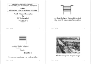
A robust design is the most important
t t d f l ti
step towards a successful excavation.
CV6314 - Overview 2
A poor design brings…
Headache
Headache
Trouble
Disaster !!!
The end result is cost over-run and time delay!
CV6314 - Overview 3
Potential consequence of a poor design!
CV6314 - Overview 4
2. Comparison of Computed & Measured Wall Deflections
105
Measured
Computed using Method A
90
95
100
80
85
90
Level
(m)
Level
(m)
70
75
80
Reduced
L
Reduced
L
60
65
Level 10
325 mm
R
R
50
55
CV6314 - Overview 5
0 50 100 150 200 250 300 350 400
Formation = 118 mm
Final = 145 mm Wall Deflection (mm)
Poor initial design resulted in many rounds
Poor initial design resulted in many rounds
of redesign and resetting of new goal posts
450
500
350
400
450
m
m
)
3rd Goal Post
250
300
f
le
c
t
io
n
(
m
2nd Goal Post
100
150
200
W
a
ll
D
e
f
1st Goal Post
1st Goal Post
0
50
100
CV6314 - Overview 6
1/4/04 1/19/04 2/3/04 2/18/04 3/4/04 3/19/04 4/3/04 4/18/04
Here is a quote from a local “authority” figure:
“At least half of the FE analyses
reviewed in Singapore contained
reviewed in Singapore contained
major, fundamental errors.”
-- UGS2005
No wonder why we have so many
failures and near failures in excavation
related incidents in recent years!
CV6314 - Overview 7
Lectures on Braced Excavation
™ O i
™ Overview
™ Basal heave
™ T bili
™ Toe stability
™ Strut forces
™ Bending moment
™ Wall deflection and ground settlement
™ Numerical modeling
™ Mohr-Coulomb soil model
™ Jet grouting
™ Evaluation of material properties
™ Instrumentation
™ Observational method
CV6314 - Overview 8
™ Case Studies
3. Overview of
Braced Excavation
Braced Excavation
• Types of walls
M th d f ti
• Methods of excavation
• Modes of failure
odes o a u e
CV6314 - Overview 9
Types of Retaining Walls for Excavation
Cantilever Wall Anchored or Braced Wall
Cantilever Wall
Propped Wall
CV6314 - Overview 10
Plane strain analysis
Braced Wall
11
Wall Types of Deep Excavations
¾ Diaphragm Wall
¾ Sheetpile Wall
¾ Bored Pile Wall
¾ Bored Pile Wall
¾ Soldier Pile Wall
¾ DCM or Grout
Mixed Pile Wall
Mixed Pile Wall
CV6314 - Overview 12
4. Braced Excavation with Diaphragm Wall
p g
wall
struts
walers
walers struts
kingposts
wall
wall
CV6314 - Overview 13
Strut (can be reused)
Waler
14
Construction of Diaphragm Wall
CV6314 - Overview 15 CV6314 - Overview 16
5. CV6314 - Overview 17
Concrete
Diaphragm Wall
Stop-ends & water-proofs
CV6314 - Overview 18
Integrated Resort at Marina Bay
CV6314 - Overview 19
Ring Beam System
Central at
Clarke Quay
y
in Singapore
CV6314 - Overview 20
7. 18.5m Cantilever CBP wall at NUS
Contiguous
Contiguous
Bored Pile Wall
CV6314 - Overview 25
Construction of Secant Bored Pile Wall
CV6314 - Overview 26
Braced Excavation with Soldier Pile Wall
CV6314 - Overview 27 28
8. Construction of DCM or Grout Mixed Pile Wall
CV6314 - Overview 29
Properties of DCM or Grout Mixed Pile Wall
p
Soil Amount of q
Soil
Type
Amount of
Cement
(kg/m3)
qu
(kPa)
(kg/m )
Peaty
Clay
250 - 500 400 - 700
y
Sandy
Clay
200 - 350 700 -1000
E 35 MPa
y
Marine
Clay
100 - 250 200 - 700
E50 ~35 MPa
CV6314 - Overview 30
Grout Mixed Pile Wall
CV6314 - Overview 31
wall
struts
wall
walers
walers t t
kingposts
walers struts
Conventional
wall
Bottom-Up
Excavation
Method
CV6314 - Overview 32
9. walers
t t
strut
CV4352 33
Top Down
Top-Down
Excavation
CV6314 - Overview 34
Top-Down Excavation at Boon Keng Station
Top Down Excavation at Boon Keng Station
CV6314 - Overview 35
125m
P50
0
m
99 m
P19
Nicoll Highway Extension
Avenue
50
4
5
Legend:
Inclinometers
Water standpipes
Strain gauges
Total earth pressure cells
P3
6
5
m
4
5
59
m
5
Raffles
A
N
Diaphragm walls
Composite sheet pile and soldier pile wall
184 m
45
4
5
Esplanade car park - top down construction
36
10. 37
Up-Down Construction Method
CV6314 - Overview 38
Island Method of Excavation
CV6314 - Overview 39
Zoned excavation
1. Excavate Zone A 2. Install struts in Zone A
3. Excavate Zone B 4. Install struts in Zone B
Repeat 1 to 4 for next stage of excavation
wall
wall
Zone A Zone B
Zone B
Plan view of
excavation
40
excavation
11. Zoned excavation
1. Excavate shaded zones
2. Cast slabs or install struts
3. Excavate unshaded zones and cast slab/install struts
4. Repeat 1 to 3 for the next excavation level
wall
wall
Plan view of
excavation
41
excavation
Underwater Excavation
t
water
42
Underwater Excavation
water
water
43
Under Water
E ti
Excavation
at
Marina South
CV6314 - Overview 44
12. reclaimed land
reclaimed land
CV4352 45
≈ 15 m excavation depth. Basal heave critical.
CV4352 46
Marina Bay MRT
Denman et al.
(1987)
CV4352 47
(1987)
CV4352 48
13. CV4352 49 CV4352 50
Major Design Considerations in Deep Excavations
ajo es g Co s de at o s eep ca at o s
Total collapse
¾ O ll t bilit Excessive movements
¾ Wall deflections
¾ G d l
¾ Overall stability
¾ Basal heave
¾ Uplift or blow out failure ¾ Ground settlement
¾ Effect on adjacent
structures
¾ Uplift or blow-out failure
¾ Toe stability
¾ Strutting system failure
CV6314 - Overview 51
structures
¾ Strutting system failure
Overall
Stability
CV6314 - Overview 52
15. Basal Heave Failure due to Stockpiling
Basal Heave Failure due to Stockpiling
Excessive Surcharge
Excessive Surcharge
q = 20 kPa
CV6314 - Overview 57
Basal Heave Failure due to Stockpiling
Basal Heave Failure due to Stockpiling
Stockpile
CV6314 - Overview 58
Courtesy of Dr Lim PC
Basal Heave Stability
Basal Heave Stability
Wall Rotation
CV6314 - Overview 59
Basal Heave Stability
Basal Heave Stability
Wall Raking
Wall Raking
CV6314 - Overview 60
16. Basal Heave Stability
Lifting of King Posts
Lifting of King Posts
Jet Grout Slab
CV6314 - Overview 61
Lifting of Kingpost due to Bottom Heave
Lifting of Kingpost due to Bottom Heave
CV6314 - Overview 62
Basal Heave Stability
Basal Heave Stability
Not all basal heave instability
Not all basal heave instability
lead to catastrophic failures
Formation
Formation
Level
CV6314 - Overview 63
Piping
Piping
&
Loss of Fines
Loss of Fines
CV6314 - Overview 64
17. Uplift Instability or Blowout Failure
Fill
E
UMC
F2
F2
LMC
E / F2
S d
Sand
1 What is the permeability of the sand?
CV6314 - Overview 65
1. What is the permeability of the sand?
2. Is there a free supply of water?
Bottom Heave due to Uplift
p
at End of Excavation
CV6314 - Overview 66
Blowout Failure γT B d + 2 Ca d
Fs = ------------------------
Fs = ------------------------
γw h B
B
γT
CV6314 - Overview 67
Toe Kick-out Stability
M
La
L
Pa
Pp
La
Lp
CV6314 - Overview 68
19. Buildings on Shallow Foundations
Race Course Road
CV6314 - Overview 73
Race Course Road
Buildings on Shallow Foundations
Buildings on Shallow Foundations
CV6314 - Overview 74
Post-excavation Settlement
Maximum Wall Deflection Vs. Building Settlement (I312 Vs. L386, C706)
0 14
0.15
C
Post excavation Settlement
0.12
0.13
0.14 C
ment
(m)
0.09
0.10
0.11
EXCAVATION
lding
Settlem
0.06
0.07
0.08
EXCAVATION
Buil
0.03
0.04
0.05 B
0.00
0.01
0.02
A
CV6314 - Overview 75
Horizontal Movement (m)
0.00 0.01 0.02 0.03 0.04 0.05 0.06 0.07 0.08 0.09 0.10 0.11 0.12 0.13 0.14 0.15
Building on Mixed Foundations
(Shi l t l 2003)
(Shirlaw et al., 2003)
Sunday
New
kindergarten
y
School
kindergarten
section Old
Church,
wrapped in
wrapped in
extension
CV6314 - Overview 76
20. Building on Mixed Foundations
g
CV6314 - Overview 77
APG Building
244 242/241 240
245
APG
Building
Pile Raft
245 Pile
Foundation
Raft
Foundation
246 243
Markers on piles Markers on raft
Markers on piles Markers on raft
LB-242 – 8 mm LB-240 – 38 mm
LB-245 – 6 mm LB-241 – 42 mm
78
LB-246 – 7 mm
79 CV4352 80
21. BCA
81 82
car park
Possible causes of failure
♦ Insufficient penetration of
contiguous bored pile wall
♦ Inadequate strutting
♦ Over-excavation
83 84
22. Lowering of Ground Water Table
Well point
Well point
Causes:
¾ Pumping
¾ Wall leakage
Sand
Marine
Clay
Old
Alluvium
Alluvium
Lowering of ground water table will increase the effective
stress in soft clay and result in consolidation settlement
CV6314 - Overview 85
stress in soft clay and result in consolidation settlement.
Effect of Lowering of Groundwater Table
g
CV6314 - Overview 86
Sarawak
3 storey
shophouses
12 m excavation,
grdwater lowered
g
5 m
87
Gue (2004)
88
24. E i S h
Excessive Surcharge
q = 20 kPa
CV6314 - Overview 93
Sequence of Construction
q
As-Built Design
g
CV6314 - Overview 94
ARCHING
shear
When the movement of the wall is different from the tilting required to
When the movement of the wall is different from the tilting required to
establish the active or passive states, both the magnitude and the
distribution of the earth pressure are changed.
If a section of the wall deflects outwards more than the neighbouring
If a section of the wall deflects outwards more than the neighbouring
sections, the soil adjacent to it will tend to follow.
Horizontal shear develops along the boundaries of this section, and this
t i it t f i t f th l t l l d it i t th dj i i
CV4352 95
restrains it, transferring part of the lateral load it carries to the adjoining
soil.
The result is a redistribution of pressure by shear,
p y
commonly called arching, and an irregular pressure
distribution. One example where the conditions for arching
t i i h d h t il ll R di t ib ti f
are present is in anchored sheetpile walls. Redistributions of
earth pressure result in lower bending moments (Rowe
1952)
1952).
CV4352 96
25. Prop or
Prop or
anchor
Lateral stress reduction
due to arching when
due to arching when
prop is rigid
σ’h=Koσ’v
σ’h=Kaσ’v (active)
CV4352 97
σ h Kaσ v (active)
Prop or Rowe (1952)
Prop or
anchor
Rowe (1952)
Actual stress
Flexible wall with deflection at
excavation level significantly
greater than at the toe
distribution greater than at the toe,
resulting in the raising of the
centroid of the passive stress
di t ib ti Thi lt d i
Full
distribution. This resulted in
smaller anchor loads and
bending moments than those
Full
passive given by the factored limit
equilibrium calculation
σ’h=Kaσ’v (active)
CV4352 98
σ h Kaσ v (active)
Microsoft
Microsoft
werPoint Presentat
CV4352 99
C580 CV4352 100
26. 1,600-seat concert hall
2,000-seat theatre
No floor slabs on ground and
fi t b t l l
~180 m
first basement levels
10 m height clearance
CV4352 101 CV4352 102
Reclaimed land
south
south
CV4352 103
ARTS
CENTRE
180 m
CENTRE
CV4352 104
27. Sheetpile wall
16 m wide concrete slab
diaphragm wall
(1m thick)
CV4352 105
1 m thick
Buttress walls
Buttress walls
at 8-10 m
intervals
CV4352 106
16 m wide
6 m
concrete slab
S il t b
Soil pressure to be
transferred onto the slab
and then down to the 1 m
and then down to the 1 m
diameter bored piles
CV4352 107
Maximum allowable wall deflection = 75 mm
Maximum allowable wall deflection = 75 mm
Required use of 2 m thick jet grout slab
CV4352 108
28. CV4352 109 CV4352 110
CV4352 111
To minimize
movements of the
installed piles, strict
t l
control was
exercised to keep the
difference in the
difference in the
ground level not to
exceed 1 m during
g
excavation.
CV4352 112