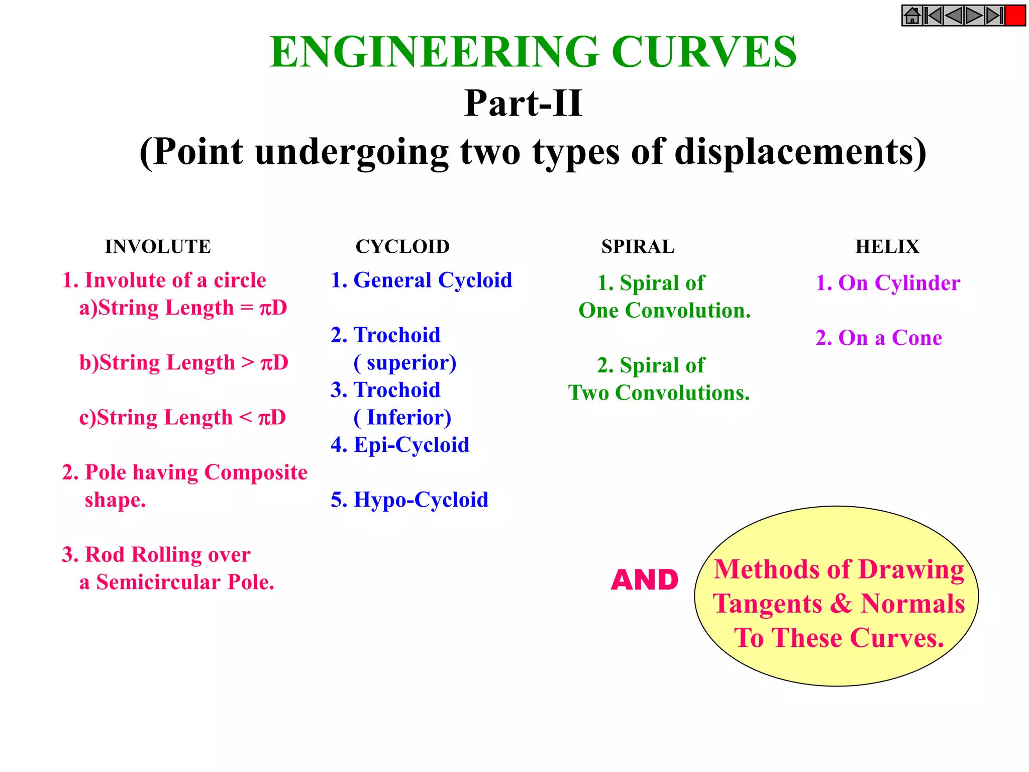
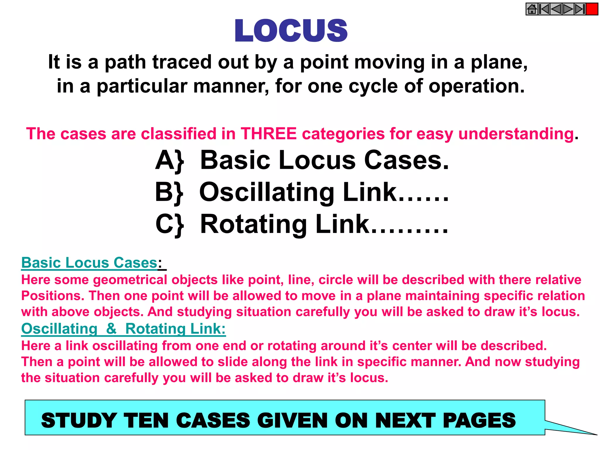
SlideShare a Scribd company logo
INVOLUTE CYCLOID SPIRAL HELIX
ENGINEERING CURVES
Part-II
(Point undergoing two types of displacements)
1. Involute of a circle
a)String Length = D
b)String Length > D
c)String Length < D
2. Pole having Composite
shape.
3. Rod Rolling over
a Semicircular Pole.
1. General Cycloid
2. Trochoid
( superior)
3. Trochoid
( Inferior)
4. Epi-Cycloid
5. Hypo-Cycloid
1. Spiral of
One Convolution.
2. Spiral of
Two Convolutions.
1. On Cylinder
2. On a Cone
Methods of Drawing
Tangents & Normals
To These Curves.
AND
CYCLOID:
IT IS A LOCUS OF A POINT ON THE
PERIPHERY OF A CIRCLE WHICH
ROLLS ON A STRAIGHT LINE PATH.
INVOLUTE:
IT IS A LOCUS OF A FREE END OF A STRING
WHEN IT IS WOUND ROUND A CIRCULAR POLE
SPIRAL:
IT IS A CURVE GENERATED BY A POINT
WHICH REVOLVES AROUND A FIXED POINT
AND AT THE SAME MOVES TOWARDS IT.
HELIX:
IT IS A CURVE GENERATED BY A POINT WHICH
MOVES AROUND THE SURFACE OF A RIGHT CIRCULAR
CYLINDER / CONE AND AT THE SAME TIME ADVANCES IN AXIAL DIRECTION
AT A SPEED BEARING A CONSTANT RATIO TO THE SPPED OF ROTATION.
( for problems refer topic Development of surfaces)
DEFINITIONS
SUPERIORTROCHOID:
IF THE POINT IN THE DEFINATION
OF CYCLOID IS OUTSIDE THE CIRCLE
INFERIOR TROCHOID.:
IF IT IS INSIDE THE CIRCLE
EPI-CYCLOID
IF THE CIRCLE IS ROLLING ON
ANOTHER CIRCLE FROM OUTSIDE
HYPO-CYCLOID.
IF THE CIRCLE IS ROLLING FROM
INSIDE THE OTHER CIRCLE,
INVOLUTE OF A CIRCLE
Problem no 17: Draw Involute of a circle.
String length is equal to the circumference of circle.
1 2 3 4 5 6 7 8
P
P8
1
2
3
4
5
6
7
8
P3
P4
4 to p
P5
P7
P6
P2
P1

D
A
Solution Steps:
1) Point or end P of string AP is
exactly D distance away from A.
Means if this string is wound round
the circle, it will completely cover
given circle. B will meet A after
winding.
2) Divide D (AP) distance into 8
number of equal parts.
3) Divide circle also into 8 number
of equal parts.
4) Name after A, 1, 2, 3, 4, etc. up
to 8 on D line AP as well as on
circle (in anticlockwise direction).
5) To radius C-1, C-2, C-3 up to C-8
draw tangents (from 1,2,3,4,etc to
circle).
6) Take distance 1 to P in compass
and mark it on tangent from point 1
on circle (means one division less
than distance AP).
7) Name this point P1
8) Take 2-B distance in compass
and mark it on the tangent from
point 2. Name it point P2.
9) Similarly take 3 to P, 4 to P, 5 to
P up to 7 to P distance in compass
and mark on respective tangents
and locate P3, P4, P5 up to P8 (i.e.
A) points and join them in smooth
curve it is an INVOLUTE of a given
circle.
INVOLUTE OFA CIRCLE
String length MORE than D
1 2 3 4 5 6 7 8
P
1
2
3
4
5
6
7
8
P3
P4
4 to p
P5
P7
P6
P2
P1
165 mm
(more than D)
D
p8
Solution Steps:
In this case string length is more
than  D.
But remember!
Whatever may be the length of
string, mark  D distance
horizontal i.e.along the string
and divide it in 8 number of
equal parts, and not any other
distance. Rest all steps are same
as previous INVOLUTE. Draw
the curve completely.
Problem 18: Draw Involute of a circle.
String length is MORE than the circumference of circle.
1 2 3 4 5 6 7 8
P
1
2
3
4
5
6
7
8
P3
P4
4 to p
P5
P7
P6
P2
P1
150 mm
(Less than D)
D
INVOLUTE OFA CIRCLE
String length LESS than D
Problem 19: Draw Involute of a circle.
String length is LESS than the circumference of circle.
Solution Steps:
In this case string length is Less
than  D.
But remember!
Whatever may be the length of
string, mark  D distance
horizontal i.e.along the string
and divide it in 8 number of
equal parts, and not any other
distance. Rest all steps are same
as previous INVOLUTE. Draw
the curve completely.
1
2
3
4
5
6
1 2 3 4 5 6
A
P
D/2
P1
1
to
P
P2
P3
3 to P
P4
P
P5
P6
INVOLUTE
OF
COMPOSIT SHAPED POLE
PROBLEM 20 : A POLE IS OF A SHAPE OF HALF HEXABON AND SEMICIRCLE.
ASTRING IS TO BE WOUND HAVING LENGTH EQUAL TO THE POLE PERIMETER
DRAW PATH OF FREE END P OF STRING WHEN WOUND COMPLETELY.
(Take hex 30 mm sides and semicircle of 60 mm diameter.)
SOLUTION STEPS:
Draw pole shape as per
dimensions.
Divide semicircle in 4
parts and name those
along with corners of
hexagon.
Calculate perimeter
length.
Show it as string AP.
On this line mark 30mm
from A
Mark and name it 1
Mark D/2 distance on it
from 1
And dividing it in 4 parts
name 2,3,4,5.
Mark point 6 on line 30
mm from 5
Now draw tangents from
all points of pole
and proper lengths as
done in all previous
involute’s problems and
complete the curve.
1
2
3
4
D
1
2
3
4
A
B
A1
B1
A2 B2
A3
B3
A4
B4
PROBLEM 21 : Rod AB 85 mm long rolls
over a semicircular pole without slipping
from it’s initially vertical position till it
becomes up-side-down vertical.
Draw locus of both ends A & B.
Solution Steps?
If you have studied previous problems
properly, you can surely solve this also.
Simply remember that this being a rod,
it will roll over the surface of pole.
Means when one end is approaching,
other end will move away from poll.
OBSERVE ILLUSTRATION CAREFULLY!
P
C1 C2 C3 C4 C5 C6 C7 C8 C9 C10 C11 C12
p1
p2
p3
p4
p5
p6
p7
p8
D
CYCLOID
PROBLEM 22: DRAW LOCUS OF A POINT ON THE PERIPHERY OF A CIRCLE
WHICH ROLLS ON STRAIGHT LINE PATH. Take Circle diameter as 50 mm
Solution Steps:
1) From center C draw a horizontal line equal to D distance.
2) Divide D distance into 12 number of equal parts and name them C1, C2, C3__ etc.
3) Divide the circle also into 12 number of equal parts and in clock wise direction, after P name 1, 2, 3 up to 12.
4) From all these points on circle draw horizontal lines. (parallel to locus of C)
5) With a fixed distance C-P in compass, C1 as center, mark a point on horizontal line from 1. Name it P.
6) Repeat this procedure from C2, C3, C4 upto C12 as centers. Mark points P2, P3, P4, P5 up to P8 on the
horizontal lines drawn from 1,2, 3, 4, 5, 6, 7 respectively.
7) Join all these points by curve. It is Cycloid.
p9
p10
p11
p12
1
2
3
5
4
6
7
8
9
10
11
12
C1 C2 C3 C4 C5 C6 C7 C8
p1
p2
p3
p4
p5
p6
p7
p8
1
2
3
4
5
6
7
C
D
SUPERIOR TROCHOID
P
PROBLEM 23: DRAW LOCUS OF A POINT , 5 MM AWAY FROM THE PERIPHERY OF A
CIRCLE WHICH ROLLS ON STRAIGHT LINE PATH. Take Circle diameter as 50 mm
Solution Steps:
1) Draw circle of given diameter and draw a horizontal line from it’s center C of length  D and divide it
in 8 number of equal parts and name them C1, C2, C3, up to C8.
2) Draw circle by CP radius, as in this case CP is larger than radius of circle.
3) Now repeat steps as per the previous problem of cycloid, by dividing this new circle into 8 number of
equal parts and drawing lines from all these points parallel to locus of C and taking CP radius wit
different positions of C as centers, cut these lines and get different positions of P and join
4) This curve is called Superior Trochoid.
P
C1 C2 C3 C4 C5 C6 C7 C8
p1
p2
p
3
p4
p5
p6
p7
p8
1
2
3
4
5
6
7
C
D
INFERIOR TROCHOID
PROBLEM 24: DRAW LOCUS OF A POINT , 5 MM INSIDE THE PERIPHERY OF A
CIRCLE WHICH ROLLS ON STRAIGHT LINE PATH. Take Circle diameter as 50 mm
Solution Steps:
1) Draw circle of given diameter and draw a horizontal line from it’s center C of length  D and divide it
in 8 number of equal parts and name them C1, C2, C3, up to C8.
2) Draw circle by CP radius, as in this case CP is SHORTER than radius of circle.
3) Now repeat steps as per the previous problem of cycloid, by dividing this new circle into 8 number
of equal parts and drawing lines from all these points parallel to locus of C and taking CP radius
with different positions of C as centers, cut these lines and get different positions of P and join
those in curvature.
4) This curve is called Inferior Trochoid.
C2
EPI CYCLOID :
P
O
r = CP
r
R
3600
=
1
2
3
4 5
6
7
Generating/
Rolling Circle
Directing Circle
PROBLEM 25: DRAW LOCUS OF A POINT ON THE PERIPHERY OF A CIRCLE
WHICH ROLLS ON A CURVED PATH. Take diameter of rolling Circle 50 mm
And radius of directing circle i.e. curved path, 75 mm.
Solution Steps:
1) When smaller circle will roll on
larger circle for one revolution it will
cover  D distance on arc and it will
be decided by included arc angle .
2) Calculate  by formula  = (r/R) x
3600.
3) Construct angle  with radius OC
and draw an arc by taking O as center
OC as radius and form sector of angle
.
4) Divide this sector into 8 number of
equal angular parts. And from C
onward name them C1, C2, C3 up to
C8.
5) Divide smaller circle (Generating
circle) also in 8 number of equal parts.
And next to P in clockwise direction
name those 1, 2, 3, up to 8.
6) With O as center, O-1 as radius
draw an arc in the sector. Take O-2, O-
3, O-4, O-5 up to O-8 distances with
center O, draw all concentric arcs in
sector. Take fixed distance C-P in
compass, C1 center, cut arc of 1 at P1.
Repeat procedure and locate P2, P3,
P4, P5 unto P8 (as in cycloid) and join
them by smooth curve. This is EPI –
CYCLOID.
O
P
OP=Radius of directing circle=75mm
C
PC=Radius of generating circle=25mm
θ
θ=r/R X360º= 25/75 X360º=120º
1
2
3
4
5
6
7
8 9 10
11
12
1’
2’
3’
4’
5’
6’
7’
8’
9’
10’
11’
12’
c1
c2
c3
c4
c5
c6
c7
c8
c9 c10
c11
c12
HYPO CYCLOID
P1
P2
P3
P4
P5
P6 P7
P8
P
1
2
3
6
5
7
4
O
OC = R ( Radius of Directing Circle)
CP = r (Radius of Generating Circle)
r
R
3600
=
PROBLEM 26: DRAW LOCUS OF A POINT ON THE PERIPHERY OF A CIRCLE
WHICH ROLLS FROM THE INSIDE OF A CURVED PATH. Take diameter of
rolling circle 50 mm and radius of directing circle (curved path) 75 mm.
Solution Steps:
1) Smaller circle is rolling
here, inside the larger
circle. It has to rotate
anticlockwise to move
ahead.
2) Same steps should be
taken as in case of EPI –
CYCLOID. Only change is
in numbering direction of
8 number of equal parts
on the smaller circle.
3) From next to P in
anticlockwise direction,
name 1,2,3,4,5,6,7,8.
4) Further all steps are
that of epi – cycloid. This
is called
HYPO – CYCLOID.
O
P
OP=Radius of directing circle=75mm
C
PC=Radius of generating circle=25mm
θ
θ=r/R X360º= 25/75 X360º=120º
1
2
3
4
5
6
7
8 9 10
11
12
c2
c1
c3
c4
c5
c6
c7
c8
c9 c10
c11
c12
1’
2’
3’
4’
5’
6’
7’
8’
9’
10’
11’
12’
7 6 5 4 3 2 1
P
1
2
3
4
5
6
7
P2
P6
P1
P3
P5
P7
P4 O
SPIRAL
Problem 27: Draw a spiral of one convolution. Take distance PO 40 mm.
Solution Steps
1. With PO radius draw a circle
and divide it in EIGHT parts.
Name those 1,2,3,4, etc. up to 8
2 .Similarly divided line PO also in
EIGHT parts and name those
1,2,3,-- as shown.
3. Take o-1 distance from op line
and draw an arc up to O1 radius
vector. Name the point P1
4. Similarly mark points P2, P3, P4
up to P8
And join those in a smooth curve.
It is a SPIRAL of one convolution.
IMPORTANT APPROACH FOR CONSTRUCTION!
FIND TOTAL ANGULAR AND TOTAL LINEAR DISPLACEMENT
AND DIVIDE BOTH IN TO SAME NUMBER OF EQUAL PARTS.
16 13 10 8 7 6 5 4 3 2 1 P
1,9
2,10
3,11
4,12
5,13
6,14
7,15
8,16
P1
P2
P3
P4
P5
P6
P7
P8
P9
P10
P11
P12
P13 P14
P15
SPIRAL
of
two convolutions
Problem 28
Point P is 80 mm from point O. It starts moving towards O and reaches it in two
revolutions around.it Draw locus of point P (To draw a Spiral of TWO convolutions).
IMPORTANT APPROACH FOR CONSTRUCTION!
FIND TOTAL ANGULAR AND TOTAL LINEAR DISPLACEMENT
AND DIVIDE BOTH IN TO SAME NUMBER OF EQUAL PARTS.
SOLUTION STEPS:
Total angular displacement here
is two revolutions And
Total Linear displacement here
is distance PO.
Just divide both in same parts i.e.
Circle in EIGHT parts.
( means total angular displacement
in SIXTEEN parts)
Divide PO also in SIXTEEN parts.
Rest steps are similar to the previous
problem.
1
2
3
4
5
6
7
8
P
P1
P
P2
P3
P4
P5
P6
P7
P8
1
2
3
4
5
6
7
HELIX
(UPON A CYLINDER)
PROBLEM: Draw a helix of one convolution, upon a cylinder.
Given 80 mm pitch and 50 mm diameter of a cylinder.
(The axial advance during one complete revolution is called
The pitch of the helix)
SOLUTION:
Draw projections of a cylinder.
Divide circle and axis in to same no. of equal parts. ( 8 )
Name those as shown.
Mark initial position of point ‘P’
Mark various positions of P as shown in animation.
Join all points by smooth possible curve.
Make upper half dotted, as it is going behind the solid
and hence will not be seen from front side.
P
1
2
3
4
5
6
7
P
P1
P2
P3
P4
P5
P6
P7
P8
P1
P2
P3
P4
P5
P6
P7
P8
X Y
HELIX
(UPON A CONE)
PROBLEM: Draw a helix of one convolution, upon a cone,
diameter of base 70 mm, axis 90 mm and 90 mm pitch.
(The axial advance during one complete revolution is called
The pitch of the helix)
SOLUTION:
Draw projections of a cone
Divide circle and axis in to same no. of equal parts. ( 8 )
Name those as shown.
Mark initial position of point ‘P’
Mark various positions of P as shown in animation.
Join all points by smooth possible curve.
Make upper half dotted, as it is going behind the solid
and hence will not be seen from front side.
Q
Involute
Method of Drawing
Tangent & Normal
STEPS:
DRAW INVOLUTE AS USUAL.
MARK POINT Q ON IT AS DIRECTED.
JOIN Q TO THE CENTER OF CIRCLE C.
CONSIDERING CQ DIAMETER, DRAW
A SEMICIRCLE AS SHOWN.
MARK POINT OF INTERSECTION OF
THIS SEMICIRCLE AND POLE CIRCLE
AND JOIN IT TO Q.
THIS WILL BE NORMAL TO INVOLUTE.
DRAW A LINE AT RIGHT ANGLE TO
THIS LINE FROM Q.
IT WILL BE TANGENT TO INVOLUTE.
1 2 3 4 5 6 7 8
P
P8
1
2
3
4
5
6
7
8
INVOLUTE OFA CIRCLE

D
C
Q
N
CYCLOID
Method of Drawing
Tangent & Normal
STEPS:
DRAW CYCLOID AS USUAL.
MARK POINT Q ON IT AS DIRECTED.
WITH CP DISTANCE, FROM Q. CUT THE
POINT ON LOCUS OF C AND JOIN IT TO Q.
FROM THIS POINT DROP A PERPENDICULAR
ON GROUND LINE AND NAME IT N
JOIN N WITH Q.THIS WILL BE NORMAL TO
CYCLOID.
DRAW A LINE AT RIGHT ANGLE TO
THIS LINE FROM Q.
IT WILL BE TANGENT TO CYCLOID.
P
C1 C2 C3 C4 C5 C6 C7 C8
D
CYCLOID
C
7 6 5 4 3 2 1
P
1
2
3
4
5
6
7
P2
P6
P1
P3
P5
P7
P4 O
SPIRAL (ONE CONVOLUSION.)
Q
Spiral.
Method of Drawing
Tangent & Normal
Constant of the Curve =
Difference in length of any radius vectors
Angle between the corresponding
radius vector in radian.
OP – OP2
/2
OP – OP2
1.57
= 3.185 m.m.
=
=
STEPS:
*DRAW SPIRAL AS USUAL.
DRAW A SMALL CIRCLE OF RADIUS EQUAL TO THE
CONSTANT OF CURVE CALCULATED ABOVE.
* LOCATE POINT Q AS DISCRIBED IN PROBLEM AND
THROUGH IT DRAW A TANGENTTO THIS SMALLER
CIRCLE.THIS IS A NORMAL TO THE SPIRAL.
*DRAW A LINE AT RIGHT ANGLE
*TO THIS LINE FROM Q.
IT WILL BE TANGENT TO CYCLOID.
LOCUS
It is a path traced out by a point moving in a plane,
in a particular manner, for one cycle of operation.
The cases are classified in THREE categories for easy understanding.
A} Basic Locus Cases.
B} Oscillating Link……
C} Rotating Link………
Basic Locus Cases:
Here some geometrical objects like point, line, circle will be described with there relative
Positions. Then one point will be allowed to move in a plane maintaining specific relation
with above objects. And studying situation carefully you will be asked to draw it’s locus.
Oscillating & Rotating Link:
Here a link oscillating from one end or rotating around it’s center will be described.
Then a point will be allowed to slide along the link in specific manner. And now studying
the situation carefully you will be asked to draw it’s locus.
STUDY TEN CASES GIVEN ON NEXT PAGES
A
B
p
4 3 2 1
F
1 2 3 4
SOLUTION STEPS:
1.Locate center of line, perpendicular to
AB from point F. This will be initial
point P.
2.Mark 5 mm distance to its right side,
name those points 1,2,3,4 and from those
draw lines parallel to AB.
3.Mark 5 mm distance to its left of P and
name it 1.
4.Take F-1 distance as radius and F as
center draw an arc
cutting first parallel line to AB. Name
upper point P1 and lower point P2.
5.Similarly repeat this process by taking
again 5mm to right and left and locate
P3P4.
6.Join all these points in smooth curve.
It will be the locus of P equidistance
from line AB and fixed point F.
P1
P2
P3
P4
P5
P6
P7
P8
PROBLEM 1.: Point F is 50 mm from a vertical straight line AB.
Draw locus of point P, moving in a plane such that
it always remains equidistant from point F and line AB.
Basic Locus Cases:
A
B
p
4 3 2 1 1 2 3 4
P1
P2
P3
P4
P5
P6
P7
P8
C
SOLUTION STEPS:
1.Locate center of line, perpendicular to
AB from the periphery of circle. This
will be initial point P.
2.Mark 5 mm distance to its right side,
name those points 1,2,3,4 and from those
draw lines parallel to AB.
3.Mark 5 mm distance to its left of P and
name it 1,2,3,4.
4.Take C-1 distance as radius and C as
center draw an arc cutting first parallel
line to AB. Name upper point P1 and
lower point P2.
5.Similarly repeat this process by taking
again 5mm to right and left and locate
P3P4.
6.Join all these points in smooth curve.
It will be the locus of P equidistance
from line AB and given circle.
50 D
75 mm
PROBLEM 2 :
A circle of 50 mm diameter has it’s center 75 mm from a vertical
line AB.. Draw locus of point P, moving in a plane such that
it always remains equidistant from given circle and line AB.
Basic Locus Cases:
95 mm
30 D
60 D
p
4 3 2 1 1 2 3 4
C2
C1
P1
P2
P3
P4
P5
P6
P7
P8
PROBLEM 3 :
Center of a circle of 30 mm diameter is 90 mm away from center of another circle of 60 mm diameter.
Draw locus of point P, moving in a plane such that it always remains equidistant from given two circles.
SOLUTION STEPS:
1.Locate center of line,joining two
centers but part in between periphery
of two circles.Name it P. This will be
initial point P.
2.Mark 5 mm distance to its right
side, name those points 1,2,3,4 and
from those draw arcs from C1
As center.
3. Mark 5 mm distance to its right
side, name those points 1,2,3,4 and
from those draw arcs from C2 As
center.
4.Mark various positions of P as per
previous problems and name those
similarly.
5.Join all these points in smooth
curve.
It will be the locus of P
equidistance from given two circles.
Basic Locus Cases:
2
C
C1
30 D
60 D
350
C1
Solution Steps:
1) Here consider two pairs,
one is a case of two circles
with centres C1 and C2 and
draw locus of point P
equidistance from
them.(As per solution of
case D above).
2) Consider second case
that of fixed circle (C1)
and fixed line AB and
draw locus of point P
equidistance from them.
(as per solution of case B
above).
3) Locate the point where
these two loci intersect
each other. Name it x. It
will be the point
equidistance from given
two circles and line AB.
4) Take x as centre and its
perpendicular distance on
AB as radius, draw a circle
which will touch given two
circles and line AB.
Problem 4:In the given situation there are two circles of
different diameters and one inclined line AB, as shown.
Draw one circle touching these three objects.
Basic Locus Cases:
P
A B
4 3 2 1 1 2 3 4
70 mm 30 mm
p1
p2
p3
p4
p5
p6
p7
p8
Problem 5:-Two points A and B are 100 mm apart.
There is a point P, moving in a plane such that the
difference of it’s distances from A and B always
remains constant and equals to 40 mm.
Draw locus of point P.
Basic Locus Cases:
Solution Steps:
1.Locate A & B points 100 mm apart.
2.Locate point P on AB line,
70 mm from A and 30 mm from B
As PA-PB=40 ( AB = 100 mm )
3.On both sides of P mark points 5
mm apart. Name those 1,2,3,4 as usual.
4.Now similar to steps of Problem 2,
Draw different arcs taking A & B centers
and A-1, B-1, A-2, B-2 etc as radius.
5. Mark various positions of p i.e. and join
them in smooth possible curve.
It will be locus of P
1) Mark lower most
position of M on extension
of AB (downward) by taking
distance MN (40 mm) from
point B (because N can
not go beyond B ).
2) Divide line (M initial
and M lower most ) into
eight to ten parts and mark
them M1, M2, M3 up to the
last position of M .
3) Now take MN (40 mm)
as fixed distance in compass,
M1 center cut line CB in N1.
4) Mark point P1 on M1N1
with same distance of MP
from M1.
5) Similarly locate M2P2,
M3P3, M4P4 and join all P
points.
It will be locus of P.
Solution Steps:
600
M
N
N1
N2
N3
N4
N5
N6
N7
N8
N9
N10
N11
N12
A
B
C
D
M1
M2
M3
M4
M5
M7
M8
M9
M10
M11
M6
M12
M13
N13
p
p1
p2
p3
p4
p5
p6
p7
p8
p9
p10
p13
p11
p12
Problem 6:-Two points A and B are 100 mm apart.
There is a point P, moving in a plane such that the
difference of it’s distances from A and B always
remains constant and equals to 40 mm.
Draw locus of point P.
FORK & SLIDER
1
2
3
4
5
6
7
8
p
p1
p2
p3
p4
p5
p6
p7
p8
O
A A1
A2
A3
A4
A5
A6
A7
A8
Problem No.7:
A Link OA, 80 mm long oscillates around O,
600 to right side and returns to it’s initial vertical
Position with uniform velocity.Mean while point
P initially on O starts sliding downwards and
reaches end A with uniform velocity.
Draw locus of point P
Solution Steps:
Point P- Reaches End A (Downwards)
1) Divide OA in EIGHT equal parts and from O to A after O
name 1, 2, 3, 4 up to 8. (i.e. up to point A).
2) Divide 600 angle into four parts (150 each) and mark each
point by A1, A2, A3, A4 and for return A5, A6, A7 andA8.
(Initial A point).
3) Take center O, distance in compass O-1 draw an arc upto
OA1. Name this point as P1.
1) Similarly O center O-2 distance mark P2 on line O-A2.
2) This way locate P3, P4, P5, P6, P7 and P8 and join them.
( It will be thw desired locus of P )
OSCILLATING LINK
p
1
2
3
4
5
6
7
8
9
10
11
12
13
14
15
16
O
A
Problem No 8:
A Link OA, 80 mm long oscillates around O,
600 to right side, 1200 to left and returns to it’s initial
vertical Position with uniform velocity.Mean while point
P initially on O starts sliding downwards, reaches end A
and returns to O again with uniform velocity.
Draw locus of point P
Solution Steps:
( P reaches A i.e. moving downwards.
& returns to O again i.e.moves upwards )
1.Here distance traveled by point P is PA.plus
AP.Hence divide it into eight equal parts.( so
total linear displacement gets divided in 16
parts) Name those as shown.
2.Link OA goes 600 to right, comes back to
original (Vertical) position, goes 600 to left
and returns to original vertical position. Hence
total angular displacement is 2400.
Divide this also in 16 parts. (150 each.)
Name as per previous problem.(A, A1 A2 etc)
3.Mark different positions of P as per the
procedure adopted in previous case.
and complete the problem.
A2
A1
A3
A4
A5
A6
A7
A8
A9
A10
A11
A12
A13
A14
A15
A16
p8
p
5
p6
p7
p2
p4
p1
p3
OSCILLATING LINK
A B
A1
A2
A4
A5
A3
A6
A7
P
p1 p2
p3
p4
p5
p6
p7
p8
1 2 3
4 5 6 7
Problem 9:
Rod AB, 100 mm long, revolves in clockwise direction for one revolution.
Meanwhile point P, initially on A starts moving towards B and reaches B.
Draw locus of point P.
ROTATING LINK
1) AB Rod revolves around
center O for one revolution and
point P slides along AB rod and
reaches end B in one
revolution.
2) Divide circle in 8 number of
equal parts and name in arrow
direction after A-A1, A2, A3, up
to A8.
3) Distance traveled by point P
is AB mm. Divide this also into 8
number of equal parts.
4) Initially P is on end A. When
A moves to A1, point P goes
one linear division (part) away
from A1. Mark it from A1 and
name the point P1.
5) When A moves to A2, P will
be two parts away from A2
(Name it P2 ). Mark it as above
from A2.
6) From A3 mark P3 three
parts away from P3.
7) Similarly locate P4, P5, P6,
P7 and P8 which will be eight
parts away from A8. [Means P
has reached B].
8) Join all P points by smooth
curve. It will be locus of P
A B
A1
A2
A4
A5
A3
A6
A7
P
p1
p2
p3
p4
p5
p6
p7
p8
1 2 3 4
5
6
7
Problem 10 :
Rod AB, 100 mm long, revolves in clockwise direction for one revolution.
Meanwhile point P, initially on A starts moving towards B, reaches B
And returns to A in one revolution of rod.
Draw locus of point P.
Solution Steps
+ + + +
ROTATING LINK
1) AB Rod revolves around center O
for one revolution and point P slides
along rod AB reaches end B and
returns to A.
2) Divide circle in 8 number of equal
parts and name in arrow direction
after A-A1, A2, A3, up to A8.
3) Distance traveled by point P is AB
plus AB mm. Divide AB in 4 parts so
those will be 8 equal parts on return.
4) Initially P is on end A. When A
moves to A1, point P goes one
linear division (part) away from A1.
Mark it from A1 and name the point
P1.
5) When A moves to A2, P will be
two parts away from A2 (Name it P2
). Mark it as above from A2.
6) From A3 mark P3 three parts
away from P3.
7) Similarly locate P4, P5, P6, P7
and P8 which will be eight parts away
from A8. [Means P has reached B].
8) Join all P points by smooth curve.
It will be locus of P
The Locus will follow the loop
path two times in one revolution.

More Related Content

Similar to CURVES2.ppt

Curve1- ENGINEERING DRAWING - RGPV,BHOPAL
Curve1- ENGINEERING DRAWING - RGPV,BHOPALCurve1- ENGINEERING DRAWING - RGPV,BHOPAL
Curve1- ENGINEERING DRAWING - RGPV,BHOPAL
Abhishek Kandare
 
Curve1
Curve1Curve1
Curve1
Curve1Curve1
I-_UNIT-_CURVES.pdf
I-_UNIT-_CURVES.pdfI-_UNIT-_CURVES.pdf
I-_UNIT-_CURVES.pdf
OnkarLagshetti
 
I-_UNIT-_CURVES [Autosaved].pptx
I-_UNIT-_CURVES [Autosaved].pptxI-_UNIT-_CURVES [Autosaved].pptx
I-_UNIT-_CURVES [Autosaved].pptx
sharonmarishkawilfre
 
Engineering Graphics - 1.ppt
Engineering Graphics - 1.pptEngineering Graphics - 1.ppt
Engineering Graphics - 1.ppt
SudhakarNakka3
 
Eg 1
Eg 1Eg 1
Engineering drawing unit test soln sandes sigdel
Engineering drawing unit test soln sandes sigdelEngineering drawing unit test soln sandes sigdel
Engineering drawing unit test soln sandes sigdel
sigdelsandes
 
Modified EG FULL PORTION PPT 2020 (1).pptx
Modified EG FULL PORTION PPT 2020 (1).pptxModified EG FULL PORTION PPT 2020 (1).pptx
Modified EG FULL PORTION PPT 2020 (1).pptx
Sriharsha203438
 
Eg unit 1 2
Eg unit 1 2Eg unit 1 2
Eg unit 1 2
Sundra3
 
Engineering] Drawing Curve1
Engineering] Drawing   Curve1Engineering] Drawing   Curve1
Engineering] Drawing Curve1
C.G.P.I.T
 
Curves1(thedirectdata[1].com)
Curves1(thedirectdata[1].com)Curves1(thedirectdata[1].com)
Curves1(thedirectdata[1].com)
Ravi Patel
 
Curves1
Curves1  Curves1
Curves1
23055
 
Curves2(thedirectdata.com)
Curves2(thedirectdata.com)Curves2(thedirectdata.com)
Curves2(thedirectdata.com)
Agnivesh Ogale
 
Edp curves2
Edp  curves2Edp  curves2
Edp curves2
Akhil Kumar
 
engineering curves
engineering curves engineering curves
engineering curves
RONAK SUTARIYA
 
Curves2
Curves2Curves2
Curves2
Deepa Rani
 
Mel110 part3
Mel110 part3Mel110 part3
Mel110 part3
Arun Kandukuri
 
Engineering curves
Engineering curvesEngineering curves
Engineering curves
PatelHarsh50
 
Engineering curves
Engineering curvesEngineering curves
Engineering curves
Sujith Gayantha
 

Similar to CURVES2.ppt (20)

Curve1- ENGINEERING DRAWING - RGPV,BHOPAL
Curve1- ENGINEERING DRAWING - RGPV,BHOPALCurve1- ENGINEERING DRAWING - RGPV,BHOPAL
Curve1- ENGINEERING DRAWING - RGPV,BHOPAL
 
Curve1
Curve1Curve1
Curve1
 
Curve1
Curve1Curve1
Curve1
 
I-_UNIT-_CURVES.pdf
I-_UNIT-_CURVES.pdfI-_UNIT-_CURVES.pdf
I-_UNIT-_CURVES.pdf
 
I-_UNIT-_CURVES [Autosaved].pptx
I-_UNIT-_CURVES [Autosaved].pptxI-_UNIT-_CURVES [Autosaved].pptx
I-_UNIT-_CURVES [Autosaved].pptx
 
Engineering Graphics - 1.ppt
Engineering Graphics - 1.pptEngineering Graphics - 1.ppt
Engineering Graphics - 1.ppt
 
Eg 1
Eg 1Eg 1
Eg 1
 
Engineering drawing unit test soln sandes sigdel
Engineering drawing unit test soln sandes sigdelEngineering drawing unit test soln sandes sigdel
Engineering drawing unit test soln sandes sigdel
 
Modified EG FULL PORTION PPT 2020 (1).pptx
Modified EG FULL PORTION PPT 2020 (1).pptxModified EG FULL PORTION PPT 2020 (1).pptx
Modified EG FULL PORTION PPT 2020 (1).pptx
 
Eg unit 1 2
Eg unit 1 2Eg unit 1 2
Eg unit 1 2
 
Engineering] Drawing Curve1
Engineering] Drawing   Curve1Engineering] Drawing   Curve1
Engineering] Drawing Curve1
 
Curves1(thedirectdata[1].com)
Curves1(thedirectdata[1].com)Curves1(thedirectdata[1].com)
Curves1(thedirectdata[1].com)
 
Curves1
Curves1  Curves1
Curves1
 
Curves2(thedirectdata.com)
Curves2(thedirectdata.com)Curves2(thedirectdata.com)
Curves2(thedirectdata.com)
 
Edp curves2
Edp  curves2Edp  curves2
Edp curves2
 
engineering curves
engineering curves engineering curves
engineering curves
 
Curves2
Curves2Curves2
Curves2
 
Mel110 part3
Mel110 part3Mel110 part3
Mel110 part3
 
Engineering curves
Engineering curvesEngineering curves
Engineering curves
 
Engineering curves
Engineering curvesEngineering curves
Engineering curves
 

Recently uploaded

Comparative analysis between traditional aquaponics and reconstructed aquapon...
Comparative analysis between traditional aquaponics and reconstructed aquapon...Comparative analysis between traditional aquaponics and reconstructed aquapon...
Comparative analysis between traditional aquaponics and reconstructed aquapon...
bijceesjournal
 
22CYT12-Unit-V-E Waste and its Management.ppt
22CYT12-Unit-V-E Waste and its Management.ppt22CYT12-Unit-V-E Waste and its Management.ppt
22CYT12-Unit-V-E Waste and its Management.ppt
KrishnaveniKrishnara1
 
Software Quality Assurance-se412-v11.ppt
Software Quality Assurance-se412-v11.pptSoftware Quality Assurance-se412-v11.ppt
Software Quality Assurance-se412-v11.ppt
TaghreedAltamimi
 
132/33KV substation case study Presentation
132/33KV substation case study Presentation132/33KV substation case study Presentation
132/33KV substation case study Presentation
kandramariana6
 
一比一原版(CalArts毕业证)加利福尼亚艺术学院毕业证如何办理
一比一原版(CalArts毕业证)加利福尼亚艺术学院毕业证如何办理一比一原版(CalArts毕业证)加利福尼亚艺术学院毕业证如何办理
一比一原版(CalArts毕业证)加利福尼亚艺术学院毕业证如何办理
ecqow
 
Null Bangalore | Pentesters Approach to AWS IAM
Null Bangalore | Pentesters Approach to AWS IAMNull Bangalore | Pentesters Approach to AWS IAM
Null Bangalore | Pentesters Approach to AWS IAM
Divyanshu
 
An Introduction to the Compiler Designss
An Introduction to the Compiler DesignssAn Introduction to the Compiler Designss
An Introduction to the Compiler Designss
ElakkiaU
 
ITSM Integration with MuleSoft.pptx
ITSM  Integration with MuleSoft.pptxITSM  Integration with MuleSoft.pptx
ITSM Integration with MuleSoft.pptx
VANDANAMOHANGOUDA
 
Manufacturing Process of molasses based distillery ppt.pptx
Manufacturing Process of molasses based distillery ppt.pptxManufacturing Process of molasses based distillery ppt.pptx
Manufacturing Process of molasses based distillery ppt.pptx
Madan Karki
 
Embedded machine learning-based road conditions and driving behavior monitoring
Embedded machine learning-based road conditions and driving behavior monitoringEmbedded machine learning-based road conditions and driving behavior monitoring
Embedded machine learning-based road conditions and driving behavior monitoring
IJECEIAES
 
Software Engineering and Project Management - Introduction, Modeling Concepts...
Software Engineering and Project Management - Introduction, Modeling Concepts...Software Engineering and Project Management - Introduction, Modeling Concepts...
Software Engineering and Project Management - Introduction, Modeling Concepts...
Prakhyath Rai
 
Design and optimization of ion propulsion drone
Design and optimization of ion propulsion droneDesign and optimization of ion propulsion drone
Design and optimization of ion propulsion drone
bjmsejournal
 
2008 BUILDING CONSTRUCTION Illustrated - Ching Chapter 02 The Building.pdf
2008 BUILDING CONSTRUCTION Illustrated - Ching Chapter 02 The Building.pdf2008 BUILDING CONSTRUCTION Illustrated - Ching Chapter 02 The Building.pdf
2008 BUILDING CONSTRUCTION Illustrated - Ching Chapter 02 The Building.pdf
Yasser Mahgoub
 
Unit-III-ELECTROCHEMICAL STORAGE DEVICES.ppt
Unit-III-ELECTROCHEMICAL STORAGE DEVICES.pptUnit-III-ELECTROCHEMICAL STORAGE DEVICES.ppt
Unit-III-ELECTROCHEMICAL STORAGE DEVICES.ppt
KrishnaveniKrishnara1
 
LLM Fine Tuning with QLoRA Cassandra Lunch 4, presented by Anant
LLM Fine Tuning with QLoRA Cassandra Lunch 4, presented by AnantLLM Fine Tuning with QLoRA Cassandra Lunch 4, presented by Anant
LLM Fine Tuning with QLoRA Cassandra Lunch 4, presented by Anant
Anant Corporation
 
An improved modulation technique suitable for a three level flying capacitor ...
An improved modulation technique suitable for a three level flying capacitor ...An improved modulation technique suitable for a three level flying capacitor ...
An improved modulation technique suitable for a three level flying capacitor ...
IJECEIAES
 
integral complex analysis chapter 06 .pdf
integral complex analysis chapter 06 .pdfintegral complex analysis chapter 06 .pdf
integral complex analysis chapter 06 .pdf
gaafergoudaay7aga
 
Material for memory and display system h
Material for memory and display system hMaterial for memory and display system h
Material for memory and display system h
gowrishankartb2005
 
Computational Engineering IITH Presentation
Computational Engineering IITH PresentationComputational Engineering IITH Presentation
Computational Engineering IITH Presentation
co23btech11018
 
Applications of artificial Intelligence in Mechanical Engineering.pdf
Applications of artificial Intelligence in Mechanical Engineering.pdfApplications of artificial Intelligence in Mechanical Engineering.pdf
Applications of artificial Intelligence in Mechanical Engineering.pdf
Atif Razi
 

Recently uploaded (20)

Comparative analysis between traditional aquaponics and reconstructed aquapon...
Comparative analysis between traditional aquaponics and reconstructed aquapon...Comparative analysis between traditional aquaponics and reconstructed aquapon...
Comparative analysis between traditional aquaponics and reconstructed aquapon...
 
22CYT12-Unit-V-E Waste and its Management.ppt
22CYT12-Unit-V-E Waste and its Management.ppt22CYT12-Unit-V-E Waste and its Management.ppt
22CYT12-Unit-V-E Waste and its Management.ppt
 
Software Quality Assurance-se412-v11.ppt
Software Quality Assurance-se412-v11.pptSoftware Quality Assurance-se412-v11.ppt
Software Quality Assurance-se412-v11.ppt
 
132/33KV substation case study Presentation
132/33KV substation case study Presentation132/33KV substation case study Presentation
132/33KV substation case study Presentation
 
一比一原版(CalArts毕业证)加利福尼亚艺术学院毕业证如何办理
一比一原版(CalArts毕业证)加利福尼亚艺术学院毕业证如何办理一比一原版(CalArts毕业证)加利福尼亚艺术学院毕业证如何办理
一比一原版(CalArts毕业证)加利福尼亚艺术学院毕业证如何办理
 
Null Bangalore | Pentesters Approach to AWS IAM
Null Bangalore | Pentesters Approach to AWS IAMNull Bangalore | Pentesters Approach to AWS IAM
Null Bangalore | Pentesters Approach to AWS IAM
 
An Introduction to the Compiler Designss
An Introduction to the Compiler DesignssAn Introduction to the Compiler Designss
An Introduction to the Compiler Designss
 
ITSM Integration with MuleSoft.pptx
ITSM  Integration with MuleSoft.pptxITSM  Integration with MuleSoft.pptx
ITSM Integration with MuleSoft.pptx
 
Manufacturing Process of molasses based distillery ppt.pptx
Manufacturing Process of molasses based distillery ppt.pptxManufacturing Process of molasses based distillery ppt.pptx
Manufacturing Process of molasses based distillery ppt.pptx
 
Embedded machine learning-based road conditions and driving behavior monitoring
Embedded machine learning-based road conditions and driving behavior monitoringEmbedded machine learning-based road conditions and driving behavior monitoring
Embedded machine learning-based road conditions and driving behavior monitoring
 
Software Engineering and Project Management - Introduction, Modeling Concepts...
Software Engineering and Project Management - Introduction, Modeling Concepts...Software Engineering and Project Management - Introduction, Modeling Concepts...
Software Engineering and Project Management - Introduction, Modeling Concepts...
 
Design and optimization of ion propulsion drone
Design and optimization of ion propulsion droneDesign and optimization of ion propulsion drone
Design and optimization of ion propulsion drone
 
2008 BUILDING CONSTRUCTION Illustrated - Ching Chapter 02 The Building.pdf
2008 BUILDING CONSTRUCTION Illustrated - Ching Chapter 02 The Building.pdf2008 BUILDING CONSTRUCTION Illustrated - Ching Chapter 02 The Building.pdf
2008 BUILDING CONSTRUCTION Illustrated - Ching Chapter 02 The Building.pdf
 
Unit-III-ELECTROCHEMICAL STORAGE DEVICES.ppt
Unit-III-ELECTROCHEMICAL STORAGE DEVICES.pptUnit-III-ELECTROCHEMICAL STORAGE DEVICES.ppt
Unit-III-ELECTROCHEMICAL STORAGE DEVICES.ppt
 
LLM Fine Tuning with QLoRA Cassandra Lunch 4, presented by Anant
LLM Fine Tuning with QLoRA Cassandra Lunch 4, presented by AnantLLM Fine Tuning with QLoRA Cassandra Lunch 4, presented by Anant
LLM Fine Tuning with QLoRA Cassandra Lunch 4, presented by Anant
 
An improved modulation technique suitable for a three level flying capacitor ...
An improved modulation technique suitable for a three level flying capacitor ...An improved modulation technique suitable for a three level flying capacitor ...
An improved modulation technique suitable for a three level flying capacitor ...
 
integral complex analysis chapter 06 .pdf
integral complex analysis chapter 06 .pdfintegral complex analysis chapter 06 .pdf
integral complex analysis chapter 06 .pdf
 
Material for memory and display system h
Material for memory and display system hMaterial for memory and display system h
Material for memory and display system h
 
Computational Engineering IITH Presentation
Computational Engineering IITH PresentationComputational Engineering IITH Presentation
Computational Engineering IITH Presentation
 
Applications of artificial Intelligence in Mechanical Engineering.pdf
Applications of artificial Intelligence in Mechanical Engineering.pdfApplications of artificial Intelligence in Mechanical Engineering.pdf
Applications of artificial Intelligence in Mechanical Engineering.pdf
 

CURVES2.ppt

  • 1. INVOLUTE CYCLOID SPIRAL HELIX ENGINEERING CURVES Part-II (Point undergoing two types of displacements) 1. Involute of a circle a)String Length = D b)String Length > D c)String Length < D 2. Pole having Composite shape. 3. Rod Rolling over a Semicircular Pole. 1. General Cycloid 2. Trochoid ( superior) 3. Trochoid ( Inferior) 4. Epi-Cycloid 5. Hypo-Cycloid 1. Spiral of One Convolution. 2. Spiral of Two Convolutions. 1. On Cylinder 2. On a Cone Methods of Drawing Tangents & Normals To These Curves. AND
  • 2. CYCLOID: IT IS A LOCUS OF A POINT ON THE PERIPHERY OF A CIRCLE WHICH ROLLS ON A STRAIGHT LINE PATH. INVOLUTE: IT IS A LOCUS OF A FREE END OF A STRING WHEN IT IS WOUND ROUND A CIRCULAR POLE SPIRAL: IT IS A CURVE GENERATED BY A POINT WHICH REVOLVES AROUND A FIXED POINT AND AT THE SAME MOVES TOWARDS IT. HELIX: IT IS A CURVE GENERATED BY A POINT WHICH MOVES AROUND THE SURFACE OF A RIGHT CIRCULAR CYLINDER / CONE AND AT THE SAME TIME ADVANCES IN AXIAL DIRECTION AT A SPEED BEARING A CONSTANT RATIO TO THE SPPED OF ROTATION. ( for problems refer topic Development of surfaces) DEFINITIONS SUPERIORTROCHOID: IF THE POINT IN THE DEFINATION OF CYCLOID IS OUTSIDE THE CIRCLE INFERIOR TROCHOID.: IF IT IS INSIDE THE CIRCLE EPI-CYCLOID IF THE CIRCLE IS ROLLING ON ANOTHER CIRCLE FROM OUTSIDE HYPO-CYCLOID. IF THE CIRCLE IS ROLLING FROM INSIDE THE OTHER CIRCLE,
  • 3. INVOLUTE OF A CIRCLE Problem no 17: Draw Involute of a circle. String length is equal to the circumference of circle. 1 2 3 4 5 6 7 8 P P8 1 2 3 4 5 6 7 8 P3 P4 4 to p P5 P7 P6 P2 P1  D A Solution Steps: 1) Point or end P of string AP is exactly D distance away from A. Means if this string is wound round the circle, it will completely cover given circle. B will meet A after winding. 2) Divide D (AP) distance into 8 number of equal parts. 3) Divide circle also into 8 number of equal parts. 4) Name after A, 1, 2, 3, 4, etc. up to 8 on D line AP as well as on circle (in anticlockwise direction). 5) To radius C-1, C-2, C-3 up to C-8 draw tangents (from 1,2,3,4,etc to circle). 6) Take distance 1 to P in compass and mark it on tangent from point 1 on circle (means one division less than distance AP). 7) Name this point P1 8) Take 2-B distance in compass and mark it on the tangent from point 2. Name it point P2. 9) Similarly take 3 to P, 4 to P, 5 to P up to 7 to P distance in compass and mark on respective tangents and locate P3, P4, P5 up to P8 (i.e. A) points and join them in smooth curve it is an INVOLUTE of a given circle.
  • 4. INVOLUTE OFA CIRCLE String length MORE than D 1 2 3 4 5 6 7 8 P 1 2 3 4 5 6 7 8 P3 P4 4 to p P5 P7 P6 P2 P1 165 mm (more than D) D p8 Solution Steps: In this case string length is more than  D. But remember! Whatever may be the length of string, mark  D distance horizontal i.e.along the string and divide it in 8 number of equal parts, and not any other distance. Rest all steps are same as previous INVOLUTE. Draw the curve completely. Problem 18: Draw Involute of a circle. String length is MORE than the circumference of circle.
  • 5. 1 2 3 4 5 6 7 8 P 1 2 3 4 5 6 7 8 P3 P4 4 to p P5 P7 P6 P2 P1 150 mm (Less than D) D INVOLUTE OFA CIRCLE String length LESS than D Problem 19: Draw Involute of a circle. String length is LESS than the circumference of circle. Solution Steps: In this case string length is Less than  D. But remember! Whatever may be the length of string, mark  D distance horizontal i.e.along the string and divide it in 8 number of equal parts, and not any other distance. Rest all steps are same as previous INVOLUTE. Draw the curve completely.
  • 6. 1 2 3 4 5 6 1 2 3 4 5 6 A P D/2 P1 1 to P P2 P3 3 to P P4 P P5 P6 INVOLUTE OF COMPOSIT SHAPED POLE PROBLEM 20 : A POLE IS OF A SHAPE OF HALF HEXABON AND SEMICIRCLE. ASTRING IS TO BE WOUND HAVING LENGTH EQUAL TO THE POLE PERIMETER DRAW PATH OF FREE END P OF STRING WHEN WOUND COMPLETELY. (Take hex 30 mm sides and semicircle of 60 mm diameter.) SOLUTION STEPS: Draw pole shape as per dimensions. Divide semicircle in 4 parts and name those along with corners of hexagon. Calculate perimeter length. Show it as string AP. On this line mark 30mm from A Mark and name it 1 Mark D/2 distance on it from 1 And dividing it in 4 parts name 2,3,4,5. Mark point 6 on line 30 mm from 5 Now draw tangents from all points of pole and proper lengths as done in all previous involute’s problems and complete the curve.
  • 7. 1 2 3 4 D 1 2 3 4 A B A1 B1 A2 B2 A3 B3 A4 B4 PROBLEM 21 : Rod AB 85 mm long rolls over a semicircular pole without slipping from it’s initially vertical position till it becomes up-side-down vertical. Draw locus of both ends A & B. Solution Steps? If you have studied previous problems properly, you can surely solve this also. Simply remember that this being a rod, it will roll over the surface of pole. Means when one end is approaching, other end will move away from poll. OBSERVE ILLUSTRATION CAREFULLY!
  • 8. P C1 C2 C3 C4 C5 C6 C7 C8 C9 C10 C11 C12 p1 p2 p3 p4 p5 p6 p7 p8 D CYCLOID PROBLEM 22: DRAW LOCUS OF A POINT ON THE PERIPHERY OF A CIRCLE WHICH ROLLS ON STRAIGHT LINE PATH. Take Circle diameter as 50 mm Solution Steps: 1) From center C draw a horizontal line equal to D distance. 2) Divide D distance into 12 number of equal parts and name them C1, C2, C3__ etc. 3) Divide the circle also into 12 number of equal parts and in clock wise direction, after P name 1, 2, 3 up to 12. 4) From all these points on circle draw horizontal lines. (parallel to locus of C) 5) With a fixed distance C-P in compass, C1 as center, mark a point on horizontal line from 1. Name it P. 6) Repeat this procedure from C2, C3, C4 upto C12 as centers. Mark points P2, P3, P4, P5 up to P8 on the horizontal lines drawn from 1,2, 3, 4, 5, 6, 7 respectively. 7) Join all these points by curve. It is Cycloid. p9 p10 p11 p12 1 2 3 5 4 6 7 8 9 10 11 12
  • 9. C1 C2 C3 C4 C5 C6 C7 C8 p1 p2 p3 p4 p5 p6 p7 p8 1 2 3 4 5 6 7 C D SUPERIOR TROCHOID P PROBLEM 23: DRAW LOCUS OF A POINT , 5 MM AWAY FROM THE PERIPHERY OF A CIRCLE WHICH ROLLS ON STRAIGHT LINE PATH. Take Circle diameter as 50 mm Solution Steps: 1) Draw circle of given diameter and draw a horizontal line from it’s center C of length  D and divide it in 8 number of equal parts and name them C1, C2, C3, up to C8. 2) Draw circle by CP radius, as in this case CP is larger than radius of circle. 3) Now repeat steps as per the previous problem of cycloid, by dividing this new circle into 8 number of equal parts and drawing lines from all these points parallel to locus of C and taking CP radius wit different positions of C as centers, cut these lines and get different positions of P and join 4) This curve is called Superior Trochoid.
  • 10. P C1 C2 C3 C4 C5 C6 C7 C8 p1 p2 p 3 p4 p5 p6 p7 p8 1 2 3 4 5 6 7 C D INFERIOR TROCHOID PROBLEM 24: DRAW LOCUS OF A POINT , 5 MM INSIDE THE PERIPHERY OF A CIRCLE WHICH ROLLS ON STRAIGHT LINE PATH. Take Circle diameter as 50 mm Solution Steps: 1) Draw circle of given diameter and draw a horizontal line from it’s center C of length  D and divide it in 8 number of equal parts and name them C1, C2, C3, up to C8. 2) Draw circle by CP radius, as in this case CP is SHORTER than radius of circle. 3) Now repeat steps as per the previous problem of cycloid, by dividing this new circle into 8 number of equal parts and drawing lines from all these points parallel to locus of C and taking CP radius with different positions of C as centers, cut these lines and get different positions of P and join those in curvature. 4) This curve is called Inferior Trochoid.
  • 11. C2 EPI CYCLOID : P O r = CP r R 3600 = 1 2 3 4 5 6 7 Generating/ Rolling Circle Directing Circle PROBLEM 25: DRAW LOCUS OF A POINT ON THE PERIPHERY OF A CIRCLE WHICH ROLLS ON A CURVED PATH. Take diameter of rolling Circle 50 mm And radius of directing circle i.e. curved path, 75 mm. Solution Steps: 1) When smaller circle will roll on larger circle for one revolution it will cover  D distance on arc and it will be decided by included arc angle . 2) Calculate  by formula  = (r/R) x 3600. 3) Construct angle  with radius OC and draw an arc by taking O as center OC as radius and form sector of angle . 4) Divide this sector into 8 number of equal angular parts. And from C onward name them C1, C2, C3 up to C8. 5) Divide smaller circle (Generating circle) also in 8 number of equal parts. And next to P in clockwise direction name those 1, 2, 3, up to 8. 6) With O as center, O-1 as radius draw an arc in the sector. Take O-2, O- 3, O-4, O-5 up to O-8 distances with center O, draw all concentric arcs in sector. Take fixed distance C-P in compass, C1 center, cut arc of 1 at P1. Repeat procedure and locate P2, P3, P4, P5 unto P8 (as in cycloid) and join them by smooth curve. This is EPI – CYCLOID.
  • 12. O P OP=Radius of directing circle=75mm C PC=Radius of generating circle=25mm θ θ=r/R X360º= 25/75 X360º=120º 1 2 3 4 5 6 7 8 9 10 11 12 1’ 2’ 3’ 4’ 5’ 6’ 7’ 8’ 9’ 10’ 11’ 12’ c1 c2 c3 c4 c5 c6 c7 c8 c9 c10 c11 c12
  • 13. HYPO CYCLOID P1 P2 P3 P4 P5 P6 P7 P8 P 1 2 3 6 5 7 4 O OC = R ( Radius of Directing Circle) CP = r (Radius of Generating Circle) r R 3600 = PROBLEM 26: DRAW LOCUS OF A POINT ON THE PERIPHERY OF A CIRCLE WHICH ROLLS FROM THE INSIDE OF A CURVED PATH. Take diameter of rolling circle 50 mm and radius of directing circle (curved path) 75 mm. Solution Steps: 1) Smaller circle is rolling here, inside the larger circle. It has to rotate anticlockwise to move ahead. 2) Same steps should be taken as in case of EPI – CYCLOID. Only change is in numbering direction of 8 number of equal parts on the smaller circle. 3) From next to P in anticlockwise direction, name 1,2,3,4,5,6,7,8. 4) Further all steps are that of epi – cycloid. This is called HYPO – CYCLOID.
  • 14. O P OP=Radius of directing circle=75mm C PC=Radius of generating circle=25mm θ θ=r/R X360º= 25/75 X360º=120º 1 2 3 4 5 6 7 8 9 10 11 12 c2 c1 c3 c4 c5 c6 c7 c8 c9 c10 c11 c12 1’ 2’ 3’ 4’ 5’ 6’ 7’ 8’ 9’ 10’ 11’ 12’
  • 15. 7 6 5 4 3 2 1 P 1 2 3 4 5 6 7 P2 P6 P1 P3 P5 P7 P4 O SPIRAL Problem 27: Draw a spiral of one convolution. Take distance PO 40 mm. Solution Steps 1. With PO radius draw a circle and divide it in EIGHT parts. Name those 1,2,3,4, etc. up to 8 2 .Similarly divided line PO also in EIGHT parts and name those 1,2,3,-- as shown. 3. Take o-1 distance from op line and draw an arc up to O1 radius vector. Name the point P1 4. Similarly mark points P2, P3, P4 up to P8 And join those in a smooth curve. It is a SPIRAL of one convolution. IMPORTANT APPROACH FOR CONSTRUCTION! FIND TOTAL ANGULAR AND TOTAL LINEAR DISPLACEMENT AND DIVIDE BOTH IN TO SAME NUMBER OF EQUAL PARTS.
  • 16. 16 13 10 8 7 6 5 4 3 2 1 P 1,9 2,10 3,11 4,12 5,13 6,14 7,15 8,16 P1 P2 P3 P4 P5 P6 P7 P8 P9 P10 P11 P12 P13 P14 P15 SPIRAL of two convolutions Problem 28 Point P is 80 mm from point O. It starts moving towards O and reaches it in two revolutions around.it Draw locus of point P (To draw a Spiral of TWO convolutions). IMPORTANT APPROACH FOR CONSTRUCTION! FIND TOTAL ANGULAR AND TOTAL LINEAR DISPLACEMENT AND DIVIDE BOTH IN TO SAME NUMBER OF EQUAL PARTS. SOLUTION STEPS: Total angular displacement here is two revolutions And Total Linear displacement here is distance PO. Just divide both in same parts i.e. Circle in EIGHT parts. ( means total angular displacement in SIXTEEN parts) Divide PO also in SIXTEEN parts. Rest steps are similar to the previous problem.
  • 17. 1 2 3 4 5 6 7 8 P P1 P P2 P3 P4 P5 P6 P7 P8 1 2 3 4 5 6 7 HELIX (UPON A CYLINDER) PROBLEM: Draw a helix of one convolution, upon a cylinder. Given 80 mm pitch and 50 mm diameter of a cylinder. (The axial advance during one complete revolution is called The pitch of the helix) SOLUTION: Draw projections of a cylinder. Divide circle and axis in to same no. of equal parts. ( 8 ) Name those as shown. Mark initial position of point ‘P’ Mark various positions of P as shown in animation. Join all points by smooth possible curve. Make upper half dotted, as it is going behind the solid and hence will not be seen from front side.
  • 18. P 1 2 3 4 5 6 7 P P1 P2 P3 P4 P5 P6 P7 P8 P1 P2 P3 P4 P5 P6 P7 P8 X Y HELIX (UPON A CONE) PROBLEM: Draw a helix of one convolution, upon a cone, diameter of base 70 mm, axis 90 mm and 90 mm pitch. (The axial advance during one complete revolution is called The pitch of the helix) SOLUTION: Draw projections of a cone Divide circle and axis in to same no. of equal parts. ( 8 ) Name those as shown. Mark initial position of point ‘P’ Mark various positions of P as shown in animation. Join all points by smooth possible curve. Make upper half dotted, as it is going behind the solid and hence will not be seen from front side.
  • 19. Q Involute Method of Drawing Tangent & Normal STEPS: DRAW INVOLUTE AS USUAL. MARK POINT Q ON IT AS DIRECTED. JOIN Q TO THE CENTER OF CIRCLE C. CONSIDERING CQ DIAMETER, DRAW A SEMICIRCLE AS SHOWN. MARK POINT OF INTERSECTION OF THIS SEMICIRCLE AND POLE CIRCLE AND JOIN IT TO Q. THIS WILL BE NORMAL TO INVOLUTE. DRAW A LINE AT RIGHT ANGLE TO THIS LINE FROM Q. IT WILL BE TANGENT TO INVOLUTE. 1 2 3 4 5 6 7 8 P P8 1 2 3 4 5 6 7 8 INVOLUTE OFA CIRCLE  D C
  • 20. Q N CYCLOID Method of Drawing Tangent & Normal STEPS: DRAW CYCLOID AS USUAL. MARK POINT Q ON IT AS DIRECTED. WITH CP DISTANCE, FROM Q. CUT THE POINT ON LOCUS OF C AND JOIN IT TO Q. FROM THIS POINT DROP A PERPENDICULAR ON GROUND LINE AND NAME IT N JOIN N WITH Q.THIS WILL BE NORMAL TO CYCLOID. DRAW A LINE AT RIGHT ANGLE TO THIS LINE FROM Q. IT WILL BE TANGENT TO CYCLOID. P C1 C2 C3 C4 C5 C6 C7 C8 D CYCLOID C
  • 21. 7 6 5 4 3 2 1 P 1 2 3 4 5 6 7 P2 P6 P1 P3 P5 P7 P4 O SPIRAL (ONE CONVOLUSION.) Q Spiral. Method of Drawing Tangent & Normal Constant of the Curve = Difference in length of any radius vectors Angle between the corresponding radius vector in radian. OP – OP2 /2 OP – OP2 1.57 = 3.185 m.m. = = STEPS: *DRAW SPIRAL AS USUAL. DRAW A SMALL CIRCLE OF RADIUS EQUAL TO THE CONSTANT OF CURVE CALCULATED ABOVE. * LOCATE POINT Q AS DISCRIBED IN PROBLEM AND THROUGH IT DRAW A TANGENTTO THIS SMALLER CIRCLE.THIS IS A NORMAL TO THE SPIRAL. *DRAW A LINE AT RIGHT ANGLE *TO THIS LINE FROM Q. IT WILL BE TANGENT TO CYCLOID.
  • 22. LOCUS It is a path traced out by a point moving in a plane, in a particular manner, for one cycle of operation. The cases are classified in THREE categories for easy understanding. A} Basic Locus Cases. B} Oscillating Link…… C} Rotating Link……… Basic Locus Cases: Here some geometrical objects like point, line, circle will be described with there relative Positions. Then one point will be allowed to move in a plane maintaining specific relation with above objects. And studying situation carefully you will be asked to draw it’s locus. Oscillating & Rotating Link: Here a link oscillating from one end or rotating around it’s center will be described. Then a point will be allowed to slide along the link in specific manner. And now studying the situation carefully you will be asked to draw it’s locus. STUDY TEN CASES GIVEN ON NEXT PAGES
  • 23. A B p 4 3 2 1 F 1 2 3 4 SOLUTION STEPS: 1.Locate center of line, perpendicular to AB from point F. This will be initial point P. 2.Mark 5 mm distance to its right side, name those points 1,2,3,4 and from those draw lines parallel to AB. 3.Mark 5 mm distance to its left of P and name it 1. 4.Take F-1 distance as radius and F as center draw an arc cutting first parallel line to AB. Name upper point P1 and lower point P2. 5.Similarly repeat this process by taking again 5mm to right and left and locate P3P4. 6.Join all these points in smooth curve. It will be the locus of P equidistance from line AB and fixed point F. P1 P2 P3 P4 P5 P6 P7 P8 PROBLEM 1.: Point F is 50 mm from a vertical straight line AB. Draw locus of point P, moving in a plane such that it always remains equidistant from point F and line AB. Basic Locus Cases:
  • 24. A B p 4 3 2 1 1 2 3 4 P1 P2 P3 P4 P5 P6 P7 P8 C SOLUTION STEPS: 1.Locate center of line, perpendicular to AB from the periphery of circle. This will be initial point P. 2.Mark 5 mm distance to its right side, name those points 1,2,3,4 and from those draw lines parallel to AB. 3.Mark 5 mm distance to its left of P and name it 1,2,3,4. 4.Take C-1 distance as radius and C as center draw an arc cutting first parallel line to AB. Name upper point P1 and lower point P2. 5.Similarly repeat this process by taking again 5mm to right and left and locate P3P4. 6.Join all these points in smooth curve. It will be the locus of P equidistance from line AB and given circle. 50 D 75 mm PROBLEM 2 : A circle of 50 mm diameter has it’s center 75 mm from a vertical line AB.. Draw locus of point P, moving in a plane such that it always remains equidistant from given circle and line AB. Basic Locus Cases:
  • 25. 95 mm 30 D 60 D p 4 3 2 1 1 2 3 4 C2 C1 P1 P2 P3 P4 P5 P6 P7 P8 PROBLEM 3 : Center of a circle of 30 mm diameter is 90 mm away from center of another circle of 60 mm diameter. Draw locus of point P, moving in a plane such that it always remains equidistant from given two circles. SOLUTION STEPS: 1.Locate center of line,joining two centers but part in between periphery of two circles.Name it P. This will be initial point P. 2.Mark 5 mm distance to its right side, name those points 1,2,3,4 and from those draw arcs from C1 As center. 3. Mark 5 mm distance to its right side, name those points 1,2,3,4 and from those draw arcs from C2 As center. 4.Mark various positions of P as per previous problems and name those similarly. 5.Join all these points in smooth curve. It will be the locus of P equidistance from given two circles. Basic Locus Cases:
  • 26. 2 C C1 30 D 60 D 350 C1 Solution Steps: 1) Here consider two pairs, one is a case of two circles with centres C1 and C2 and draw locus of point P equidistance from them.(As per solution of case D above). 2) Consider second case that of fixed circle (C1) and fixed line AB and draw locus of point P equidistance from them. (as per solution of case B above). 3) Locate the point where these two loci intersect each other. Name it x. It will be the point equidistance from given two circles and line AB. 4) Take x as centre and its perpendicular distance on AB as radius, draw a circle which will touch given two circles and line AB. Problem 4:In the given situation there are two circles of different diameters and one inclined line AB, as shown. Draw one circle touching these three objects. Basic Locus Cases:
  • 27. P A B 4 3 2 1 1 2 3 4 70 mm 30 mm p1 p2 p3 p4 p5 p6 p7 p8 Problem 5:-Two points A and B are 100 mm apart. There is a point P, moving in a plane such that the difference of it’s distances from A and B always remains constant and equals to 40 mm. Draw locus of point P. Basic Locus Cases: Solution Steps: 1.Locate A & B points 100 mm apart. 2.Locate point P on AB line, 70 mm from A and 30 mm from B As PA-PB=40 ( AB = 100 mm ) 3.On both sides of P mark points 5 mm apart. Name those 1,2,3,4 as usual. 4.Now similar to steps of Problem 2, Draw different arcs taking A & B centers and A-1, B-1, A-2, B-2 etc as radius. 5. Mark various positions of p i.e. and join them in smooth possible curve. It will be locus of P
  • 28. 1) Mark lower most position of M on extension of AB (downward) by taking distance MN (40 mm) from point B (because N can not go beyond B ). 2) Divide line (M initial and M lower most ) into eight to ten parts and mark them M1, M2, M3 up to the last position of M . 3) Now take MN (40 mm) as fixed distance in compass, M1 center cut line CB in N1. 4) Mark point P1 on M1N1 with same distance of MP from M1. 5) Similarly locate M2P2, M3P3, M4P4 and join all P points. It will be locus of P. Solution Steps: 600 M N N1 N2 N3 N4 N5 N6 N7 N8 N9 N10 N11 N12 A B C D M1 M2 M3 M4 M5 M7 M8 M9 M10 M11 M6 M12 M13 N13 p p1 p2 p3 p4 p5 p6 p7 p8 p9 p10 p13 p11 p12 Problem 6:-Two points A and B are 100 mm apart. There is a point P, moving in a plane such that the difference of it’s distances from A and B always remains constant and equals to 40 mm. Draw locus of point P. FORK & SLIDER
  • 29. 1 2 3 4 5 6 7 8 p p1 p2 p3 p4 p5 p6 p7 p8 O A A1 A2 A3 A4 A5 A6 A7 A8 Problem No.7: A Link OA, 80 mm long oscillates around O, 600 to right side and returns to it’s initial vertical Position with uniform velocity.Mean while point P initially on O starts sliding downwards and reaches end A with uniform velocity. Draw locus of point P Solution Steps: Point P- Reaches End A (Downwards) 1) Divide OA in EIGHT equal parts and from O to A after O name 1, 2, 3, 4 up to 8. (i.e. up to point A). 2) Divide 600 angle into four parts (150 each) and mark each point by A1, A2, A3, A4 and for return A5, A6, A7 andA8. (Initial A point). 3) Take center O, distance in compass O-1 draw an arc upto OA1. Name this point as P1. 1) Similarly O center O-2 distance mark P2 on line O-A2. 2) This way locate P3, P4, P5, P6, P7 and P8 and join them. ( It will be thw desired locus of P ) OSCILLATING LINK
  • 30. p 1 2 3 4 5 6 7 8 9 10 11 12 13 14 15 16 O A Problem No 8: A Link OA, 80 mm long oscillates around O, 600 to right side, 1200 to left and returns to it’s initial vertical Position with uniform velocity.Mean while point P initially on O starts sliding downwards, reaches end A and returns to O again with uniform velocity. Draw locus of point P Solution Steps: ( P reaches A i.e. moving downwards. & returns to O again i.e.moves upwards ) 1.Here distance traveled by point P is PA.plus AP.Hence divide it into eight equal parts.( so total linear displacement gets divided in 16 parts) Name those as shown. 2.Link OA goes 600 to right, comes back to original (Vertical) position, goes 600 to left and returns to original vertical position. Hence total angular displacement is 2400. Divide this also in 16 parts. (150 each.) Name as per previous problem.(A, A1 A2 etc) 3.Mark different positions of P as per the procedure adopted in previous case. and complete the problem. A2 A1 A3 A4 A5 A6 A7 A8 A9 A10 A11 A12 A13 A14 A15 A16 p8 p 5 p6 p7 p2 p4 p1 p3 OSCILLATING LINK
  • 31. A B A1 A2 A4 A5 A3 A6 A7 P p1 p2 p3 p4 p5 p6 p7 p8 1 2 3 4 5 6 7 Problem 9: Rod AB, 100 mm long, revolves in clockwise direction for one revolution. Meanwhile point P, initially on A starts moving towards B and reaches B. Draw locus of point P. ROTATING LINK 1) AB Rod revolves around center O for one revolution and point P slides along AB rod and reaches end B in one revolution. 2) Divide circle in 8 number of equal parts and name in arrow direction after A-A1, A2, A3, up to A8. 3) Distance traveled by point P is AB mm. Divide this also into 8 number of equal parts. 4) Initially P is on end A. When A moves to A1, point P goes one linear division (part) away from A1. Mark it from A1 and name the point P1. 5) When A moves to A2, P will be two parts away from A2 (Name it P2 ). Mark it as above from A2. 6) From A3 mark P3 three parts away from P3. 7) Similarly locate P4, P5, P6, P7 and P8 which will be eight parts away from A8. [Means P has reached B]. 8) Join all P points by smooth curve. It will be locus of P
  • 32. A B A1 A2 A4 A5 A3 A6 A7 P p1 p2 p3 p4 p5 p6 p7 p8 1 2 3 4 5 6 7 Problem 10 : Rod AB, 100 mm long, revolves in clockwise direction for one revolution. Meanwhile point P, initially on A starts moving towards B, reaches B And returns to A in one revolution of rod. Draw locus of point P. Solution Steps + + + + ROTATING LINK 1) AB Rod revolves around center O for one revolution and point P slides along rod AB reaches end B and returns to A. 2) Divide circle in 8 number of equal parts and name in arrow direction after A-A1, A2, A3, up to A8. 3) Distance traveled by point P is AB plus AB mm. Divide AB in 4 parts so those will be 8 equal parts on return. 4) Initially P is on end A. When A moves to A1, point P goes one linear division (part) away from A1. Mark it from A1 and name the point P1. 5) When A moves to A2, P will be two parts away from A2 (Name it P2 ). Mark it as above from A2. 6) From A3 mark P3 three parts away from P3. 7) Similarly locate P4, P5, P6, P7 and P8 which will be eight parts away from A8. [Means P has reached B]. 8) Join all P points by smooth curve. It will be locus of P The Locus will follow the loop path two times in one revolution.