Basic
24
General
24
Paper 3
Basic
32
General
36
SBA
Basic
20
General
20
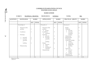
This document outlines the syllabus for the CSEC Technical Drawing exam administered by the Caribbean Examinations Council (CXC). It is divided into three units: Plane and Solid Geometry, Building Drawing, and Mechanical Engineering Drawing. Candidates must complete Unit 1 and either Unit 2 or Unit 3. The exam consists of multiple choice, structured questions, and a School-Based Assessment project. Candidates have the option to complete the exam and project using traditional drawing methods or Computer Aided Drafting.
English SBA for CSEC. *The file has been protected and has been submitted to CXC. Do not copy as the digital signature of the file cannot be removed or edited. Use as a guide only
This document is meant to be used as a guide to current and upcoming students at the CXC CSEC level experiencing difficulty in doing their School Bases Assesment (SBA). This document follows the 2010 syllabus which may be subject to change.
This is the table of contents of the two-volume Canadian National Building Code 2015 issued by by National Research Council Canada. It is a model code which means many local jurisdictions base their own codes on this model across Canada.
There are other model codes too including National Fire Code, the National Plumbing Code, and the National Energy Code for Buildings. They are collectively referred to as Codes Canada.
The codes are published by Codes Canada publications and you have to pay hundreds to access the codes, $295 for a print version or $182 a year online.
Download link: https://www.researchgate.net/publication/318852873_Engineering_Drawing_-_I
DOI: 10.13140/RG.2.2.22512.56328
An engineering drawing is a type of technical drawing, used to fully and clearly define requirements for engineered items, and is usually created in accordance with standardized conventions for layout, nomenclature, interpretation, appearance size, etc.
Its purpose is to accurately and unambiguously capture all the geometric features of a product or a component. The end goal of an engineering drawing is to convey all the required information that will allow a manufacturer to produce that component.
The 2007 Annual Report of the Caribbean Examinations Council (CXC) summarizes the major activities and accomplishments
during the year. The report highlights the Council’s success in administering its major examinations; it speaks to the
accomplishments in each of the five Strategic Goals in 2007
TLE 9 (Technical Drafting) - Occupational Health and SafetyJuan Miguel Palero
It is a powerpoint presentation that discusses about the topic or lesson: Occupational Health and Safety. It also includes some laws about Occupational Health and Safety.
CCP Certification training Course helps you clear CCP Certification Exam. CCP Certification is an experienced practitioner with advanced knowledge and technical expertise to apply the broad principles and best practices of Total Cost Management (TCM) in the planning, execution and management of any organizational project or program. CCPs also demonstrate the ability to research and communicate aspects of TCM principles and practices to all levels of project or program stakeholders, both internally and externally. Our CCP certification Exam preparation course lets you clear your CCP Certification Exam in first attempt!
Synthetic Fiber Construction in lab .pptxPavel ( NSTU)
Synthetic fiber production is a fascinating and complex field that blends chemistry, engineering, and environmental science. By understanding these aspects, students can gain a comprehensive view of synthetic fiber production, its impact on society and the environment, and the potential for future innovations. Synthetic fibers play a crucial role in modern society, impacting various aspects of daily life, industry, and the environment. ynthetic fibers are integral to modern life, offering a range of benefits from cost-effectiveness and versatility to innovative applications and performance characteristics. While they pose environmental challenges, ongoing research and development aim to create more sustainable and eco-friendly alternatives. Understanding the importance of synthetic fibers helps in appreciating their role in the economy, industry, and daily life, while also emphasizing the need for sustainable practices and innovation.
Honest Reviews of Tim Han LMA Course Program.pptxtimhan337
Personal development courses are widely available today, with each one promising life-changing outcomes. Tim Han’s Life Mastery Achievers (LMA) Course has drawn a lot of interest. In addition to offering my frank assessment of Success Insider’s LMA Course, this piece examines the course’s effects via a variety of Tim Han LMA course reviews and Success Insider comments.
June 3, 2024 Anti-Semitism Letter Sent to MIT President Kornbluth and MIT Cor...Levi Shapiro
Letter from the Congress of the United States regarding Anti-Semitism sent June 3rd to MIT President Sally Kornbluth, MIT Corp Chair, Mark Gorenberg
Dear Dr. Kornbluth and Mr. Gorenberg,
The US House of Representatives is deeply concerned by ongoing and pervasive acts of antisemitic
harassment and intimidation at the Massachusetts Institute of Technology (MIT). Failing to act decisively to ensure a safe learning environment for all students would be a grave dereliction of your responsibilities as President of MIT and Chair of the MIT Corporation.
This Congress will not stand idly by and allow an environment hostile to Jewish students to persist. The House believes that your institution is in violation of Title VI of the Civil Rights Act, and the inability or
unwillingness to rectify this violation through action requires accountability.
Postsecondary education is a unique opportunity for students to learn and have their ideas and beliefs challenged. However, universities receiving hundreds of millions of federal funds annually have denied
students that opportunity and have been hijacked to become venues for the promotion of terrorism, antisemitic harassment and intimidation, unlawful encampments, and in some cases, assaults and riots.
The House of Representatives will not countenance the use of federal funds to indoctrinate students into hateful, antisemitic, anti-American supporters of terrorism. Investigations into campus antisemitism by the Committee on Education and the Workforce and the Committee on Ways and Means have been expanded into a Congress-wide probe across all relevant jurisdictions to address this national crisis. The undersigned Committees will conduct oversight into the use of federal funds at MIT and its learning environment under authorities granted to each Committee.
• The Committee on Education and the Workforce has been investigating your institution since December 7, 2023. The Committee has broad jurisdiction over postsecondary education, including its compliance with Title VI of the Civil Rights Act, campus safety concerns over disruptions to the learning environment, and the awarding of federal student aid under the Higher Education Act.
• The Committee on Oversight and Accountability is investigating the sources of funding and other support flowing to groups espousing pro-Hamas propaganda and engaged in antisemitic harassment and intimidation of students. The Committee on Oversight and Accountability is the principal oversight committee of the US House of Representatives and has broad authority to investigate “any matter” at “any time” under House Rule X.
• The Committee on Ways and Means has been investigating several universities since November 15, 2023, when the Committee held a hearing entitled From Ivory Towers to Dark Corners: Investigating the Nexus Between Antisemitism, Tax-Exempt Universities, and Terror Financing. The Committee followed the hearing with letters to those institutions on January 10, 202
Biological screening of herbal drugs: Introduction and Need for
Phyto-Pharmacological Screening, New Strategies for evaluating
Natural Products, In vitro evaluation techniques for Antioxidants, Antimicrobial and Anticancer drugs. In vivo evaluation techniques
for Anti-inflammatory, Antiulcer, Anticancer, Wound healing, Antidiabetic, Hepatoprotective, Cardio protective, Diuretics and
Antifertility, Toxicity studies as per OECD guidelines
Welcome to TechSoup New Member Orientation and Q&A (May 2024).pdfTechSoup
In this webinar you will learn how your organization can access TechSoup's wide variety of product discount and donation programs. From hardware to software, we'll give you a tour of the tools available to help your nonprofit with productivity, collaboration, financial management, donor tracking, security, and more.
Instructions for Submissions thorugh G- Classroom.pptxJheel Barad
This presentation provides a briefing on how to upload submissions and documents in Google Classroom. It was prepared as part of an orientation for new Sainik School in-service teacher trainees. As a training officer, my goal is to ensure that you are comfortable and proficient with this essential tool for managing assignments and fostering student engagement.
Introduction to AI for Nonprofits with Tapp NetworkTechSoup
Dive into the world of AI! Experts Jon Hill and Tareq Monaur will guide you through AI's role in enhancing nonprofit websites and basic marketing strategies, making it easy to understand and apply.
3. CXC 13/O /SYLL 00/A1
iii
Content
Rationale for Teaching Technical Drawing ...................................................................................... 1
General Objectives ..............................................................................................................................1
Organization of the Syllabus...............................................................................................................3-5
Format of the Examination.................................................................................................................5-8
Unit 1 – Plane and Solid Geometry...................................................................................................9-16
Unit 2 – Building Drawing ...............................................................................................................17-20
Unit 3 – Mechanical Engineering Drawing ....................................................................................21-24
Recommended Minimum Equipment /Material for Technical Drawing Syllabus .....................25-27
Recommended Texts...........................................................................................................................28
4. CXC 13/O /SYLL 00/A1
iv
AMENDMENTS
The Technical Drawing Syllabus, previously included in the Industrial Arts Syllabus, is now
published under its own cover. The syllabus was revised in 2000 for first examination in 2002.
The major amendments are indicated by vertical lines.
Attention is drawn to the following:
i) the organisation of the syllabus into Units and Modules;
ii) the merging of the Plane and the Solid Geometry sections into Unit1:
Plane and Solid Geometry;
iii) the revision of the percentage weighting of papers and profile dimensions;
iv) the rewriting of Unit 3: Mechanical Engineering Drawing;
v) the restructuring of the School-Based Assessment component;
vi) the addition of Computer Aided Drafting as an option.
5. Technical Drawing Syllabus
◆RATIONALE FOR TEACHING TECHNICAL DRAWING
It is generally recognised that Technical Drawing is the language of communication of
technical/vocational occupations and as such, has widespread applications in the life of consumers. It
is, therefore, being recommended that every secondary school student should have, at the
minimum, a basic knowledge of Technical Drawing.
To this end, the Caribbean Examinations Council recognises the need to provide a programme of
studies in Technical Drawing which will cater not only to the above stated interest, but also to
those students who will proceed to studies at tertiary levels and/or seek entry level employment in
related fields.
The Technical Drawing course as conceived, therefore, will be an essential companion to the cognate
CSEC Industrial Technology programme as well as an integral component of the General
Education curriculum.
The syllabus also contributes to the development of selected attributes from the CARICOM Ideal Person document as
articulated by the CARICOM Heads of Government. This person is one who demonstrates emotional security with a
high level of self-confidence and self-esteem, is aware of the importance of living in harmony with the environment and
nurtures its development in the economic and entrepreneurial spheres in all other areas of life (CARICOM Education
Strategy, 2000).
This holistic development of students aligns with selected competencies advocated in the UNESCO Pillars of learning.
These are learning to be, learning to do, and learning to transform one’s self and society.
◆GENERAL OBJECTIVES
This syllabus is designed for candidates to:
(i) develop an understanding of and appreciation of Technical Drawing in the Caribbean
Industrial Society;
(ii) discover and develop their talents in the fields of Technical Drawing and related
technologies;
(iii) develop technical problem-solving skills in Technical Drawing as related to materials and
CXC 13/O /SYLL 00/A1
1
6. processes;
(iv) develop the correct and accepted Technical Drawing skills as demanded by Industry;
(v) be aware of the career opportunities available in Technical Drawing and its related fields;
(vi) have a working knowledge and understanding of Computer Aided Drafting applications;
(vii) develop skills to use drawing in the process of design.
◆CERTIFICATION AND DEFINITION OF PROFILES
The Technical Drawing course is an integral component of the Technical/Vocational Education
programme offered by the Council. Commencing May/June 2005, Technical Drawing will be
examined for certification at the General Proficiency only1
. Candidates have the option of
using the Computer-Aided Drafting (CAD) method/application to complete Paper 02,
Paper 03 and the SBA component of the syllabus.
Candidates will be awarded an overall grade reported on a 6-point scale, that is, Grades 1-6. In
addition to the overall grade, candidate’s performance will also be reported under the profile
dimensions, Knowledge, Application and Practical Ability.
Definitions
Knowledge Recall and comprehension of terms, principles, methods, theories
and structures; interpretation and extrapolation;
Application Use of concepts, principles, methods and theories to solve
problems in a given situation; analysis, synthesis and evaluation;
Practical Ability Demonstration of manipulative skills involving the use of drawing
instruments, equipment and materials in problem solving
situations.
CANDIDATE POPULATION
The syllabus is designed to be covered in the final two years of the five-year secondary school
programme and is intended for students enrolled in a full-time programme. However, candidates
who do not attend school full-time may undertake the course by observing the following guidelines:
A. Regulations for Private Institutions
(i) Candidates entering for the examination through private institutions recognized
1
Please refer to letter dated November 4, 2002 to Ministries of Education, Schools and Local Registrars.
CXC 13/O /SYLL 00/A1
2
7. by the Council will be required to complete all the components of the respective
proficiencies.
(i) The School-Based Assessment of such candidates must be monitored by the tutors
in the institution through which they register.
B. Regulations for Private Candidates
(i) “A private candidate is one not entered through a school or other approved
educational institution”.
(ii) A private candidate will be required to complete all the components of the
respective proficiencies.
(iii) A private candidate must identify a teacher/tutor from a registered institution
(school/technical institute/community college) who will assess and approve the
candidate’s submission for the School-Based Assessment component of the syllabus.
The name, school, and territory of the identified teacher/tutor should be submitted
to the Council on registration for the subject.
ALLIED SUBJECTS
School candidates should be encouraged to include the following subjects in their programme of
study: one of the Industrial Technology subjects (Building Technology; Mechanical Engineering
Technology; Electrical and Electronic Technology), English A, Mathematics, Physics.
SUGGESTED TIME ALLOCATION
It is recommended that a minimum of five 40-minute periods per week with no single period be
allocated to the subject over a two-year period.
◆ORGANIZATION OF THE SYLLABUS
The syllabus is divided into three Units:
UNIT 1 - Plane and Solid Geometry
UNIT 2 - Building Drawing
UNIT 3 - Mechanical Engineering Drawing
Candidates are expected to undertake UNIT 1: Plane and Solid Geometry and EITHER UNIT 2:
Building Drawing OR UNIT 3: Mechanical Engineering Drawing.
CERTIFICATION AND DEFINITION OF PROFILES
The Technical Drawing course is an integral component of the Technical/Vocational Education
programme offered by the Council. It will, therefore, be examined for certification at both Basic
and General Proficiencies. Candidates have the option of using either the Traditional Drawing
Method (drawing board and tee square) or Computer Aided Drafting method/applications to
CXC 13/O /SYLL 00/A1
3
8. complete the objectives of the syllabus.
Candidates will be awarded an overall grade reported on a 6-point scale, that is, Grades 1-6. In
addition to the overall grade, candidate’s performance will also be reported under the profile
dimensions, Knowledge, Application and Practical Ability.
DEFINITIONS
Knowledge Recall and comprehension of terms, principles, methods, theories and
structures; interpretation and extrapolation;
Application Use of concepts, principles, methods and theories to solve
problems in a given situation; analysis, synthesis and evaluation;
Practical Ability Demonstration of manipulative skills involving the use of drawing
instruments, equipment and materials in problem solving
situations.
(Distinction between Basic and General Proficiency)
The Basic Proficiency or “Core” syllabus provides the minimum Technical Drawing skills and
competencies.
For the General Proficiency, the syllabus is augmented by additional modules to ensure a more
extensive knowledge and understanding of the subject. General Proficiency candidates will
normally be expected to proceed to further studies in their chosen subject areas and should be able
to respond at a higher level to any of the modules listed in the syllabus, so as to demonstrate their
ability to recall and apply the knowledge gained in the solution of problems of a practical nature.
Accordingly, the examinations for Basic Proficiency and General Proficiency differ in:
(i) the extent of the syllabus content to be covered;
(ii) the degree of difficulty of questions in papers other than Paper 1;
(iii) the relative importance of the three profile dimensions - Knowledge, Application,
Practical Ability;
The syllabus coverage required is as follows:
BASIC PROFICIENCY
UNIT 1: All areas except Module IX, Auxiliary Projections and Module (Plane and
Solid Geometry) XI, Helical Curves.
CXC 13/O /SYLL 00/A1
4
9. EITHER UNIT 2: (Building Drawing)
All areas except detailed section of staircases, walls and floors.
UNIT 3: (Mechanical Engineering Drawing) All areas except Sectional
Assembly Drawings.
GENERAL PROFICIENCY UNIT 1: (Plane and Solid Geometry)
All areas
EITHER UNIT 2: (Building
Drawing) All areas
OR UNIT 3: (Mechanical Engineering
Drawing) All areas
◆ FORMAT OF THE EXAMINATION
BASIC PROFICIENCY
Paper 01 A paper common to Basic and General Proficiencies. Sixty (60)
multiple (¼ hours) choice items on Unit 1 (except Auxiliary Projection, Module IX
and Helical Curves, Module XI) - Knowledge, Application and
Practical Ability will be tested in the approximate ratio 5:4:1. Each item
will be worth one mark.
Paper 02 Plane and Solid Geometry
(1½ hours) Six structured questions on the same Unit as Paper 1 – three
questions will be set on Modules I-VI and three on Modules VII, VIII
and X. Candidates must attempt three questions but not more than
two from any part. Each question will be worth 20 marks distributed in
the approximate ratio: Knowledge 3: Application 7: Practical Ability
10.
Paper 03 Building or Mechanical Engineering Drawing (Traditional)
(2½ hours) Six structured questions testing the objectives of Modules in Unit
2: Building Drawing and Unit 3: Mechanical Engineering Drawing.
Three questions will be set on Building Drawing and three on
Mechanical Engineering Drawing. Candidates must attempt two
questions: one working/assembly drawing and one sketch and design
(from area of choice). The working/assembly drawing will be worth
60 marks of which
10 marks will be for (Knowledge), 20 for (Application) and 30 for
(Practical Ability). The sketch and design question will be worth 20
marks of which 5 will be for (Knowledge), 7 for (Application) and 8 for
(Practical Ability).
CXC 13/O /SYLL 00/A1
5
10. OR
Paper 03 Building or Mechanical Engineering Drawing (Computer)
(2½ hours) Six structured questions testing the objectives of Modules in Unit
2: Building Drawing and Unit 3: Mechanical Engineering Drawing.
Three questions will be set on Building Drawing and three on
Mechanical Engineering Drawing. Candidates must attempt two
questions: one 2D working/assembly drawing and one 3D solid model
design drawing (from area of choice). The working/assembly drawing
will be worth 60 marks of which 10 marks will be for (Knowledge), 20
for (Application) and 30 for (Practical Ability). The solid model design
drawing question will be worth 20 marks of which 5 will be for
(Knowledge), 7 for (Application) and 8 for (Practical Ability).
BASIC PROFICIENCY
School-Based Assessment
During the fourth and fifth terms of the course, candidates will be required to complete a project
testing the candidates’ ability to design/redesign a Building component or Mechanical Engineering
device/gadget to solve a simple functional problem in one of the ten categories, viz:
Categories
I) Household vi) Business/Office
ii) Education facilities vii) Power
iii) Agriculture/Fishing viii) Recreation
iv) Health facilities ix) Construction
v) Transportation x) Manufacturing
The drawing project will carry 50 marks – 5 for Knowledge, 20 for Application and 25 for Practical
Ability and will account for 20% of the composite score.
Candidates will be required to prepare a complete set of working drawings of the Building component
or Mechanical Engineering device/gadget. Sketches, working/assembly drawings should be kept in a
portfolio (laboratory book) which will be assessed by the teacher.
NB: The drawing project must be done in its entirety in the classroom/laboratory under the
supervision of a teacher. It is anticipated that the project will not be done under examination
conditions. However, the teacher is expected to ensure that the project is developed under
his/her supervision and reflects solely the candidate’s efforts. Candidates selecting the
Traditional Drawing Method may complete the SBA drawing project using the Computer
Aided Drafting Method/applications.
CXC 13/O /SYLL 00/A1
6
11. GENERAL PROFICIENCY
Paper 01 A paper common to Basic and General Proficiencies. Sixty (60) multiple (1¼
hours) choice items on Unit 1 (except Auxiliary Projection Module IX and
Helical Curves Module XI) – Knowledge, Application and Practical Ability
will be tested in the approximate ratio 5:4:1. Each item will be worth
one mark.
Paper 02 Plane and Solid Geometry
(1½ hours) Eight questions on Modules of Unit 1– four questions will be set on
Modules I – VI and four on Modules VII - XI. Candidates must attempt four
questions, two from each part. Each question will be worth 20 marks
distributed in the ratio 4:7:9 for (Knowledge), (Application), and (Practical
Ability).
Paper 03 Building and Mechanical Engineering Drawing (By Traditional Method)
(3 hours) Eight questions testing the objectives of Modules in Unit 2: Building
Drawing and Unit 3: Mechanical Engineering Drawing of the syllabus. Four
questions on Building Drawing and four questions on Mechanical Engineering
Drawing. Candidates must attempt two questions: one sectional
working/assembly drawing and one sketch and design from area of choice. The
sectional working/assembly drawing question will be worth 80 marks of
which 16 will be for (Knowledge), 32 for (Application) and 32 for (Practical
Ability). The sketch and design question will be worth 20 marks of which 3
will be for (Knowledge), 7 for (Application) and 10 for (Practical Ability).
OR
Paper 03 Building and Mechanical Engineering Drawing (By Computer)
(3 hours) Eight questions testing the objectives of Modules in Unit 2: Building
Drawing and Unit 3: Mechanical Engineering Drawing of the syllabus.
Four questions on Building Drawing and four questions on Mechanical
Engineering Drawing. Candidates must attempt two questions: one
sectional 2D working/assembly drawing and one 3D solid model design
drawing from area of choice. The sectional working/assembly drawing
question will be worth 80 marks of which 16 will be for (Knowledge), 32
for (Application) and 32 for (Practical Ability). The 3D solid model and
design drawing question will be worth 20 marks of which 3 will be for
(Knowledge), 7 for (Application) and 10 for (Practical Ability).
SCHOOL-BASED ASSESSMENT
Apart from the allocation of marks, the project is the same as for the Basic Proficiency. However,
candidates must include a full or part sectional view of the fully assembled component or
device/gadget for the Building or Mechanical Engineering Unit. The project will carry 60 marks –
6 for Knowledge, 24 for Application and 30 for Practical Ability and will account for 20% of the
composite score.
CXC 13/O /SYLL 00/A1
7
12. REGULATIONS FOR RESIT CANDIDATES
Resit candidates who obtained 50% or more of the SBA total may choose not to repeat their SBA
provided that they rewrite the examination not later than the subsequent year.
Candidates who obtained less than 50% of the total SBA marks must be re-assessed during Terms 1
and 2 of the year of the examination.
WEIGHTING
The percentage weighting of the examination components is as follows:
Paper 1
Basic
24
General
20
Paper 2 24 27
Paper 3 32 33
School-Based
Assessment
20 20
DISTRIBUTION OF MARKS BY PAPER AND PROFILE
Profiles
Basic Proficiency General Proficiency
Paper 1 Paper 2 Paper 3 SBA Total Paper 1 Paper 2 Paper 3 SBA Total
Knowledge 30 9 15 5 59 30 16 19 6 71
Application 24 21 27 20 92 24 28 39 24 115
Practical
Ability
6 30 38 25 99 6 36 42 30 114
60 60 80 50 250 60 80 100 60 300
The percentage weighting of the Profile dimensions is as follows:
Profile Basic General
Knowledge 24 24
Application 37 38
Practical Ability 39 38
CXC 13/O /SYLL 00/A1
8
13. ◆ UNIT 1: PLANE AND SOLID GEOMETRY
MODULE I
INSTRUMENTS, LETTERING,
LINES, DIMENSIONS, SCALES
SPECIFIC OBJECTIVES
The student should be able to:
1. identify common
drawing instruments
and equipment and
state their uses;
2. layout drawing sheet;
3. draw and state the name
and applications of the
types of line used in
drawing;
4. letter and dimension
drawings;
5. log on to system
network;
6. practice basic
Computer Aided
Drafting operations.
CONTENT
Common drawing instru-
ments: T-squares, set squares,
scales, pencils, dividers,
compasses, protractors,
irregular curves.
Alphabet of lines.
Lettering: styles, guidelines,
sizes, composition in lettering
Dimensioning: lines and
symbols, sizes of dimensions,
location, standard detail.
System in laboratory: CPU,
monitor, keyboard, mouse,
printer, plotter; protective
devices: voltage regulator, serge
protector, UPS; care and safety
of equipment and Computer
software..
Advantages of using
Computer Aided Drafting
software, Drafting terms:
cursor, left-click, right-click,
double-click, drag, select, pick,
pick button, pick box, return,
enter, Esc, tool, icon, tool tip,
flyout, coordinate system, line
commands, screen control,
entering distances using direct
distance entry and rectangular
and polar coordinate methods.
CXC 13/O /SYLL 00/A1
9
14. MODULE I
INSTRUMENTS, LETTERING,
LINES, DIMENSIONS, SCALES
CONT’D
MODULE II
GEOMETRIC
CONSTRUCTIONS
MODULE III
CONSTRUCTION OF
POLYGONS
SPECIFIC OBJECTIVES
The student should be able to:
1. bisect straight lines,
arcs and angles;
2. draw perpendicular to a
given line, at a point on
the line or from a point
outside the line;
3. draw a line parallel to a
given line.
4. divide straight lines and
angles geometrically;
5. copy any given angle.
The student should be able to:
1. construct triangles given:-
three sides; two angles
and one side; two sides
and included angle;
perimeter and proportion
of sides; altitude and base
angles; perimeter and
base angles;
2. construct a square given
the length of one side
and the diagonal;
CONTENT
adjusting drawing limits,
drawing lines, drawing circles,
object snap, power snap,
dimensioning. Saving and
printing drawing.
Geometrical terms: bisector,
angle, perpendicular, parallel,
arc.
Angles: definitions and types;
acute, right, obtuse, straight
line.
Characteristics of lines in
drawing.
Proportional division of lines
and angles.
Triangles: definitions and
parts of. Types of triangles:
right angled, equilateral,
isosceles, scalene, ambiguous
case. Necessary data for the
construction of triangles.
Methods of construction of
various types of triangles.
Quadrilaterals: squares,
rectangles, parallelograms
CXC 13/O /SYLL 00/A1
10
15. MODULE III
CONSTRUCTION OF
POLYGONS CONT’D
SPECIFIC OBJECTIVES
The student should be able to:
3. construct a rectangle
given the length of the
diagonal and one side;
4. construct a parallelo-gram
given the lengths of two
adjacent sides and an
angle;
5. construct a rhombus
given the length of one
diagonal and the length
of one side;
6. construct a trapezium
given the lengths of the
sides, the perpendicular
distance between them
and one angle.
7. Construct a regular
hexagon and octagon
given the distance across
flats (A/F); distance
across corners (A/C);
8. construct any regular
polygon given the length
of a side;
9. construct any regular
polygon within a given
circle;
10. construct any irregular
polygon given the length
of the sides and the
included angles;
CONTENT
Properties and identification
of geometrical shapes.
Necessary data for the
construction of any
quadrilateral.
Polygons: definition and types
- pentagon, hexagon and
octagon
Necessary data for
construction of any regular
polygon.
Necessary data for
construction of any irregular
polygon.
CXC 13/O /SYLL 00/A1
11
16. MODULE IV
CIRCLES, ARCS, CURVES
AND TANGENTS
SPECIFIC OBJECTIVES
The student should be able to:
1. construct circles given
diameter or circum-
ference;
2. construct a circle to pass
through - three given
points; a fixed point and
touching a line at a given
point; two given points
and touching a given line;
two given points and
touching a given circle;
3. draw three circles which
touch each other given
the positions of the three
centres;
4. construct the inscribed,
circumscribed and
escribed circles of any
given triangle and any
given regular polygon.
5. inscribe the largest square
within a triangle with one
side lying on a side of the
triangle;
6. draw arcs tangential to
two straight lines at
acute, right and obtuse
angles;
CONTENT
Definition of a circle: parts of
a circle - diameter, radius, arc,
chord, quadrant. Properties of
a circle.
Construction of circles.
Relationship of the bisectors
of the interior angles to the
inscribed circle.
Definition of inscribed,
circumscribed and escribed
circles.
Relationship between the
perpendicular bisector of a
line and the circumscribed
circle.
Arcs and their relationship to
the circle.
CXC 13/O /SYLL 00/A1
12
17. MODULE IV
CIRCLES, ARCS, CURVES
AND TANGENTS
CONT’D
MODULE V
EQUIVALENT AREAS;
REDUCING AND ENLARGING
PLANE FIGURES
SPECIFIC OBJECTIVES
The student should be able to:
7. draw tangents to - a circle
at a given point on the
circumference; a circle
from any given point
outside of the circle; two
given circles;
8. construct the common
internal and external
tangents to two given
circles;
9. draw an arc tangential to
two given circles of
different radii.
The student should be able to:
1. construct rectangles equal
in area to triangles;
squares equal in area to
rectangles and triangles;
triangles equal in area to
quadrilaterals and
polygons; squares equal
in area to quadrilaterals
and polygons;
2. determine areas of plane
figures graphically;
3. divide triangles and
polygons into a number
of equal parts by drawing
lines parallel to one side;
4. reduce and enlarge plane
figures by linear measure-
ments or ratio of sides;
ratio of areas;
CONTENT
Definition of a tangent.
Tangencies of circles, arcs and
straight lines and their
practical applications.
Internal and external tangents
and their applications. Centres
and tangency points.
Areas of triangles, squares,
rectangles, quadrilaterals, and
polygons.
Graphical determination of
areas of laminae and
combined plane figures.
Similar triangles and pro-
portional figures.
Principles involved in reducing
and enlarging areas of figures.
CXC 13/O /SYLL 00/A1
13
18. MODULE VI
LOCI
MODULE VII
PICTORIAL DRAWINGS
SPECIFIC OBJECTIVES
The student should be able to:
1. draw an ellipse by the foci,
trammel, concentric circles
and rectangular methods;
and construct normal and
tangent at a point on the
curve;
2. draw by the focus method:
parabola; hyperbola;
3. draw the involute of a
square and a circle;
4. plot and trace the loci of
given points;
5. plot and trace the loci in a
simple crank mechanism;
6. draw an Archimedean
Spiral;
7. draw cycloidal curves.
The student should be able to:
1. draw isometric, oblique
and 1-and 2-point
perspective drawings of
geometric solids and
simple models.
CONTENT
Conic sections – relation-ships
Ellipse: definitions and
properties. The ellipse as loci
of a moving point. Methods
of construction of the ellipse.
Parts of the ellipse: major and
minor axes, directrix, vertices,
focus.
Parabola and hyperbola:
definition and properties.
Methods of construction of
the parabola and hyperbola.
Parts of parabola and
hyperbola: vertices, directrix,
focus, ordinate.
Involute of a circle.
Simple loci problems with
practical applications.
Archimedean Spiral. Parts of a
spiral: pole, radius, vector,
convolution.
Cycloidal curves and their
applications.
Principles of pictorial drawings
- isometric, oblique and pers-
pective geometric solids: cones,
prisms, pyramids, cylinders,
simple models, blocks,
isometric circles. Free hand
pictorial sketches.
CXC 13/O /SYLL 00/A1
14
19. MODULE VII
PICTORIAL DRAWINGS
CONT'D
MODULE VIII
ORTHOGRAPHIC
PROJECTION
MODULE IX
AUXILIARY PROJECTIONS
SPECIFIC OBJECTIVES
The student should be able to:
1. draw orthographic
projections of geometric
solids and simple models
using First angle or Third
Angle projection;
The student should be able to:
1. draw primary auxiliary
views by projection;
2. determine the true
lengths of straight lines
by revolution and
auxiliary methods;
3. determine true shapes of
laminae by auxiliary
projections;
4. determine the true shapes
of sectioned surfaces of
geometric solids;
5. construct curves of
interpenetration of
geometric solids with
their axes in the same
plane;
CONTENT
Using Drawing Aids: grid,
snap, isoplane settings.
Planes of projection:
horizontal and vertical planes.
Plans and elevations.
Free hand orthographic
Auxiliary planes of projection -
oblique planes inclined to
both horizontal and vertical
planes.
Straight lines and laminae
inclined to both horizontal
and vertical planes.
Cones, cylinders, prisms and
pyramids.
Solids with axes in the same
plane, cylinder/cylinder,
prism/prism, prism/cylinder.
CXC 13/O /SYLL 00/A1
15
20. MODULE X
SURFACE DEVELOPMENTS
MODULE XI
HELICAL CURVES
SPECIFIC OBJECTIVES
The student should be able to:
1. draw surface
developments of right
geometric solids;
2. draw surface develop-
ments of sectioned right
geometric solids;
The student should be able to:
1. draw helical spring of
circular cross-section;
2. construct a single helical
curve on a cylinder;
CONTENT
Cones, cylinders, prisms,
pyramids.
Frusta of cones, pyramids,
prisms, cylinders and sheet
metal joints, bends, knees.
Helix curve, pitch, lead.
CXC 13/O /SYLL 00/A1
16
21. ◆ UNIT 2: BUILDING DRAWING
MODULE I
BUILDING CODES AND
MATERIALS
MODULE II
SITE WORK
SPECIFIC OBJECTIVES
The student should be able to:
1. demonstrate the
application of Building
codes as they apply to
standard building
drawing procedures;
2. prepare a drawing sheet;
3. demonstrate standard
architectural practice;
4. prepare drawings to given
scales;
5. produce 2D and 3D solid
model drawings of a
building or its
components.
The student should be able to:
1. prepare working plans
of building sites;
2. prepare site plans;
CONTENT
Building code regulations, for
example, set backs, road sizes,
verge, water zones.
Borders, title blocks
Standard drawing practice, for
example, lines weight, letter-
ing, symbols, conventions.
Sketching in proportion,
working drawings to scale.
Drawing Aids, drawing
construction lines (c-lines)
using cross, parallel with full
distance, drawing outline,
inserting dimension, hatching,
using mirror copy, saving &
printing .
Importance of site investi-
gation. Common site
clearance practices: demolish-
ing, salvaging, cutting,
burning, earth-moving and
disposing.
Factors important to site
layout: slope, layout of land,
drainage, sewer disposal,
fencing, locating boundaries,
building regulations for site
layout. Components of site
plans. Elementary intro-
duction to sub-soils.
CXC 13/O /SYLL 00/A1
17
22. MODULE III
FOUNDATIONS
MODULE IV
FLOOR PLANS AND
ELEVATIONS
MODULE V
FLOORS
SPECIFIC OBJECTIVES
The student should be able to:
1. prepare simple working
drawings of foundation
work;
2. prepare sketches for
concrete foundations of
buildings;
3. prepare sketches for
simple reinforcement of
foundation work;
4. prepare drawings of
common footings used in
building construction;
5. draw foundation plans;
The student should be able to:
1. design and layout a
simple floor plan from
given specifications;
2. make a freehand sketch
of a floor plan;
3. draw floor plans to given
scales;
4. draw elevations of
buildings;
The student should be able to:
1. prepare drawings show-
ing various types of floor
and floor section;
CONTENT
Simple concrete foundations
for level and sloping ground.
Simple reinforcement , ortho-
graphic pictorial and freehand
sketches
Instrument drawings/section
details
Position of foundation wall,
footing.
Orientation and relationship
of rooms, positioning of walls,
windows, doors, stairs, arches,
bathroom and kitchen
symbols. Linework, dimen-
sioning annotation. Measur-
ing to scale.
Projections and orientation,
ground line, floor line, doors
and windows in elevation,
height of roof, fascia eave,
rendering.
Solid, hollow and suspended
ground floor, floor covering,
for example, tiles, screed.
CXC 13/O /SYLL 00/A1
18
23. MODULE VI
INTERNAL AND EXTERNAL
WALLS AND FINISHING
MODULE VII
ROOFS
SPECIFIC OBJECTIVES
The student should be able to:
1. draw details of various
types of wall;
2. differentiate between
internal and external load
bearing and non-load
bearing walls;
3. draw detailed framed
timber partition;
4. make working drawings
of wall details;
The student should be able to:
1. draw plan and elevations
of various types of roof
and roof structure;
2. prepare working drawings
of roof anchorage systems;
3. prepare a working drawing
of a roof showing truss
details;
4. prepare working drawings
showing open and closed
eaves;
CONTENT
Stone rubble walls
Concrete block walls
Brick walls
Composite walls
Internal and external
rendering; sectional details
Load and non-load bearing
walls constructions in blocks
and timber.
Treatment of openings in wall.
Plastering to walls and ceilings.
Internal and external
renderings. Sectional details.
Common types of roofs found
in the region. Roof terms:
ridgeplate, common rafters,
hip rafters, valley rafters. Flat
roofs in timber and their
coverings, gable-end roofs.
Pitched roof construction with
various coverings. Treatment
of gutters, parapets and
ventpipes.
Methods of anchorage,
hurricane clips/straps, bolts
Simple contemporary timber
trusses.
Eave details, dimensioning
and annotations.
CXC 13/O /SYLL 00/A1
19
24. MODULE VIII
DOORS AND WINDOWS
MODULE IX
STAIRWAYS
MODULE X
SECTIONS
SPECIFIC OBJECTIVES
The student should be able to:
1. prepare drawings
showing various types of
door and window and
their fittings;
2. draw a detailed section of
a sliding window in a
masonry wall;
3. prepare typical sectional
drawings to show door
and window details;
The student should be able to:
1. draw stairs and calculate
risers from given heights;
2. prepare drawings of
common inside stairway;
3. prepare a sectional
working drawing of a
straight flight staircase;
4. prepare a detailed
drawing of the parts of a
step;
The student should be able to:
1. prepare full sectional drawings
of single-storey buildings;
CONTENT
Internal and external doors
with linings and frames.
Common types of windows.
Horizontal and vertical sliding
windows.
Window casements, iron-
mongery and louvres.
Positioning of hinges and
locks.
Principles of construction of
straight flight stairs – both
timber and simple reinforced
concrete.
Using principles of ortho-
graphic projection: found-
ation, floors, walls, roofs.
CXC 13/O /SYLL 00/A1
20
25. ◆ UNIT 3: MECHANICAL ENGINEERING DRAWING
MODULE I
PREPARATION OF
DRAWING SHEET
SPECIFIC OBJECTIVES CONTENT
The student should be able to:
1. prepare drawing sheet
with appropriate title
block.
B.S. 308 1984 parts 1 & 2;
Engineering Drawing Office
Practice - PD 7308; ISO 9000;
Title of Drawing, Scale, Date
of Drawing, Name of
Draftsman, Drawing number,
Revisions, Symbol of
Projection, Lettering; Size of
Drawing Sheets, Use of
Guidelines.
MODULE II
ORTHOGRAPHIC
PROJECTION
The student should be able to:
1. draw orthographic
views in first-angle or
third-angle projection
of simple machine
parts and components;
2. use machining
symbols on machine
parts and
components;
3. prepare scaled
orthographic views in
first-angle or third-
angle projection of
simple machine parts
and components;
Orthographic views in First or
Third Angle Projection of vee
blocks, plummer block, tool
holders, tool post, connecting
rod, pulley frame, pulleys,
pulley yoke, lever bracket,
machine vice body, shaft
bearing, angle plate base, pivot
block, bearing block, axle
support.
Machined surfaces.
Scales: Reduction 1:2; 1:5;
1:25; 1:50; 1:100:, 1:500. Scale:
Enlargement: 2:1, 5:1, 10:1,
25:1, 50:1, 100:1. Diagonal
scale. Indicate scale used.
CXC 13/O /SYLL 00/A1
21
26. MODULE II SPECIFIC OBJECTIVES CONTENT
ORTHOGRAPHIC
PROJECTION CONT’D The student should be able to:
Drawing construction lines (c-
lines) using cross, parallel with
full distance, drawing outline,
inserting dimension; mirror
copy drawing, inserting angle
dimension, drawing centre
lines, drawing and dimension-
ing fillets & chamfer, drawing
tangent lines, break objects,
hatching, surface texture
symbols, leader lines. hidden
detail lines, use of shaft
generator, saving & printing
drawing.
MODULE III
ENGINEERING
CONVENTIONS
The student should be able to:
1. apply conventional
representations for
machine parts,
components;
2. dimension drawings;
3. apply conventional
representation of
welding and brazing
symbols on fabricated
machine parts and
components.
Conventional representation
of bearings, metric screw
thread, shafts, springs, gears,
knurl, flat on round, square,
lap, countersink, counterbore,
spot face, chamfer, bevel,
tubular sections.
Stop (Extension) lines,
dimension lines, arrowheads,
leaders, overall dimensions,
chain dimensioning, linear
dimensioning, dual dimension-
ing, angular dimensioning,
arrangement of dimensions,
toleranced dimensions, radius,
diameter, circles, arcs, metric
screw threads.
Welding and brazing symbols.
CXC 13/O /SYLL 00/A1
22
27. MODULE IV
SECTIONS
SPECIFIC OBJECTIVES
The student should be able to:
1. prepare sectional
drawings of simple
machines, machine
parts and com-
ponents;
CONTENT
Types of sections: full, half,
part, off-set, revolved, removed,
local, sectional plan and
elevations of vee block,
plummer block, connecting
rod, pulleys, lever bracket,
machine vice body, shaft
bearing, angle base plate,
support block, support arm,
support plate, brackets, jig
body, shaper quadrant, tension
block, bearing block, lathe tool
post, link connector, com-
pound rest, crank;
MODULE V
ENGINEERING FASTENERS
The student should be able to:
1. make orthographic
drawings and free-
hand sketches of
engineering
fasteners;
Engineering fasteners: Tem-
porary fasteners: nuts and
bolts, screws, studs, cotters,
locknuts, slotted nuts, castle
nut, self-locking nut, spring
washers, saddle keys, round
keys, feather keys, parallel keys,
taper keys, woodruff keys, split
pins; Permanent fasteners:
rivets, conventional
representation of welds, and
brazings: fillet, vee, butt, spot.
Indication of direction, site
and location of weld.
MODULE VI
ASSEMBLY DRAWINGS
The student should be able to:
1. draw plan and
elevations in first-
angle or third-angle
projection of
assembled machine
parts and
components;
Assemblies of shaft and pulleys,
casters, jigs and fixtures,
machine and bench vices,
bearing assemblies, universal
couplings, lathe steady, pulley
and hook, shaft block and
bearing, tool supports and
CXC 13/O /SYLL 00/A1
23
28. MODULE VI
ASSEMBLY DRAWINGS
CONT’D
SPECIFIC OBJECTIVES
The student should be able to:
2. Draw sectional plans
and elevations of
assembled machine
parts;
3. Read and prepare
working drawings of
machine parts and
components;
CONTENT
holders, lathe tail stock, valve
link connector, connecting rod
and bearing, screw jack,
scribing block, clamping
devices, vee block and clamp,
crank and pin, footstep bearing,
clapper box, eccentrics, tool
rest, pipe vice, swivel.
Parts list given machine
components showing Part. No.,
Name of Part, Number
required, Material, Remarks,
balloon referencing.
4. Prepare parts list of
machine components.
MODULE VII
SKETCHING
The student should be able to:
1. make freehand
sketches of engineering
components;
2. produce 3D solid model
drawing. of engineering
components.
Sketching of engineering
features using standard
graphic symbols, sectional
assemblies;
Shaped blocks, chisels,
punches, nuts and bolts,
hammers, saws, vee block,
clamps, mallets, anvil, lathe
tools, drill bits, taps and dies,
reamers, welded joints, lathe
tail stock, lathe centres,
spanners, wrenches, tri-square,
snips, stakes, hand groover,
rivet snap, tap wrench.
Using drawing aids: grid, snap,
isoplane setting.
CXC 13/O /SYLL 00/A1
24
29. ◆ SCHOOL-BASED ASSESSMENT
RATIONALE
School-Based Assessment (SBA) is an integral part of student assessment in the coursecovered
by this syllabus. It is intended to assist students in acquiring certain knowledge, skills and
attitudes that are associated with the subject. The activities for the SBA are linked to the
syllabus and should form part of the learning activities to enable the student to achieve
the objectives of the syllabus.
During the course of study for the subject, students obtain marks for the competence they
develop and demonstrate in undertaking their SBA assignments. These marks contribute
to the final marks and grades that are awarded to students for their performance in the
examination.
The guidelines provided in this syllabus for selecting appropriate tasks are intended to assist teachers and students in
selecting assignments that are valid for the purpose of SBA. The guidelines provided for the assessment of the
assignments are intended to assist teachers in awarding marks that are reliable estimates of the achievement of
students in the SBA component of the course. In order to ensure that the scores awarded by teachers are
consistent with the CXC standards, the Council undertakes the moderation of a sample of the SBA
assignments marked by each teacher.
School-Based Assessment provides an opportunity to individualise a part of the curriculum to meet the needs of
students. It facilitates feedback to the student at various stages of the experience. This helps to build the self-
confidence of students as they proceed with their studies. School-Based Assessment also facilitates the
development of the critical skills and abilities emphasised by this subject and enhances the validity of the
examination on which candidate performance is reported. School-Based Assessment, therefore, makes a
significant and unique contribution to both the development of relevant skills and the testing and rewarding of
students for the development of those skills.
GENERAL PROFICIENCY
During the fourth and fifth terms of the course, candidates will be required to complete a project
testing the candidates’ ability to design/redesign a Building component or Mechanical Engineering
device/gadget to solve a simple functional problem in one of the ten categories, namely:
Categories
i) Household vi) Business/Office
ii) Education facilities vii) Power
iii) Agriculture/Fishing viii) Recreation
iv) Health facilities ix) Construction
v) Transportation x) Manufacturing
Candidates will be required to prepare a complete set of working drawings of the Building
component or Mechanical Engineering device/gadget. Sketches, working/assembly drawings should
be kept in a portfolio (laboratory book) which will be assessed by the teacher. Candidates must
include a full or part sectional view of the fully assembled component or device/gadget for the
Building or Mechanical Engineering Unit. The project will carry 60 marks – 6 for Knowledge,
CXC 13/O /SYLL 00/A1
25
30. 24 for Application and 30 for Practical Ability and will account for 20% of the composite score
(See page 4 of this document for detailed criteria and mark scheme).
NB: The teacher should prepare candidates for the drawing project by discussing with
them the stages in the design process: recognition of need; definition of problem;
illustration of various aspects of solution; selection of best solution; evaluation of
selected solution; and presentation of chosen solution.
The drawing project must be done in its entirety in the classroom/laboratory.
Since this project is part of School-Based Assessment, it must be done under the
guidance of the teacher but must be the candidate’s own work.
Candidates who opt to use the Traditional Drawing Method for Paper 02 and
Paper 03 may, nevertheless, opt to do the SBA drawing project using the Computer
Aided Drafting method/application.
◆ RECOMMENDED MINIMUM EQUIPMENT/MATERIAL FOR
TECHNICAL DRAWING SYLLABUS
TRADITIONAL DRAWING METHOD (For a Class of 20)
Any suitable classroom can be converted into a Drawing Room with the addition of Drawing
Boards.
EQUIPMENT QUANTITY
1. Drawing boards 20
OR
Dual drawing desks 10
OR
Drawing tables 20
2. Half imperial tee-squares 20
3. Pair of set squares 20
4. Protractors, scales and french curves 20
5. Pair of drawing clips 20
6. Set of drawing instruments 20
In addition, students will be required to have the following:
(a) A hand towel or cheese cloth;
(b) A good eraser;
(c) Pencil – grades HB, F, H 2H.
CXC 13/O /SYLL 00/A1
26
31. COMPUTER AIDED DRAFTING METHOD (For a Class of 10)
It is the responsibility of schools that select the Computer Aided Drafting option to ensure that the
required hardware and software are in place to achieve the objectives of the syllabus.
Recommended Hardware
1. PC fitted with an Intel 80486 or Pentium CPU with the following features: 10
- a minimum of 16 Mbytes memory (RAM);
- hard disk with at least 70 Mbytes of free space to allow Computer Aided Drafting files to
load.
2. A 17 inch VGA monitor 10
3. Mouse & Keyboard 10 each
4. Laser Printer 1
5. Plotter 1
6. UPS/other power protection devices
Recommended Software
1. AutoCAD
OR
2. AutoCAD LT for Windows 95/98.
OR
3. Any other Computer Aided Drafting software package offering the advanced features required
to complete the syllabus objectives.
NB: The School Edition of the software package selected should be purchased to facilitate its
( legal) use on multiple computers.
CXC 13/O /SYLL 00/A1
27
32. ◆ RECOMMENDED TEXTS
Bankhole, A. & Bland S. Technical Drawing 2 Mechanical Drawing,1990. Essex: Longman
Group UK Limited, ISBN 0-582-58857-X.
Boycott, R.W. & Bolan, J. Graphics & Design,1985. London: Edward Arnold (Publishers)
Ltd., ISBN 0-7131-0978-5.
Morling, K. Geometric and Engineering Drawing (2nd Edition), 1991. Edward
ArnoldLondon, ISBN0-7131-3319-8.
Yarwood, A. Technical Drawing With Design, 1994. The Macmillan Press Ltd.,
London, ISBN 0-333-60161-0.
Yarwood, A. An Introduction to AutoCAD Release 14, 1998. Addison Wesley
Longman Ltd., England, ISBN 0-582-32656-7.
Yarwood, A. An Introduction to AutoCAD LT for Windows 95, 1996. Addison
Wesley Longman Ltd., England, ISBN 0-582-30505-5.
Engineering Drawing Practice Parts 1 & 2. British Standards
Institution, 2 Park Street, London WIA 2BS.
Bankhole, A. & Bland S. Technical Drawing 1: Plane and Solid Geometry,1991. Longman,
ISBN0-582-65199-5.
Scoa, E. Technical Drawing 3: Building Drawing 1992. Longman ISBN
0-582-65140-9.
Maguire, D & Simmons C. A Manual of Engineering Drawing, 1995. Edward Arnold, London.
Western Zone Office
March 31, 2000
CXC 13/O /SYLL 00/A1
28
33. 29CXC13/O/SYLL00/A1
CARIBBEAN EXAMINATIONS COUNCIL
WESTERN ZONE OFFICE
MARK SCHEME
SUBJECT: TECHNICAL DRAWING PROFICIENCY: GENERAL PAPER: SBA
QUESTION KNOWLEDGE MARKS APPLICATION MARKS PRACTICAL ABILITY MARKS
B/D TOTAL B/D TOTAL B/D TOTAL
Knowledge of:
- Statement of the
problem
- Conditions
- Drawings:
• pictorial;
• sectional
assembly
/
working
- Dimensioning
1
1
1
2
1
Principles of :
- Statement of the
problem
• specific
- Conditions
• operation
- Drawings:
• pictorial
• sectional
assembly
/
working
- Design:
• function
• safety
• suitability of
materials
- Dimensioning
5
5
2
4
6
2
Accuracy of:
- Design
- Drawings:
• pictorial
• sectional
assembly/
working
- Dimensions
- Dimensioning
Techniques
- Linework/Linetype
• outline
• centre line
• hidden line
• hatching
line
- Text/print
• name of
project
• category
- Neatness/CA
D presentation
6
3
5
4
2
4
2
4
6 24 30
Western Zone Office
2005-02-18