The document provides information about a course on Computer Aided Engineering Drawing. It includes 5 modules that cover topics like basic drawing principles, orthographic projections, isometric projections, development of surfaces, and multidisciplinary applications. Students will learn to generate drawings using manual techniques and CAD software. By the end of the course, students will be able to draw objects, recognize shapes through different views, develop object surfaces, create CAD drawings, and understand engineering components through diagrams. Student work will be evaluated continuously and through tests, while a semester exam will also be administered.
Module 5: Multidisciplinary Applications & Practice (For CIE Only):
Free hand Sketching:
True free hand,
Guided Free hand,
Roads,
Buildings,
Hand tools &
Furniture’s etc
Drawing Simple Mechanisms:
Bicycles,
Tricycles,
Gear trains,
Ratchets,
Two wheeler cart &
Four wheeler carts to dimensions etc
Electric Wiring and lighting diagrams:
Automatic fire alarm,
Call bell system,
UPS system,
Basic power distribution system using suitable software.
Basic Building Drawing:
Architectural floor plan,
basic foundation drawing,
Steel structures-
Frames,
bridges,
Trusses using Auto CAD or suitable software,
The French Revolution, which began in 1789, was a period of radical social and political upheaval in France. It marked the decline of absolute monarchies, the rise of secular and democratic republics, and the eventual rise of Napoleon Bonaparte. This revolutionary period is crucial in understanding the transition from feudalism to modernity in Europe.
For more information, visit-www.vavaclasses.com
The Art Pastor's Guide to Sabbath | Steve ThomasonSteve Thomason
What is the purpose of the Sabbath Law in the Torah. It is interesting to compare how the context of the law shifts from Exodus to Deuteronomy. Who gets to rest, and why?
How to Make a Field invisible in Odoo 17Celine George
It is possible to hide or invisible some fields in odoo. Commonly using “invisible” attribute in the field definition to invisible the fields. This slide will show how to make a field invisible in odoo 17.
Model Attribute Check Company Auto PropertyCeline George
In Odoo, the multi-company feature allows you to manage multiple companies within a single Odoo database instance. Each company can have its own configurations while still sharing common resources such as products, customers, and suppliers.
Palestine last event orientationfvgnh .pptxRaedMohamed3
An EFL lesson about the current events in Palestine. It is intended to be for intermediate students who wish to increase their listening skills through a short lesson in power point.
How to Create Map Views in the Odoo 17 ERPCeline George
The map views are useful for providing a geographical representation of data. They allow users to visualize and analyze the data in a more intuitive manner.
Instructions for Submissions thorugh G- Classroom.pptxJheel Barad
This presentation provides a briefing on how to upload submissions and documents in Google Classroom. It was prepared as part of an orientation for new Sainik School in-service teacher trainees. As a training officer, my goal is to ensure that you are comfortable and proficient with this essential tool for managing assignments and fostering student engagement.
Welcome to TechSoup New Member Orientation and Q&A (May 2024).pdfTechSoup
In this webinar you will learn how your organization can access TechSoup's wide variety of product discount and donation programs. From hardware to software, we'll give you a tour of the tools available to help your nonprofit with productivity, collaboration, financial management, donor tracking, security, and more.
Unit 8 - Information and Communication Technology (Paper I).pdfThiyagu K
This slides describes the basic concepts of ICT, basics of Email, Emerging Technology and Digital Initiatives in Education. This presentations aligns with the UGC Paper I syllabus.
Home assignment II on Spectroscopy 2024 Answers.pdf
22CED13.pdf
1. Page 1 of 4
Course Title: Computer Aided Engineering Drawing
Course Code 22CAED13/23 CIE Marks 50
Teaching Hour/Week (L:T:P:S) 2:0:2:0 SEE Marks 50
Total Hours of Teaching - Learning 40 Total Marks 100
Credits 03 Exam Hours 03
Course Learning Objectives:
CLO1: To understand the basic principles and conventions of engineering drawing
CLO2: To use drawing as a communication mode
CLO3: To generate pictorial views using CAD software
CLO4: To understand the development of surfaces
CLO5: To visualize engineering components
Teaching-Learning (General Instructions):
• Students should be made aware of powerful engineering communication tool – Drawing.
• Simple Case studies can be suitably selected by the teacher for hands on practice to induce the feel of
fruitfulness of learning.
• Appropriate Models, Power Point presentation, Charts, Videos, shall be used to enhance visualization before
hands on practice.
• For application problems use very generally available actual objects. (Example: For rectangular prism / object;
matchbox, carton boxes, book, etc can be used. Similarly for other shapes)
• Use any CAD software for generating orthographic and pictorial views.
• Make use of sketch book with graph sheets for manual / preparatory sketching
Module-1
Introduction: for CIE only
Significance of Engineering drawing, BIS Conventions of Engineering Drawing, Free hand sketching of engineering
drawing, Scales. Introduction to Computer Aided Drafting software, Co-ordinate system and reference planes HP, VP,
RPP & LPP of 2D/3D environment. Selection of drawing sheet size and scale. Commands and creation of Lines,
coordinate points, axes, polylines, square, rectangle, polygons, splines, circles, ellipse, text, move, copy, off-set,
mirror, rotate, trim, extend, break, chamfer, fillet and curves.
Orthographic Projections of Points, Lines and Planes:
Introduction to Orthographic projections: Orthographic projections of points in 1st
and 3rd
quadrants.
Orthographic projections of lines (Placed in First quadrant only).
Orthographic projections of planes viz triangle, square, rectangle, pentagon, hexagon, and circular laminae (Placed in
First quadrant only using change of position method).
Application on projections of Lines & Planes (For CIE only)
Module-2
Orthographic Projection of Solids:
Orthographic projection of right regular solids (Solids Resting on HP only): Prisms & Pyramids (triangle, square,
rectangle, pentagon, hexagon), Cylinders, Cones, Cubes &Tetrahedron.
Projections of Frustum of cone and pyramids (For practice only, not for CIE and SEE).
2. Page 2 of 4
Module-3
Isometric Projections:
Isometric scale, Isometric projection of hexahedron (cube), right regular prisms, pyramids, cylinders, cones and
spheres. Isometric projection of combination of two simple solids.
Conversion of simple isometric drawings into orthographic views.
Problems on applications of Isometric projections of simple objects / engineering components.
Introduction to drawing views using 3D environment (For CIE only).
Module-4
Development of Lateral Surfaces of Solids:
Development of lateral surfaces of right regular prisms, cylinders, pyramids and cones resting with base on HP only.
Development of lateral surfaces of their frustums and truncations.
Problems on applications of development of lateral surfaces like funnels and trays.
Problems on applications of development of lateral surfaces of transition pieces connecting circular duct and
rectangular duct (For CIE Only)
Module-5
Multidisciplinary Applications & Practice (For CIE Only):
Free hand Sketching; True free hand, Guided Free hand, Roads, Buildings, Utensils, Hand tools & Furniture’s etc
Drawing Simple Mechanisms; Bicycles, Tricycles, Gear trains, Ratchets, two-wheeler cart & Four-wheeler carts to
dimensions etc
Electric Wiring and lighting diagrams; Like, Automatic fire alarm, Call bell system, UPS system, Basic power
distribution system using suitable software
Basic Building Drawing; Like, Architectural floor plan, basic foundation drawing, steel structures- Frames, bridges,
trusses using Auto CAD or suitable software,
Electronics Engineering Drawings- Like, Simple Electronics Circuit Drawings, practice on layers concept.
Graphs & Charts: Like, Column chart, Pie chart, Line charts, Gantt charts, etc. using Microsoft Excel or any
suitable software.
Course Outcomes
At the end of the course the student will be able to:
CO 1. Draw and communicate the objects with definite shape and dimensions
CO 2. Recognize and Draw the shape and size of objects through different views
CO 3. Develop the lateral surfaces of the object
CO 4. Create a Drawing views using CAD software.
CO 5. Identify the interdisciplinary engineering components or systems through its graphical representation.
3. Page 3 of 4
Assessment Details (both CIE and SEE):
The weightage of Continuous Internal Evaluation (CIE) is 50% and for Semester End Exam (SEE) is 50%. The
minimum passing mark for the CIE is 40% of the maximum marks (20 marks) and that for SEE minimum
passing marks is 35% of the maximum marks (18 marks). A student shall be deemed to have satisfied the
academic requirements and earned the credits allotted to each subject/ course if the student secures not less
than 35% (18 Marks out of 50) in the semester-end examination (SEE), and a minimum of 40% (40 marks out
of 100) in the sum of the CIE (Continuous Internal Evaluation) and SEE (Semester End Examination) taken
together.
Continuous Internal Evaluation (CIE)
• CIE shall be evaluated for max. marks of 100 and later the same shall be scaled-down to 50 marks as detailed
below:
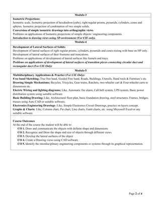
• CIE component should comprise of Continuous evaluation of Drawing work of students as and when the
Modules are covered based onbelow detailed weightage.
Module Max. Marks
Weightage
Evaluation Weightage in marks
Computer display and print out
(a)
Sketching
(b)
Module 1 15 10 05
Module 2 20 15 05
Module 3 20 20 00
Module 4 20 20 00
Module 5 25 15 10
Total 100 80 20
Consideration of Class work Total of [(a) + (b)] = 100
Scaled down to 30 Marks
• At least one Test covering all the modules is to be conducted for 100 marks and evaluation to be based SEE
pattern, and the same is to be scaled down to 20Marks.
• The final CIE = Class work marks + Test marks
Semester End Examination (SEE)
• SEE shall be conducted and evaluated for maximum marks 100. Marks obtained shall be accounted for SEE
final marks, reducing it by 50%
• Question paper shall be set jointly by both Internal and External Examiner and made available for each batch as
per schedule. Questions are to be set preferably from Text Books.
• Related to Module-1: One full question can be set either from “points & lines” or “planes”.
• Evaluation shall be carried jointly by both the examiners.
• Scheme of Evaluation: To be defined by the examiners jointly and the same shall be submitted to the university
along with question paper.
• One full question shall be set from each of the Module from Modules 1,2,3 and 4 as per the below tabled
weightage details. However, the student may be awarded full marks, if he/she completes solution on
computer display without sketch.
4. Page 4 of 4
Module Max. Marks
Weightage
Evaluation Weightage in marks
Computer display and print out
(a)
Preparatory sketching
(b)
Module 1 20 15 05
Module 2 30 25 05
Module 3 25 20 05
Module 4 25 20 05
Total 100 80 20
Consideration of SEE Marks Total of (a) + (b) ÷ 2 = Final SEE marks
Suggested Learning Resources:
Text Books
• S.N. Lal, & T Madhusudhan:, Engineering Visulisation, 1st
Edition, Cengage,Publication
• Parthasarathy N. S., Vela Murali, Engineering Drawing, Oxford University Press, 2015.
Reference Books
• Bhattacharya S. K., Electrical Engineering Drawing, New Age International publishers, second edition 1998,
reprint 2005.
• Chris Schroder, Printed Circuit Board Design using AutoCAD, Newnes, 1997.
• K S Sai Ram Design of steel structures, , Third Edition by Pearson
• Nainan p kurian Design of foundation systems, Narosa publications
• A S Pabla, Electrical power distribution, 6th edition, Tata Mcgraw hill
• Bhatt, N.D., Engineering Drawing: Plane and Solid Geometry, 53rd
edition, Charotar Publishing House Pvt.
Limited, 2019.
• K. R. Gopalakrishna, & Sudhir Gopalakrishna: Textbook Of Computer Aided Engineering Drawing, 39th
Edition, Subash Stores, Bangalore, 2017
COs and POs Mapping (CO-PO mappings are only Indicative)
COs POs
1 2 3 4 5 6 7 8 9 10 11 12
CO1 3 2 3 1 1 1 3 2
CO2 3 2 3 1 1 1 3 2
CO3 3 2 3 1 1 1 3 2
CO4 3 3 3 1 1 1 3 1
CO5 3 2 3 1 3 2
Level 3- Highly Mapped, Level 2-Moderately Mapped, Level 1-Low Mapped, Level 0- Not Mapped