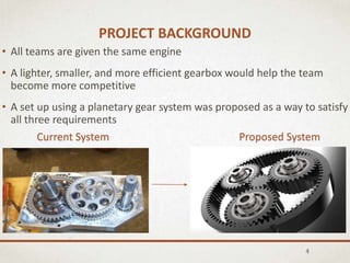
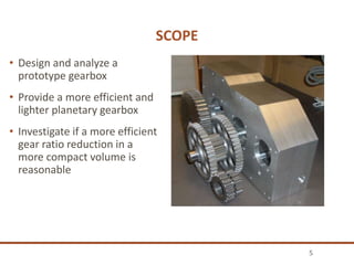
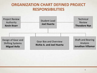
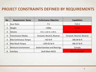
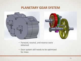
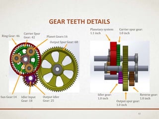
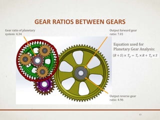
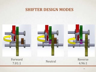
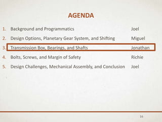
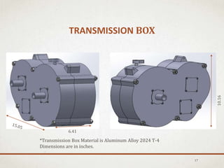
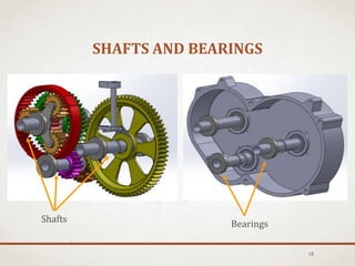
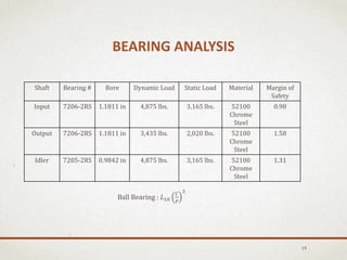
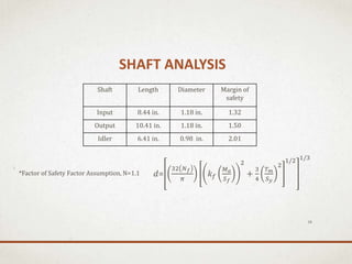
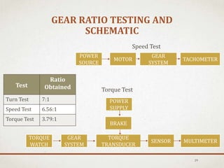
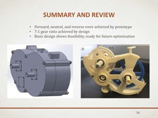
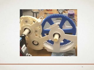
Planetary Gear Transmission
Final Presentation
May 27, 2016
Team Members: Joel Huerta
Miguel Avila
Jonathan Villamor
Richie Aunchareonpornpat
SAE BAJA Liaison: Kevin Knarr
Faculty Advisor: Ted Nye
California State University, Los Angeles
AGENDA
2
1. Background and Programmatics Joel
2. Design Options, Planetary Gear System, and Shifting Miguel
3. Transmission Box, Bearings, and Shafts Jonathan
4. Bolts, Screws, and Margin of Safety Richie
5. Design Challenges, Mechanical Assembly, and Conclusion Joel
WHAT IS BAJA?
• Annual Competition
by Society of
Automotive Engineers
• Small off-road cars
that can withstand
harsh terrain
• Judged based on
various events (Hill
Climbs, Rock Crawls,
Endurance Race, etc.)
3
PROJECT BACKGROUND
• All teams are given the same engine
• A lighter, smaller, and more efficient gearbox would help the team
become more competitive
• A set up using a planetary gear system was proposed as a way to satisfy
all three requirements
4
Current System Proposed System
SCOPE
• Design and analyze a
prototype gearbox
• Provide a more efficient and
lighter planetary gearbox
• Investigate if a more efficient
gear ratio reduction in a
more compact volume is
reasonable
5
ORGANIZATION CHART DEFINED PROJECT
RESPONSIBILITIES
6
Student Lead
Joel Huerta
Technical
Review
Theodore Nye
Project Review
Authority
Kevin Knarr
Design of Gear and
Shifting Systems
Miguel Avila
Gear Box and Overview
Richie A. and Joel Huerta
Shaft and Bearing
Analysis
Jonathan Villamor
PROJECT CONSTRAINTS WERE MET
WITH SCHEDULE
7
WBS 4 11 18 25 1 8 15 22 29 6 13 20 27 3 10 17 24 31 7 14 21 28 6 13 20 27 3 10 17 24 1 8 15 22 29 5 12 19 26
1 ProgramMilestons SRR/CoDR PDR Deliver CDR/Expo
1.1 ProgramKeyEvents OrderParts Receive Parts Baja Competition
1.2 Phase 1-Requirements andConcept Design
1.3 TransmissionRequirements
1.4 Reviews
2 Phase 2-Detail DesignandFabrication
2.1 Designof Transmission
2.2 Analysis of Transmission
2.3 Concept Designof TransmissionBox
Select Appropriate Shaft Lengths and Diameters
2.4 Stress and LoadingAnalysis of Gears
2.5 Stress and LoadingAnalysis of Shafts and Sizingof Bearings
2.6 Designof Prototype
3 Phase 3-Final AssemblyandEvaluation
3.1 Fabricationof Prototype
3.2 Assemblyof Gear Box
3.3 Testingof Gear Box
3.4 Evaluationof Output Gear Ratio
3.5 Failure Modes and Effects Analysis
4 ProgramManagement
4.1 WeeklyMeetings Agendas and Minutes
4.2 OralPresentationand WrittenReport
4.3 Reviews
Nov
FallQuarter2015
Dec Jan
Activity
Apr May JuneOct
WinterQuarter2016 SpringQuarter2016
MarFeb
PROJECT CONSTRAINTS DEFINED BY REQUIREMENTS
8
No. Requirement Name Performance Objective Capabilities
1 Gear Ratio 7:1 7.01:1
2 Weight <39lbs 51 lbs
3 Volume 4 in. x 12 in. x 8 in. 6.41 in.x 15.05 in. x 10.16 in.
4 Transmission Modes Forward, Neutral, Reverse Forward, Neutral, Reverse
5 Max Continuous Torque >42 lb-ft 180.28 lb-ft
6 Max Shock Torque >293.02 lb-ft 306.37 lb-ft
7 Moisture Environment Sealed Gearbox and Bearings Comply
8 Interface Shall Meet MICD Non Compliant
AGENDA
9
1. Background and Programmatics Joel
2. Design Options, Planetary Gear System, and Shifting Miguel
3. Transmission Box, Bearings, and Shafts Jonathan
4. Bolts, Screws, and Margin of Safety Richie
5. Design Challenges, Mechanical Assembly, and Conclusion Joel
CONCEPT DESIGN OPTIONS
10
Design 2Design 1 Design 3
• Most Efficient
• Heaviest Design
• Hard to achieve reverse
• Expensive Ring Gear
• Lightest Design
• Spur Gears Easy to Design
PLANETARY GEAR SYSTEM
• Forward, neutral, and reverse were
obtained
• Gear system still needs to be optimized
for mass
11
GEAR TEETH DETAILS
12
Output Spur Gear: 68
Ring Gear: 46 Planet Gears:16
Sun Gear:14
Carrier Spur
Gear: 42
Idler Input
Gear: 18
Output Idler
Gear: 25 Output spur gear:
1.0 inch
Planetary system:
1.1 inch
Idler gear:
1.0 inch
Carrier spur gear:
1.0 inch
Reverse gear:
1.0 inch
GEAR RATIOS BETWEEN GEARS
13
Output forward gear
ratio: 7.01
Output reverse gear
ratio: 4.96
Gear ratio of planetary
system: 4.34
Equation used for
Planetary Gear Analysis:
SHIFTER DESIGN MODES
14
Forward
7.01:1
Neutral
Reverse
4.96:1
SHIFTER DESIGN
15
AGENDA
16
1. Background and Programmatics Joel
2. Design Options, Planetary Gear System, and Shifting Miguel
3. Transmission Box, Bearings, and Shafts Jonathan
4. Bolts, Screws, and Margin of Safety Richie
5. Design Challenges, Mechanical Assembly, and Conclusion Joel
TRANSMISSION BOX
17
*Transmission Box Material is Aluminum Alloy 2024 T-4
Dimensions are in inches.
6.41
10.16
SHAFTS AND BEARINGS
18
BearingsShafts
19
Shaft Bearing # Bore Dynamic Load Static Load Material Margin of
Safety
Input 7206-2RS 1.1811 in 4,875 lbs. 3,165 lbs. 52100
Chrome
Steel
0.98
Output 7206-2RS 1.1811 in 3,435 lbs. 2,020 lbs. 52100
Chrome
Steel
1.58
Idler 7205-2RS 0.9842 in 4,875 lbs. 3,165 lbs. 52100
Chrome
Steel
1.31
BEARING ANALYSIS
Ball Bearing : 𝐿10
𝐶
𝑃
3
SHAFT ANALYSIS
20
Shaft Length Diameter Margin of
safety
Input 8.44 in. 1.18 in. 1.32
Output 10.41 in. 1.18 in. 1.50
Idler 6.41 in. 0.98 in. 2.01
𝑑=
32 𝑁 𝑓
𝜋
𝑘 𝑓
𝑀 𝑎
𝑆 𝑓
2
+
3
4
𝑇 𝑚
𝑆 𝑦
2
1/2 1/3
*Factor of Safety Factor Assumption, N=1.1
AGENDA
21
1. Background and Programmatics Joel
2. Design Options, Planetary Gear System, and Shifting Miguel
3. Transmission Box, Bearings, and Shafts Jonathan
4. Bolts, Screws, and Margin of Safety Richie
5. Design Challenges, Mechanical Assembly, and Conclusion Joel
BOLTS AND SCREWS
22
Bolts Screws
MARGIN OF SAFETY TABLE
Face
Width
Number
of Teeth
Bending
Stress
Margin of
Safety
Gear F (in) N σb (psi) Bending
Sun 1.1 14 74749.15 0.37
Planet 1.1 16 76410.24 0.34
Ring 1.1 46 44082.83 1.32
Carrier 1 42 83913.81 0.22
Idler 1 18 25923.03 2.94
Reverse 1 25 81228.26 0.26
Output 1 68 94766.31 0.08
Margin of Safety:
𝑀𝑆 =
𝜎 𝑦
𝜎 𝑝𝑟𝑒𝑑
′
∗ 𝑁
− 1
*Factor of Safety Factor
Assumption, N=1.1
Bending Endurance Strength (SFB)=112400 psi
OLD VS. NEW
24
AGENDA
25
1. Background and Programmatics Joel
2. Design Options, Planetary Gear System, and Shifting Miguel
3. Transmission Box, Bearings, and Shafts Jonathan
4. Bolts, Screws, and Margin of Safety Richie
5. Design Challenges, Mechanical Assembly, and Conclusion Joel
DESIGN CHALLENGES
26
Fixed Clutch and U-Joint Distance
6.41 inches
Volume Requires Frame
Modifications
(Old Design)
PRINTED GEARBOX
27
11.81 in.
3D PRINTED GEARBOX
28
GEAR RATIO TESTING AND
SCHEMATIC
Test
Ratio
Obtained
Turn Test 7:1
Speed Test 6.56:1
Torque Test 3.79:1
29
Speed Test
POWER
SOURCE
MOTOR
GEAR
SYSTEM
TACHOMETER
BRAKE
GEAR
SYSTEM
TORQUE
WATCH
SENSOR
TORQUE
TRANSDUCER
MULTIMETER
POWER
SUPPLY
Torque Test
SUMMARY AND REVIEW
30
• Forward, neutral, and reverse were achieved by prototype
• 7:1 gear ratio achieved by design
• Basic design shows feasibility, ready for future optimization
31
QUESTIONS?

Senior Design Presentation Spring 2016

  • 1.
    Planetary Gear Transmission FinalPresentation May 27, 2016 Team Members: Joel Huerta Miguel Avila Jonathan Villamor Richie Aunchareonpornpat SAE BAJA Liaison: Kevin Knarr Faculty Advisor: Ted Nye California State University, Los Angeles
  • 2.
    AGENDA 2 1. Background andProgrammatics Joel 2. Design Options, Planetary Gear System, and Shifting Miguel 3. Transmission Box, Bearings, and Shafts Jonathan 4. Bolts, Screws, and Margin of Safety Richie 5. Design Challenges, Mechanical Assembly, and Conclusion Joel
  • 3.
    WHAT IS BAJA? •Annual Competition by Society of Automotive Engineers • Small off-road cars that can withstand harsh terrain • Judged based on various events (Hill Climbs, Rock Crawls, Endurance Race, etc.) 3
  • 4.
    PROJECT BACKGROUND • Allteams are given the same engine • A lighter, smaller, and more efficient gearbox would help the team become more competitive • A set up using a planetary gear system was proposed as a way to satisfy all three requirements 4 Current System Proposed System
  • 5.
    SCOPE • Design andanalyze a prototype gearbox • Provide a more efficient and lighter planetary gearbox • Investigate if a more efficient gear ratio reduction in a more compact volume is reasonable 5
  • 6.
    ORGANIZATION CHART DEFINEDPROJECT RESPONSIBILITIES 6 Student Lead Joel Huerta Technical Review Theodore Nye Project Review Authority Kevin Knarr Design of Gear and Shifting Systems Miguel Avila Gear Box and Overview Richie A. and Joel Huerta Shaft and Bearing Analysis Jonathan Villamor
  • 7.
    PROJECT CONSTRAINTS WEREMET WITH SCHEDULE 7 WBS 4 11 18 25 1 8 15 22 29 6 13 20 27 3 10 17 24 31 7 14 21 28 6 13 20 27 3 10 17 24 1 8 15 22 29 5 12 19 26 1 ProgramMilestons SRR/CoDR PDR Deliver CDR/Expo 1.1 ProgramKeyEvents OrderParts Receive Parts Baja Competition 1.2 Phase 1-Requirements andConcept Design 1.3 TransmissionRequirements 1.4 Reviews 2 Phase 2-Detail DesignandFabrication 2.1 Designof Transmission 2.2 Analysis of Transmission 2.3 Concept Designof TransmissionBox Select Appropriate Shaft Lengths and Diameters 2.4 Stress and LoadingAnalysis of Gears 2.5 Stress and LoadingAnalysis of Shafts and Sizingof Bearings 2.6 Designof Prototype 3 Phase 3-Final AssemblyandEvaluation 3.1 Fabricationof Prototype 3.2 Assemblyof Gear Box 3.3 Testingof Gear Box 3.4 Evaluationof Output Gear Ratio 3.5 Failure Modes and Effects Analysis 4 ProgramManagement 4.1 WeeklyMeetings Agendas and Minutes 4.2 OralPresentationand WrittenReport 4.3 Reviews Nov FallQuarter2015 Dec Jan Activity Apr May JuneOct WinterQuarter2016 SpringQuarter2016 MarFeb
  • 8.
    PROJECT CONSTRAINTS DEFINEDBY REQUIREMENTS 8 No. Requirement Name Performance Objective Capabilities 1 Gear Ratio 7:1 7.01:1 2 Weight <39lbs 51 lbs 3 Volume 4 in. x 12 in. x 8 in. 6.41 in.x 15.05 in. x 10.16 in. 4 Transmission Modes Forward, Neutral, Reverse Forward, Neutral, Reverse 5 Max Continuous Torque >42 lb-ft 180.28 lb-ft 6 Max Shock Torque >293.02 lb-ft 306.37 lb-ft 7 Moisture Environment Sealed Gearbox and Bearings Comply 8 Interface Shall Meet MICD Non Compliant
  • 9.
    AGENDA 9 1. Background andProgrammatics Joel 2. Design Options, Planetary Gear System, and Shifting Miguel 3. Transmission Box, Bearings, and Shafts Jonathan 4. Bolts, Screws, and Margin of Safety Richie 5. Design Challenges, Mechanical Assembly, and Conclusion Joel
  • 10.
    CONCEPT DESIGN OPTIONS 10 Design2Design 1 Design 3 • Most Efficient • Heaviest Design • Hard to achieve reverse • Expensive Ring Gear • Lightest Design • Spur Gears Easy to Design
  • 11.
    PLANETARY GEAR SYSTEM •Forward, neutral, and reverse were obtained • Gear system still needs to be optimized for mass 11
  • 12.
    GEAR TEETH DETAILS 12 OutputSpur Gear: 68 Ring Gear: 46 Planet Gears:16 Sun Gear:14 Carrier Spur Gear: 42 Idler Input Gear: 18 Output Idler Gear: 25 Output spur gear: 1.0 inch Planetary system: 1.1 inch Idler gear: 1.0 inch Carrier spur gear: 1.0 inch Reverse gear: 1.0 inch
  • 13.
    GEAR RATIOS BETWEENGEARS 13 Output forward gear ratio: 7.01 Output reverse gear ratio: 4.96 Gear ratio of planetary system: 4.34 Equation used for Planetary Gear Analysis:
  • 14.
  • 15.
  • 16.
    AGENDA 16 1. Background andProgrammatics Joel 2. Design Options, Planetary Gear System, and Shifting Miguel 3. Transmission Box, Bearings, and Shafts Jonathan 4. Bolts, Screws, and Margin of Safety Richie 5. Design Challenges, Mechanical Assembly, and Conclusion Joel
  • 17.
    TRANSMISSION BOX 17 *Transmission BoxMaterial is Aluminum Alloy 2024 T-4 Dimensions are in inches. 6.41 10.16
  • 18.
  • 19.
    19 Shaft Bearing #Bore Dynamic Load Static Load Material Margin of Safety Input 7206-2RS 1.1811 in 4,875 lbs. 3,165 lbs. 52100 Chrome Steel 0.98 Output 7206-2RS 1.1811 in 3,435 lbs. 2,020 lbs. 52100 Chrome Steel 1.58 Idler 7205-2RS 0.9842 in 4,875 lbs. 3,165 lbs. 52100 Chrome Steel 1.31 BEARING ANALYSIS Ball Bearing : 𝐿10 𝐶 𝑃 3
  • 20.
    SHAFT ANALYSIS 20 Shaft LengthDiameter Margin of safety Input 8.44 in. 1.18 in. 1.32 Output 10.41 in. 1.18 in. 1.50 Idler 6.41 in. 0.98 in. 2.01 𝑑= 32 𝑁 𝑓 𝜋 𝑘 𝑓 𝑀 𝑎 𝑆 𝑓 2 + 3 4 𝑇 𝑚 𝑆 𝑦 2 1/2 1/3 *Factor of Safety Factor Assumption, N=1.1
  • 21.
    AGENDA 21 1. Background andProgrammatics Joel 2. Design Options, Planetary Gear System, and Shifting Miguel 3. Transmission Box, Bearings, and Shafts Jonathan 4. Bolts, Screws, and Margin of Safety Richie 5. Design Challenges, Mechanical Assembly, and Conclusion Joel
  • 22.
  • 23.
    MARGIN OF SAFETYTABLE Face Width Number of Teeth Bending Stress Margin of Safety Gear F (in) N σb (psi) Bending Sun 1.1 14 74749.15 0.37 Planet 1.1 16 76410.24 0.34 Ring 1.1 46 44082.83 1.32 Carrier 1 42 83913.81 0.22 Idler 1 18 25923.03 2.94 Reverse 1 25 81228.26 0.26 Output 1 68 94766.31 0.08 Margin of Safety: 𝑀𝑆 = 𝜎 𝑦 𝜎 𝑝𝑟𝑒𝑑 ′ ∗ 𝑁 − 1 *Factor of Safety Factor Assumption, N=1.1 Bending Endurance Strength (SFB)=112400 psi
  • 24.
  • 25.
    AGENDA 25 1. Background andProgrammatics Joel 2. Design Options, Planetary Gear System, and Shifting Miguel 3. Transmission Box, Bearings, and Shafts Jonathan 4. Bolts, Screws, and Margin of Safety Richie 5. Design Challenges, Mechanical Assembly, and Conclusion Joel
  • 26.
    DESIGN CHALLENGES 26 Fixed Clutchand U-Joint Distance 6.41 inches Volume Requires Frame Modifications (Old Design)
  • 27.
  • 28.
  • 29.
    GEAR RATIO TESTINGAND SCHEMATIC Test Ratio Obtained Turn Test 7:1 Speed Test 6.56:1 Torque Test 3.79:1 29 Speed Test POWER SOURCE MOTOR GEAR SYSTEM TACHOMETER BRAKE GEAR SYSTEM TORQUE WATCH SENSOR TORQUE TRANSDUCER MULTIMETER POWER SUPPLY Torque Test
  • 30.
    SUMMARY AND REVIEW 30 •Forward, neutral, and reverse were achieved by prototype • 7:1 gear ratio achieved by design • Basic design shows feasibility, ready for future optimization
  • 31.
  • 32.

Editor's Notes

  • #6 Mention why scope changed.
  • #9 Update Mass Capability
  • #12 Check the optimization for mass part