Download as PDF, PPTX

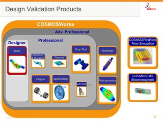
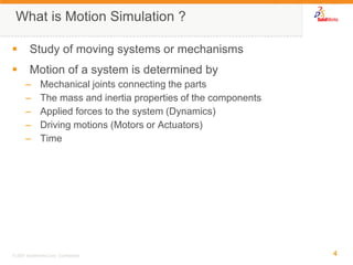
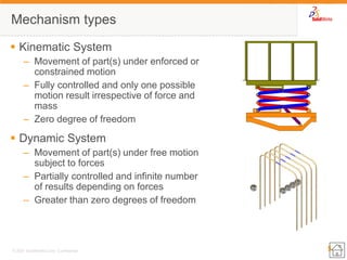
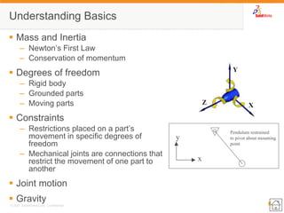
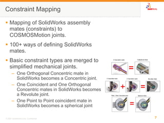

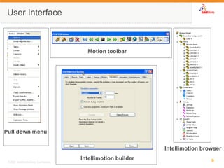
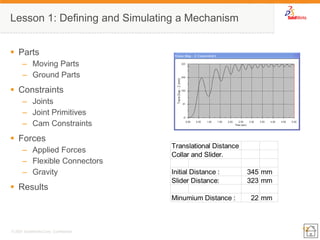
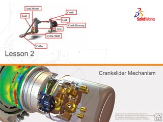
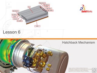
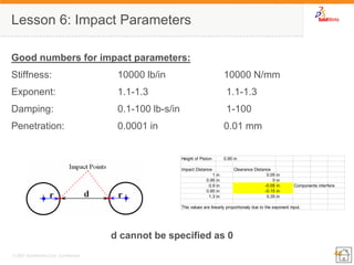
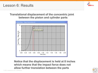
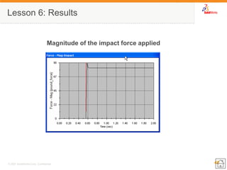
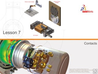
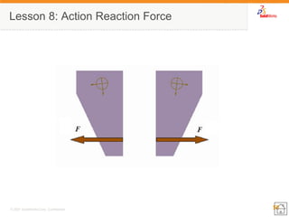
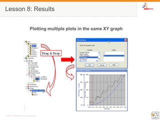
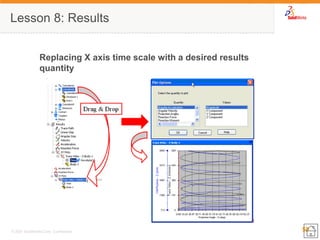
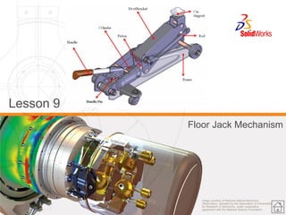
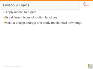

This document provides an overview of a COSMOSMotion Essentials Training course. The course covers topics like basic mechanism types, joints, forces, springs, dampers and contacts. It includes 8 lessons on simulating mechanisms like a governor, crankslider, piston mechanism and more. Advanced topics covered are attaching parts, modifying material properties, applying action-only and impact forces, and advanced plotting techniques in COSMOSMotion. The document outlines the topics, concepts and results covered in each lesson.


