Download to read offline


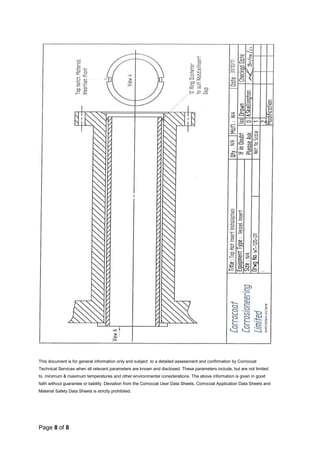

The document outlines the manufacturing and installation process for Corrocoat CCL top hat nozzle inserts, which are designed for applications where conventional coating methods are not suitable. It specifies the necessary materials, safety precautions, surface preparation, and detailed installation procedures, including integrity checks and handling guidelines. The inserts are customizable and must be handled and installed with care to ensure effectiveness and safety.


![Rtfi weld defects[1]](https://cdn.slidesharecdn.com/ss_thumbnails/rtfiwelddefects1-190507184037-thumbnail.jpg?width=640&height=640&fit=bounds)


