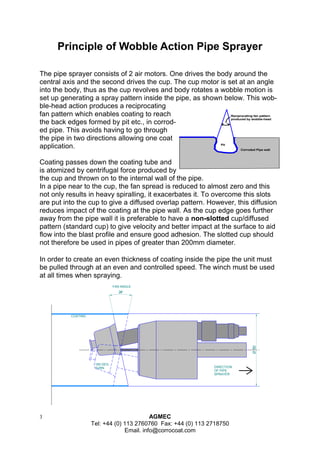
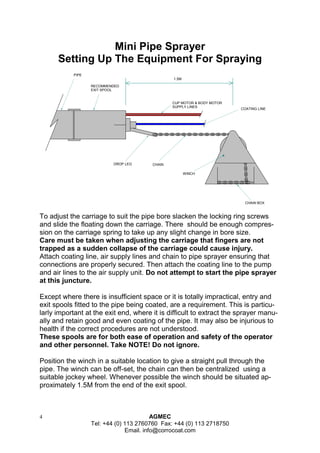
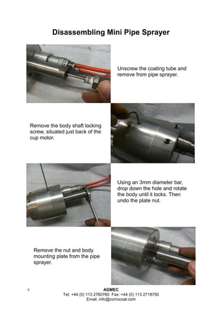
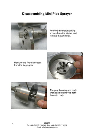
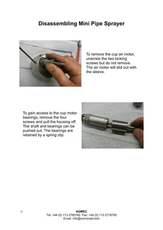
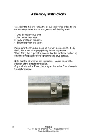
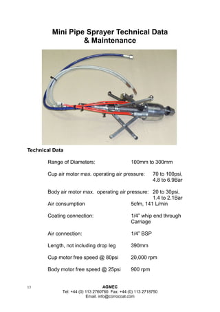
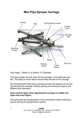
1 AGMEC 
Tel: +44 (0) 113 2760760 Fax: +44 (0) 113 2718750 
Email. info@corrocoat.com 
Operation and 
Maintenance 
Manual 
AGMEC 
A 
Division of Corrocoat Corrosioneering 
MPS 
(Mini Pipe Sprayer) 
Contact: 
Tel. +44 113 2 760 760 
Fax. +44 113 2 718 750 
Email. info@corrocoat.com 
Technical Services 02/01/2013 
4” (100mm) NB To 12” (300mm) NB Pipe
2 AGMEC 
Tel: +44 (0) 113 2760760 Fax: +44 (0) 113 2718750 
Email. info@corrocoat.com 
Mini Pipe Sprayer 
Operations and Maintenance manual 
Index 
Page 
Principle of wobble action pipe sprayer 3 
Setting Up The Equipment For Spraying 4 & 5 
Calculation of winch speed & Flow 6 & 7 
Disassembly of pipe sprayer 8, 9, 10 & 11 
Assembly Instructions 12 
Technical data and maintenance 13 & 14 
Pipe sprayer carriage 15
3 AGMEC 
Tel: +44 (0) 113 2760760 Fax: +44 (0) 113 2718750 
Email. info@corrocoat.com 
24° 
Ø 100 
FAN ANGLE 
COATING 
180 DEG. 
TURN DIRECTION 
OF PIPE 
SPRAYER 
Principle of Wobble Action Pipe Sprayer 
The pipe sprayer consists of 2 air motors. One drives the body around the 
central axis and the second drives the cup. The cup motor is set at an angle 
into the body, thus as the cup revolves and body rotates a wobble motion is 
set up generating a spray pattern inside the pipe, as shown below. This wob-ble- 
head action produces a reciprocating 
fan pattern which enables coating to reach 
the back edges formed by pit etc., in corrod-ed 
pipe. This avoids having to go through 
the pipe in two directions allowing one coat 
application. 
Coating passes down the coating tube and 
is atomized by centrifugal force produced by 
the cup and thrown on to the internal wall of the pipe. 
In a pipe near to the cup, the fan spread is reduced to almost zero and this 
not only results in heavy spiralling, it exacerbates it. To overcome this slots 
are put into the cup to give a diffused overlap pattern. However, this diffusion 
reduces impact of the coating at the pipe wall. As the cup edge goes further 
away from the pipe wall it is preferable to have a non-slotted cup/diffused 
pattern (standard cup) to give velocity and better impact at the surface to aid 
flow into the blast profile and ensure good adhesion. The slotted cup should 
not therefore be used in pipes of greater than 200mm diameter. 
In order to create an even thickness of coating inside the pipe the unit must 
be pulled through at an even and controlled speed. The winch must be used 
at all times when spraying. 
Corroded Pipe wall 
Pit 
Reciprocating fan pattern 
produced by wobble-head
4 AGMEC 
Tel: +44 (0) 113 2760760 Fax: +44 (0) 113 2718750 
Email. info@corrocoat.com 
Mini Pipe Sprayer 
Setting Up The Equipment For Spraying 
To adjust the carriage to suit the pipe bore slacken the locking ring screws and slide the floating down the carriage. There should be enough compres- sion on the carriage spring to take up any slight change in bore size. 
Care must be taken when adjusting the carriage that fingers are not trapped as a sudden collapse of the carriage could cause injury. 
Attach coating line, air supply lines and chain to pipe sprayer ensuring that connections are properly secured. Then attach the coating line to the pump and air lines to the air supply unit. Do not attempt to start the pipe sprayer at this juncture. 
Except where there is insufficient space or it is totally impractical, entry and exit spools fitted to the pipe being coated, are a requirement. This is particu- larly important at the exit end, where it is difficult to extract the sprayer manu- ally and retain good and even coating of the pipe. It may also be injurious to health if the correct procedures are not understood. 
These spools are for both ease of operation and safety of the operator and other personnel. Take NOTE! Do not ignore. 
Position the winch in a suitable location to give a straight pull through the pipe. The winch can be off-set, the chain can then be centralized using a suitable jockey wheel. Whenever possible the winch should be situated ap- proximately 1.5M from the end of the exit spool. 
RECOMMENDEDEXIT SPOOLPIPECUP MOTOR & BODY MOTORSUPPLY LINESCOATING LINECHAINWINCHCHAIN BOX1.5MDROP LEG
5 AGMEC 
Tel: +44 (0) 113 2760760 Fax: +44 (0) 113 2718750 
Email. info@corrocoat.com 
Mini Pipe Sprayer 
Setting Up The Equipment For Spraying 
The winch should be mounted by bolting or clamping to a secure and firm surface, bearing in mind the pulling loads required. Ample clear- ance must be given to provide free fall of the chain. 
The pipe sprayer should be pushed or pulled through the work-piece using a suitable line or push rods and chain connected to the winch. 
The drop leg should be adjusted to prevent the chain from sagging dur- ing a run. 
The winch guard should be installed. It should be borne in mind that when operating the winch, fingers and items of loose clothing should be kept well clear of the entry to the winch. 
Before operating the equipment suitable protective clothing, gog- gles and face mask should be worn. 
Coating exits the rotating cup at high velocity and injury can be caused where this is directed to the skin. Care should be taken to ensure that coating does not exit the rotating cup without the unit in an entry spool or other suitable guard. This applies as aforementioned at the exit as well. 
When cleaning or setting up the flow rate it will be necessary to remove the cup. 
The cup puller must be used to 
remove the cup at all times.
6 AGMEC 
Tel: +44 (0) 113 2760760 Fax: +44 (0) 113 2718750 
Email. info@corrocoat.com 
Mini Pipe Sprayer 
Winch speed settings 
During this operation the operator must be wearing goggles, face mask and 
suitable clothing as initially until air is purged from the coating line, splutter 
will occur. 
It should be noted that delivery rates should not be checked until this splutter has 
ceased. 
Coating 
Flow Rate 
Ltr/min. 
Pipe Diameter in mm 
0.5 
0.75 
1.00 
100 
7.0 
10.4 
13.9 
4.6 
7.0 
9.3 
3.5 
5.2 
7.0 
2.8 
4.2 
5.6 
2.3 
3.5 
4.6 
150 200 250 300 
Winch Speed in 
Ft/min. 
The linear speed of the pipe sprayer will be dependant upon the amount of coating 
fed into the unit for a given pipe diameter. It is therefore possible to have a low line-ar 
speed with a low coating flow rate, or high linear speed with a high coating flow 
rate. 
To obtain spiral free coating it may be necessary to operate at slow linear speeds. 
This table is based 
on a coating thick-ness 
of 0.75mm. Set 
the pump output to 
one of the three flow 
rates shown, then 
read off the winch 
speed according to 
pipe diameter. 
With the cup removed, pump the coating to the pipe sprayer at suitable steady flow 
rate. Measure the amount of coating delivered over a one minute period in litres, 
Then using the formula below the theoretical winch speed can be calculated, adjust 
the flow rate and or winch speed to achieve the correct thickness. 
FLOW (Ltr/min) x 1000 
INSIDE DIAMETER OF PIPE (mm) X 3.142 X COATING THICKNESS (mm) 
X 3.28 = WINCH SPEED (Ft/min.) 
If your parameters are outside the table then the calculation below can be used to 
find the theoretical winch speed. 
Coating 
Flow Rate 
Ltr/min. 
Pipe Diameter in mm 
Winch Speed in 
Ft/min. 
This table is to be 
used to record 
actual readings 
taken. 
Note which type of 
coating was used.
7 AGMEC 
Tel: +44 (0) 113 2760760 Fax: +44 (0) 113 2718750 
Email. info@corrocoat.com 
Mini Pipe Sprayer 
Calculation of Winch Speed/Flow 
It should be borne in mind that this procedure is an approximation of what will be required to achieve a given wet film thickness. To Obtain an approximate dry film thickness the wet film thickness should be divided by 1.23. This figure will vary substantially dependent upon blast profile, surface and cure conditions. 
Once the unit has been set up, start the pipe sprayer air motors and let them run up to speed. 
WARNING: Keep hands well away from the cup and body when rotating. The pipe sprayer must only be run up inside the entry spool piece or suitable alternative. Ensure that the guard is over the winch pulleys before commencing operation. 
Start the pump and winch at the same time. Once complete check the coating thickness and adjust the material flow or winch speed as necessary to achieve the desired thickness. 
If several coats are being applied it is possible for under or over thickness to be corrected on subsequent layers. 
Where accurate thickness is necessary on the first layer, then it is suggested that the equipment be set up in a short length of dummy pipe. 
As the pipe sprayer is due to exit the pipe the coating feed pump , winch and air motors should be turned off in that order. However, where the exit spool is not used it will be necessary to guide the unit out of the pipe before turning the unit off. A pipe spool should be used wherever possible. 
Extreme care should be taken to ensure that hands are kept well clear of the winch chain entry points and that the pump is turned off immediately the unit exits the pipe. This will necessitate 2 
operators with the correct safety equipment.
8 AGMEC 
Tel: +44 (0) 113 2760760 Fax: +44 (0) 113 2718750 
Email. info@corrocoat.com 
Disassembling Mini Pipe Sprayer 
Cup 
Cup 
Motor Body Body 
Motor 
Motor 
Plate 
Nut 
Coating 
Tube 
General view showing location of air motors, gears, bearings and seals. 
The following pages show the detailed instructions to disassemble the 
unit.
9 AGMEC 
Tel: +44 (0) 113 2760760 Fax: +44 (0) 113 2718750 
Email. info@corrocoat.com 
Disassembling Mini Pipe Sprayer 
Unscrew the coating tube and remove from pipe sprayer. 
Remove the body shaft locking screw, situated just back of the cup motor. 
Using an 3mm diameter bar, drop down the hole and rotate the body until it locks. Then undo the plate nut. 
Remove the nut and body mounting plate from the pipe sprayer.
10 AGMEC 
Tel: +44 (0) 113 2760760 Fax: +44 (0) 113 2718750 
Email. info@corrocoat.com 
Disassembling Mini Pipe Sprayer 
Remove the motor locking screws from the sleeve and remove the air motor. 
Remove the four cap heads from the large gear 
The gear housing and body shaft can be removed from the main body.
11 AGMEC 
Tel: +44 (0) 113 2760760 Fax: +44 (0) 113 2718750 
Email. info@corrocoat.com 
Disassembling Mini Pipe Sprayer 
To remove the cup air motor, unscrew the two locking screws but do not remove. The air motor will slid out with the sleeve. 
To gain access to the cup motor bearings, remove the four screws and pull the housing off. 
The shaft and bearings can be pushed out. The bearings are retained by a spring clip.
12 AGMEC 
Tel: +44 (0) 113 2760760 Fax: +44 (0) 113 2718750 
Email. info@corrocoat.com 
To assemble the unit follow the above in reverse order, taking care to keep clean and to add grease to following parts: 
1. Cup air motor drive end. 
2. Cup motor bearings. 
3. Body shaft and bearings. 
4. Silicone grease the gears. 
Make sure the 3mm bar goes all the way down into the body shaft, this is the air supply porting for the cup motor. 
When fitting the cup motor, ensure that the motor is pushed up onto the o ring seal before tightening the grub screws. 
Note that the air motors are reversible , please ensure the position of the direction indicator. 
Cup motor is set at R and the body motor set at F as shown in the picture below. 
Assembly Instructions
13 AGMEC 
Tel: +44 (0) 113 2760760 Fax: +44 (0) 113 2718750 
Email. info@corrocoat.com 
Mini Pipe Sprayer Technical Data 
& Maintenance 
Technical Data 
Range of Diameters: 100mm to 300mm 
Cup air motor max. operating air pressure: 70 to 100psi, 4.8 to 6.9Bar 
Body air motor max. operating air pressure: 20 to 30psi, 1.4 to 2.1Bar 
Air consumption 5cfm, 141 L/min 
Coating connection: 1/4” whip end through 
Carriage 
Air connection: 1/4” BSP 
Length, not including drop leg 390mm 
Cup motor free speed @ 80psi 20,000 rpm 
Body motor free speed @ 25psi 900 rpm
14 AGMEC 
Tel: +44 (0) 113 2760760 Fax: +44 (0) 113 2718750 
Email. info@corrocoat.com 
Maintenance 
When pumping material through line without the cup on keep the shaft covered with tubing or similar. This will facilitate easy fitting of cup. 
Once the unit has completed a run care must be taken when cleaning down, always point the unit down into the solvent when washing. 
Never immerse the pipe sprayer in solvent. 
A couple of drops of oil on the cup shaft , cup shaft end cover and shaft threads. This will make sure the shaft rotates freely and that the cup fits easily before and after each run, wipe away any excess. 
It is essential that air lines are kept clean and are sealed immediately by capping when not in use. They should only be uncapped immediately prior to fitting to the equipment. 
The biggest single cause of failure in this equipment is the ingress of dirt to the air motors — proper care and attention will avoid this. 
If the air lines are kept clean and no dirt is allowed to enter the air mo- tors, the air motors are correctly lubricated (not over lubricated) then these motors should not require regular maintenance. 
Mini Pipe Sprayer Technical Data 
& Maintenance
15 AGMEC 
Tel: +44 (0) 113 2760760 Fax: +44 (0) 113 2718750 
Email. info@corrocoat.com 
Wheels 
Legs 
Spring tension screws 
Locking 
screw 
Carriage 
tube 
Drop Leg 
Spring 
Floating 
Sleeve 
Fixed 
Sleeve 
Mounting 
Flange 
Mini Pipe Sprayer Carriage 
Pipe range: 100mm 4” to 300mm 12” Diameter 
The pipe sprayer will only slide into the carriage in one particular posi- tion. The body air motor sleeve should follow the flat on the carriage. 
By unscrewing the fixed sleeve clamping screws the sleeves can be slid up and down the carriage, thereby opening and closing the legs to suit different pipe diameters. 
Care must be taken when adjusting the carriage as sudden col- lapse may trap fingers. 
The spring can be pre-adjusted to a set compression before entering a pipe by turning the spring tension screws.

Mini Pipe Sprayer

  • 1.
    1 AGMEC Tel:+44 (0) 113 2760760 Fax: +44 (0) 113 2718750 Email. info@corrocoat.com Operation and Maintenance Manual AGMEC A Division of Corrocoat Corrosioneering MPS (Mini Pipe Sprayer) Contact: Tel. +44 113 2 760 760 Fax. +44 113 2 718 750 Email. info@corrocoat.com Technical Services 02/01/2013 4” (100mm) NB To 12” (300mm) NB Pipe
  • 2.
    2 AGMEC Tel:+44 (0) 113 2760760 Fax: +44 (0) 113 2718750 Email. info@corrocoat.com Mini Pipe Sprayer Operations and Maintenance manual Index Page Principle of wobble action pipe sprayer 3 Setting Up The Equipment For Spraying 4 & 5 Calculation of winch speed & Flow 6 & 7 Disassembly of pipe sprayer 8, 9, 10 & 11 Assembly Instructions 12 Technical data and maintenance 13 & 14 Pipe sprayer carriage 15
  • 3.
    3 AGMEC Tel:+44 (0) 113 2760760 Fax: +44 (0) 113 2718750 Email. info@corrocoat.com 24° Ø 100 FAN ANGLE COATING 180 DEG. TURN DIRECTION OF PIPE SPRAYER Principle of Wobble Action Pipe Sprayer The pipe sprayer consists of 2 air motors. One drives the body around the central axis and the second drives the cup. The cup motor is set at an angle into the body, thus as the cup revolves and body rotates a wobble motion is set up generating a spray pattern inside the pipe, as shown below. This wob-ble- head action produces a reciprocating fan pattern which enables coating to reach the back edges formed by pit etc., in corrod-ed pipe. This avoids having to go through the pipe in two directions allowing one coat application. Coating passes down the coating tube and is atomized by centrifugal force produced by the cup and thrown on to the internal wall of the pipe. In a pipe near to the cup, the fan spread is reduced to almost zero and this not only results in heavy spiralling, it exacerbates it. To overcome this slots are put into the cup to give a diffused overlap pattern. However, this diffusion reduces impact of the coating at the pipe wall. As the cup edge goes further away from the pipe wall it is preferable to have a non-slotted cup/diffused pattern (standard cup) to give velocity and better impact at the surface to aid flow into the blast profile and ensure good adhesion. The slotted cup should not therefore be used in pipes of greater than 200mm diameter. In order to create an even thickness of coating inside the pipe the unit must be pulled through at an even and controlled speed. The winch must be used at all times when spraying. Corroded Pipe wall Pit Reciprocating fan pattern produced by wobble-head
  • 4.
    4 AGMEC Tel:+44 (0) 113 2760760 Fax: +44 (0) 113 2718750 Email. info@corrocoat.com Mini Pipe Sprayer Setting Up The Equipment For Spraying To adjust the carriage to suit the pipe bore slacken the locking ring screws and slide the floating down the carriage. There should be enough compres- sion on the carriage spring to take up any slight change in bore size. Care must be taken when adjusting the carriage that fingers are not trapped as a sudden collapse of the carriage could cause injury. Attach coating line, air supply lines and chain to pipe sprayer ensuring that connections are properly secured. Then attach the coating line to the pump and air lines to the air supply unit. Do not attempt to start the pipe sprayer at this juncture. Except where there is insufficient space or it is totally impractical, entry and exit spools fitted to the pipe being coated, are a requirement. This is particu- larly important at the exit end, where it is difficult to extract the sprayer manu- ally and retain good and even coating of the pipe. It may also be injurious to health if the correct procedures are not understood. These spools are for both ease of operation and safety of the operator and other personnel. Take NOTE! Do not ignore. Position the winch in a suitable location to give a straight pull through the pipe. The winch can be off-set, the chain can then be centralized using a suitable jockey wheel. Whenever possible the winch should be situated ap- proximately 1.5M from the end of the exit spool. RECOMMENDEDEXIT SPOOLPIPECUP MOTOR & BODY MOTORSUPPLY LINESCOATING LINECHAINWINCHCHAIN BOX1.5MDROP LEG
  • 5.
    5 AGMEC Tel:+44 (0) 113 2760760 Fax: +44 (0) 113 2718750 Email. info@corrocoat.com Mini Pipe Sprayer Setting Up The Equipment For Spraying The winch should be mounted by bolting or clamping to a secure and firm surface, bearing in mind the pulling loads required. Ample clear- ance must be given to provide free fall of the chain. The pipe sprayer should be pushed or pulled through the work-piece using a suitable line or push rods and chain connected to the winch. The drop leg should be adjusted to prevent the chain from sagging dur- ing a run. The winch guard should be installed. It should be borne in mind that when operating the winch, fingers and items of loose clothing should be kept well clear of the entry to the winch. Before operating the equipment suitable protective clothing, gog- gles and face mask should be worn. Coating exits the rotating cup at high velocity and injury can be caused where this is directed to the skin. Care should be taken to ensure that coating does not exit the rotating cup without the unit in an entry spool or other suitable guard. This applies as aforementioned at the exit as well. When cleaning or setting up the flow rate it will be necessary to remove the cup. The cup puller must be used to remove the cup at all times.
  • 6.
    6 AGMEC Tel:+44 (0) 113 2760760 Fax: +44 (0) 113 2718750 Email. info@corrocoat.com Mini Pipe Sprayer Winch speed settings During this operation the operator must be wearing goggles, face mask and suitable clothing as initially until air is purged from the coating line, splutter will occur. It should be noted that delivery rates should not be checked until this splutter has ceased. Coating Flow Rate Ltr/min. Pipe Diameter in mm 0.5 0.75 1.00 100 7.0 10.4 13.9 4.6 7.0 9.3 3.5 5.2 7.0 2.8 4.2 5.6 2.3 3.5 4.6 150 200 250 300 Winch Speed in Ft/min. The linear speed of the pipe sprayer will be dependant upon the amount of coating fed into the unit for a given pipe diameter. It is therefore possible to have a low line-ar speed with a low coating flow rate, or high linear speed with a high coating flow rate. To obtain spiral free coating it may be necessary to operate at slow linear speeds. This table is based on a coating thick-ness of 0.75mm. Set the pump output to one of the three flow rates shown, then read off the winch speed according to pipe diameter. With the cup removed, pump the coating to the pipe sprayer at suitable steady flow rate. Measure the amount of coating delivered over a one minute period in litres, Then using the formula below the theoretical winch speed can be calculated, adjust the flow rate and or winch speed to achieve the correct thickness. FLOW (Ltr/min) x 1000 INSIDE DIAMETER OF PIPE (mm) X 3.142 X COATING THICKNESS (mm) X 3.28 = WINCH SPEED (Ft/min.) If your parameters are outside the table then the calculation below can be used to find the theoretical winch speed. Coating Flow Rate Ltr/min. Pipe Diameter in mm Winch Speed in Ft/min. This table is to be used to record actual readings taken. Note which type of coating was used.
  • 7.
    7 AGMEC Tel:+44 (0) 113 2760760 Fax: +44 (0) 113 2718750 Email. info@corrocoat.com Mini Pipe Sprayer Calculation of Winch Speed/Flow It should be borne in mind that this procedure is an approximation of what will be required to achieve a given wet film thickness. To Obtain an approximate dry film thickness the wet film thickness should be divided by 1.23. This figure will vary substantially dependent upon blast profile, surface and cure conditions. Once the unit has been set up, start the pipe sprayer air motors and let them run up to speed. WARNING: Keep hands well away from the cup and body when rotating. The pipe sprayer must only be run up inside the entry spool piece or suitable alternative. Ensure that the guard is over the winch pulleys before commencing operation. Start the pump and winch at the same time. Once complete check the coating thickness and adjust the material flow or winch speed as necessary to achieve the desired thickness. If several coats are being applied it is possible for under or over thickness to be corrected on subsequent layers. Where accurate thickness is necessary on the first layer, then it is suggested that the equipment be set up in a short length of dummy pipe. As the pipe sprayer is due to exit the pipe the coating feed pump , winch and air motors should be turned off in that order. However, where the exit spool is not used it will be necessary to guide the unit out of the pipe before turning the unit off. A pipe spool should be used wherever possible. Extreme care should be taken to ensure that hands are kept well clear of the winch chain entry points and that the pump is turned off immediately the unit exits the pipe. This will necessitate 2 operators with the correct safety equipment.
  • 8.
    8 AGMEC Tel:+44 (0) 113 2760760 Fax: +44 (0) 113 2718750 Email. info@corrocoat.com Disassembling Mini Pipe Sprayer Cup Cup Motor Body Body Motor Motor Plate Nut Coating Tube General view showing location of air motors, gears, bearings and seals. The following pages show the detailed instructions to disassemble the unit.
  • 9.
    9 AGMEC Tel:+44 (0) 113 2760760 Fax: +44 (0) 113 2718750 Email. info@corrocoat.com Disassembling Mini Pipe Sprayer Unscrew the coating tube and remove from pipe sprayer. Remove the body shaft locking screw, situated just back of the cup motor. Using an 3mm diameter bar, drop down the hole and rotate the body until it locks. Then undo the plate nut. Remove the nut and body mounting plate from the pipe sprayer.
  • 10.
    10 AGMEC Tel:+44 (0) 113 2760760 Fax: +44 (0) 113 2718750 Email. info@corrocoat.com Disassembling Mini Pipe Sprayer Remove the motor locking screws from the sleeve and remove the air motor. Remove the four cap heads from the large gear The gear housing and body shaft can be removed from the main body.
  • 11.
    11 AGMEC Tel:+44 (0) 113 2760760 Fax: +44 (0) 113 2718750 Email. info@corrocoat.com Disassembling Mini Pipe Sprayer To remove the cup air motor, unscrew the two locking screws but do not remove. The air motor will slid out with the sleeve. To gain access to the cup motor bearings, remove the four screws and pull the housing off. The shaft and bearings can be pushed out. The bearings are retained by a spring clip.
  • 12.
    12 AGMEC Tel:+44 (0) 113 2760760 Fax: +44 (0) 113 2718750 Email. info@corrocoat.com To assemble the unit follow the above in reverse order, taking care to keep clean and to add grease to following parts: 1. Cup air motor drive end. 2. Cup motor bearings. 3. Body shaft and bearings. 4. Silicone grease the gears. Make sure the 3mm bar goes all the way down into the body shaft, this is the air supply porting for the cup motor. When fitting the cup motor, ensure that the motor is pushed up onto the o ring seal before tightening the grub screws. Note that the air motors are reversible , please ensure the position of the direction indicator. Cup motor is set at R and the body motor set at F as shown in the picture below. Assembly Instructions
  • 13.
    13 AGMEC Tel:+44 (0) 113 2760760 Fax: +44 (0) 113 2718750 Email. info@corrocoat.com Mini Pipe Sprayer Technical Data & Maintenance Technical Data Range of Diameters: 100mm to 300mm Cup air motor max. operating air pressure: 70 to 100psi, 4.8 to 6.9Bar Body air motor max. operating air pressure: 20 to 30psi, 1.4 to 2.1Bar Air consumption 5cfm, 141 L/min Coating connection: 1/4” whip end through Carriage Air connection: 1/4” BSP Length, not including drop leg 390mm Cup motor free speed @ 80psi 20,000 rpm Body motor free speed @ 25psi 900 rpm
  • 14.
    14 AGMEC Tel:+44 (0) 113 2760760 Fax: +44 (0) 113 2718750 Email. info@corrocoat.com Maintenance When pumping material through line without the cup on keep the shaft covered with tubing or similar. This will facilitate easy fitting of cup. Once the unit has completed a run care must be taken when cleaning down, always point the unit down into the solvent when washing. Never immerse the pipe sprayer in solvent. A couple of drops of oil on the cup shaft , cup shaft end cover and shaft threads. This will make sure the shaft rotates freely and that the cup fits easily before and after each run, wipe away any excess. It is essential that air lines are kept clean and are sealed immediately by capping when not in use. They should only be uncapped immediately prior to fitting to the equipment. The biggest single cause of failure in this equipment is the ingress of dirt to the air motors — proper care and attention will avoid this. If the air lines are kept clean and no dirt is allowed to enter the air mo- tors, the air motors are correctly lubricated (not over lubricated) then these motors should not require regular maintenance. Mini Pipe Sprayer Technical Data & Maintenance
  • 15.
    15 AGMEC Tel:+44 (0) 113 2760760 Fax: +44 (0) 113 2718750 Email. info@corrocoat.com Wheels Legs Spring tension screws Locking screw Carriage tube Drop Leg Spring Floating Sleeve Fixed Sleeve Mounting Flange Mini Pipe Sprayer Carriage Pipe range: 100mm 4” to 300mm 12” Diameter The pipe sprayer will only slide into the carriage in one particular posi- tion. The body air motor sleeve should follow the flat on the carriage. By unscrewing the fixed sleeve clamping screws the sleeves can be slid up and down the carriage, thereby opening and closing the legs to suit different pipe diameters. Care must be taken when adjusting the carriage as sudden col- lapse may trap fingers. The spring can be pre-adjusted to a set compression before entering a pipe by turning the spring tension screws.