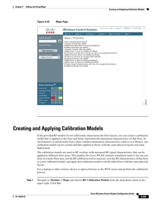
This document provides a configuration guide for Cisco Wireless Control System (WCS) software release 4.1. It includes chapters on installing and configuring WCS, adding maps and monitoring wireless devices, managing user accounts, configuring controllers and mobility groups, using templates, and other tasks. The guide is intended for network administrators to effectively manage Cisco's unified wireless network solution using WCS.


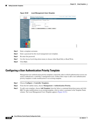
![Chapter 5 Adding and Using Maps
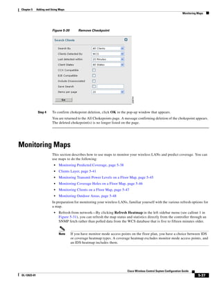
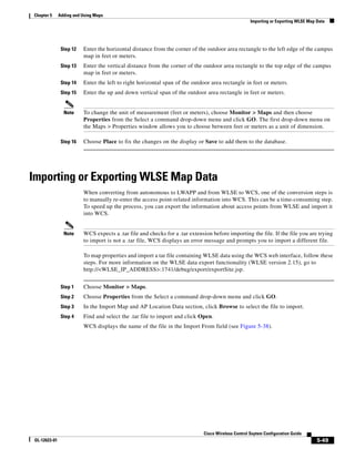
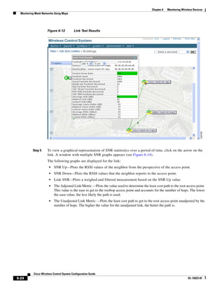
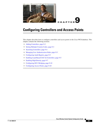
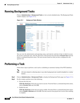
Creating Maps
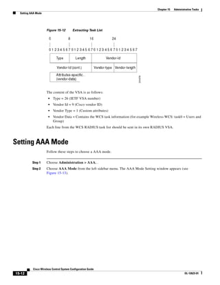
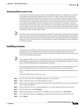
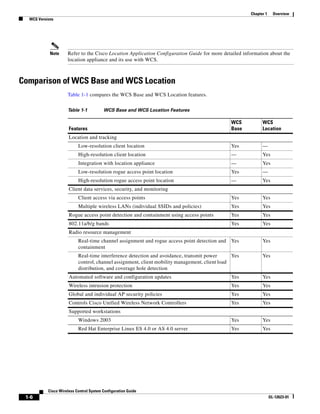
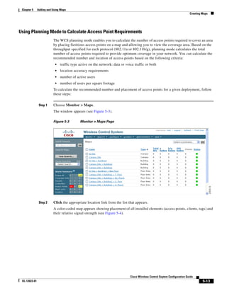
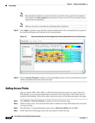
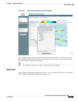
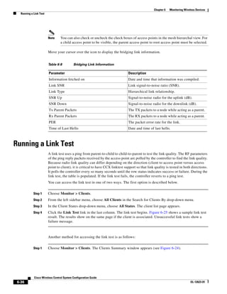
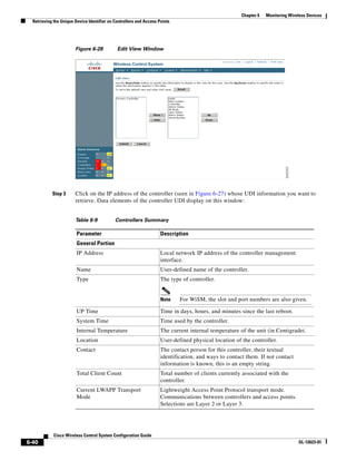
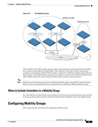
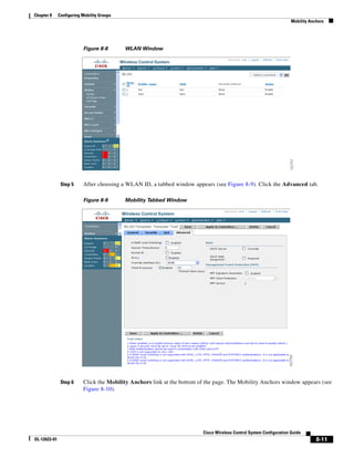
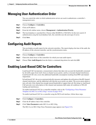
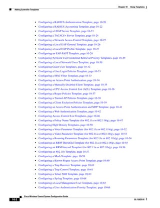
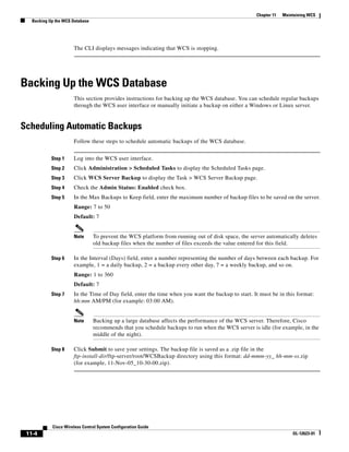
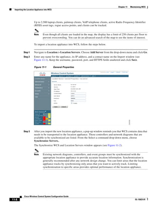
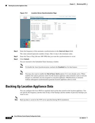
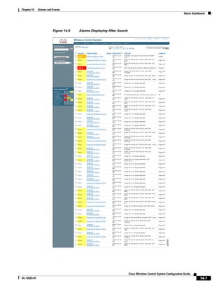
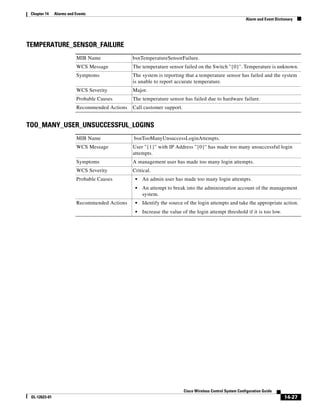
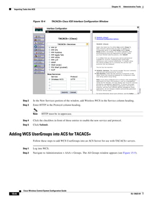
Table 5-2 Definition of Service Options
Service Options Description
Data/Coverage Select if data traffic is transmitted on the wireless LAN. The following densities are
used depending on the band and data rates:
Band Path Loss Model Date Rate (Mbps) Area (Sq. ft.)
(dBm)
802.11a –3.3 10-12 6000
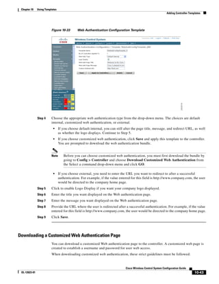
802.11a –3.3 15-18 4500
802.11a –3.5 10-12 5000
802.11a –3.5 15-18 3250
802.11bg –3.3 5 6500
802.11bg –3.3 6 4500
802.11bg –3.5 5 5500
802.11bg –3.5 6 3500
If you enable Advanced Options (click check box), you can select the desired safety
margin (aggressive, safe, or very safe) of the signal strength threshold for data.
• Aggressive = Minimum (–3 dBm)
• Safe = Medium (0 dBm)
• Very Safe = Maximum (+3 dBm)
Voice Select if voice traffic is transmitted on the wireless LAN.
If you enable Advanced Options (click check box), you can select the desired safety
margin (aggressive, safe, very safe or 7920-enabled) of the signal strength threshold
for voice.
• Aggressive = Minimum [–78 dBm (802.11a/b/g)]
• Safe = Medium [–75 dBm (802.11a/b/g)]
• Very Safe = Maximum [(–72 dBm (802.11a/b/g)]
• 7920_enabled = [(–72 dBm (802.11a); –67 dBm (802.11b/g)]
Location Select to ensure that the recommended access point calculation provides the true
location of an element within 10 meters at least 90% of the time.
To meet the criteria, access points are collocated within 70 feet of each other in a
hexagonal pattern employing staggered and perimeter placement.
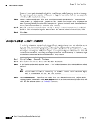
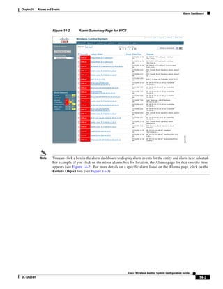
Note Each service option includes all services that are listed above it. For example,
if you check the Location box, the calculation considers data/coverage, voice,
and location in determining the optimum number of access points required.
Cisco Wireless Control System Configuration Guide
5-16 OL-12623-01](https://image.slidesharecdn.com/conbook-130317164116-phpapp01/85/Conbook-90-320.jpg)
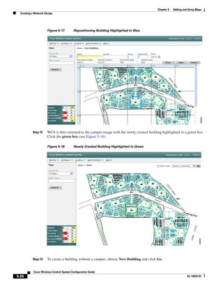
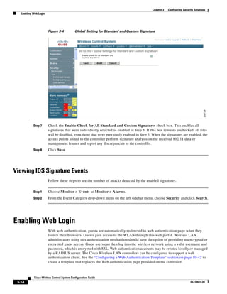
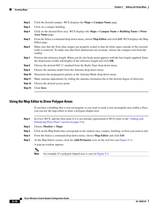
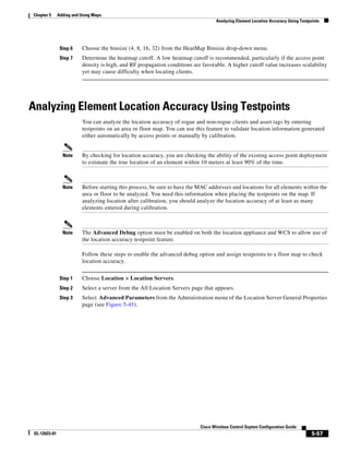
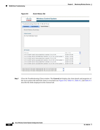
![Chapter 5 Adding and Using Maps
Creating a Network Design
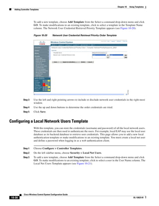
Step 14 Enter the building’s name, contact information, number of floors and basements, and dimension
information. Click Save. WCS is returned to the Monitor > Maps window.
Step 15 Click the hyperlink associated with the newly created building.
Step 16 On the Monitor > Maps > [Campus Name] > [Building Name] window, go to the drop-down menu and
choose New Floor Area. Click Go.
Step 17 Enter a name for the floor, a contact, a floor number, floor type, and height at which the access points
are installed and the path of the floor image. Click Next.
Note The Floor Type (RF Model) field specifies the type of environment on that specific floor. This
RF Model indicates the amount of RF signal attenuation likely to be present on that floor. If the
available models do not properly characterize a floor's makeup, details on how to create RF
models specific to a floor's attenuation characteristics are available in the “Creating and
Applying Calibration Models” section on page 5-53.
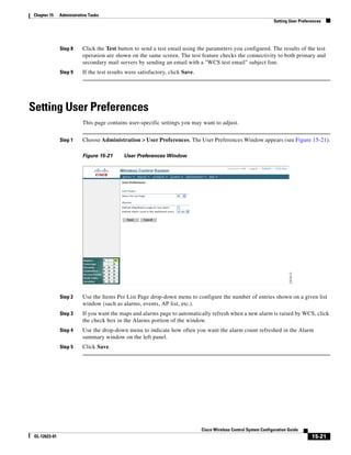
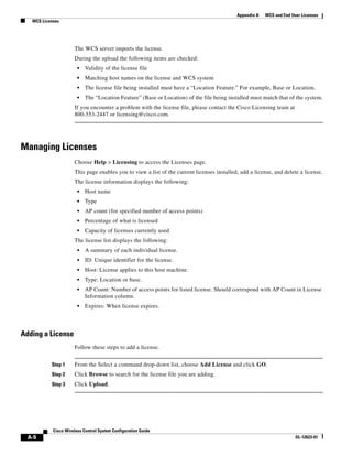
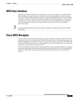
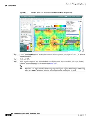
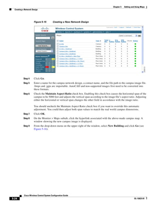
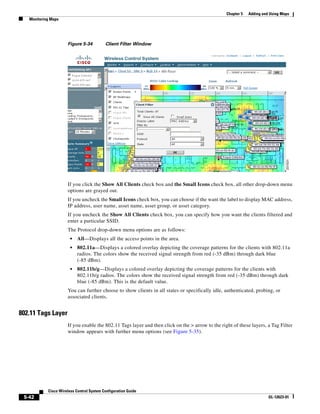
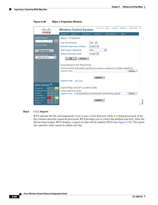
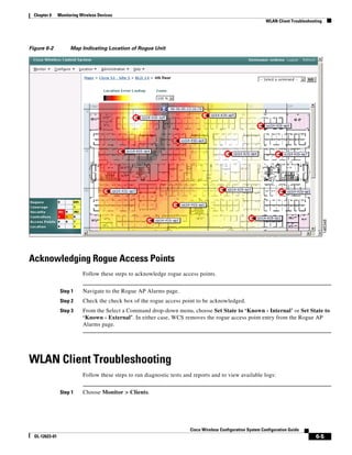
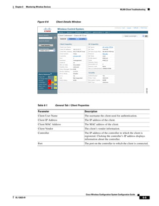
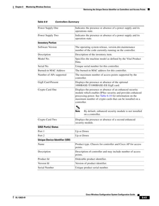
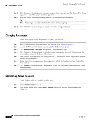
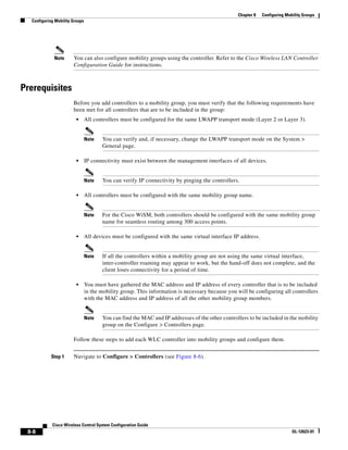
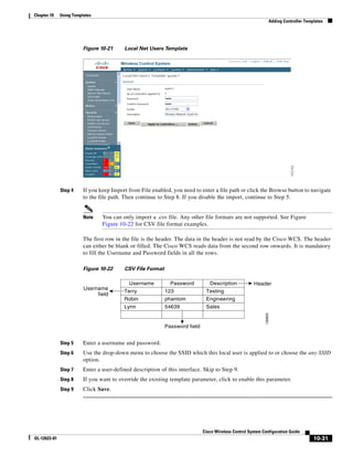
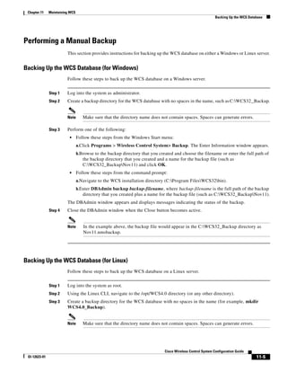
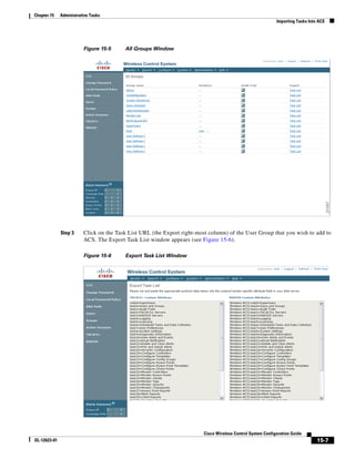
Step 18 If the floor area is a different dimension than the building, adjust floor dimensions by either making
numerical changes to the text fields under the Dimensions heading or by holding the Ctrl key and
clicking and dragging the blue box around the floor image. If the floor's location is offset from the upper
left corner of the building, change the placement of the floor within the building by either clicking and
dragging the blue box to the desired location or by altering the numerical values under the Coordinates
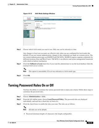
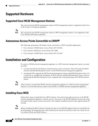
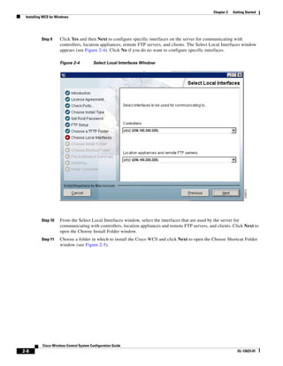
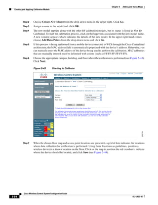
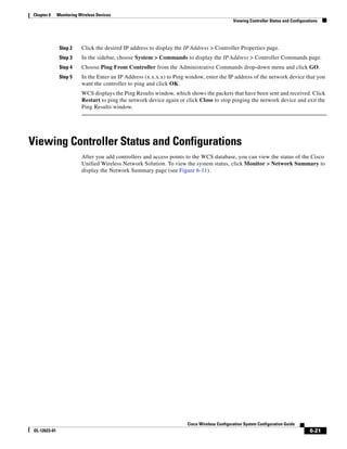
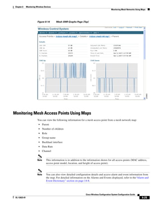
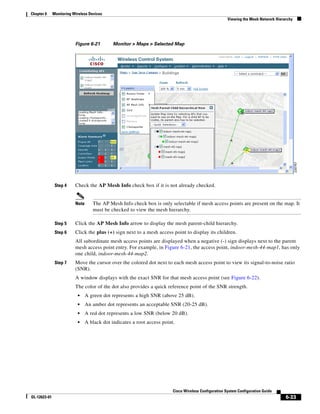
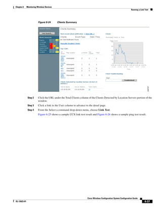
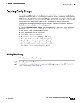
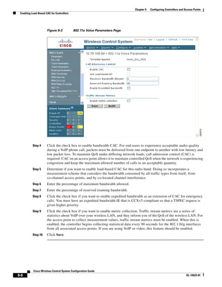
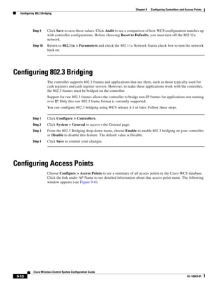
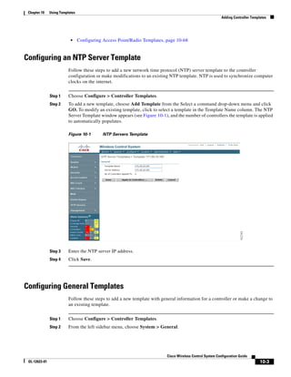
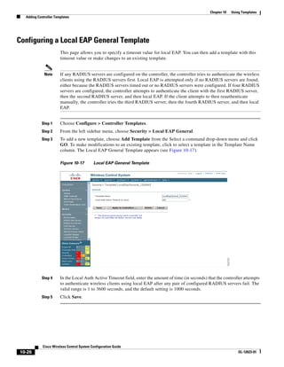
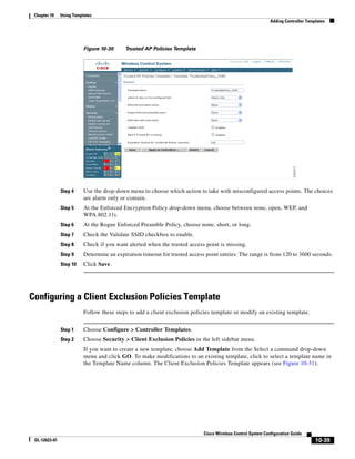
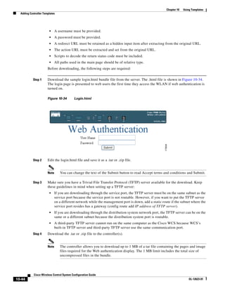
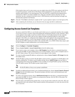
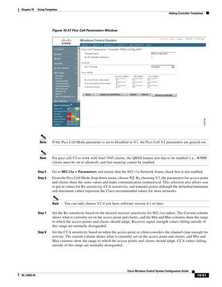
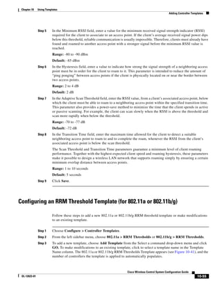
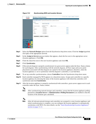
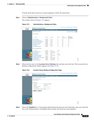
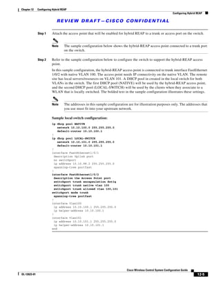
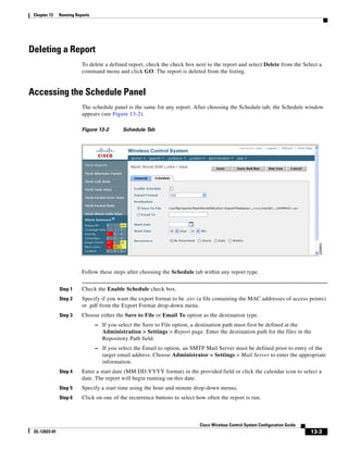
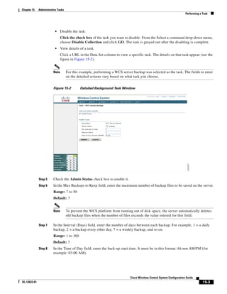
of top left corner heading (see Figure 5-19). After making changes to any numerical values, click Place.
Cisco Wireless Control Ssytem Configuration Guide
OL-12623-01 5-27](https://image.slidesharecdn.com/conbook-130317164116-phpapp01/85/Conbook-101-320.jpg)
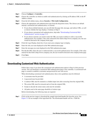
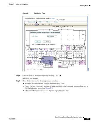
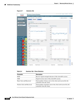
![Chapter 5 Adding and Using Maps
Creating a Network Design
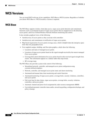
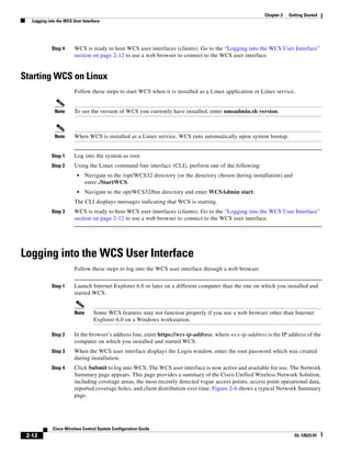
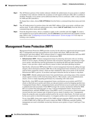
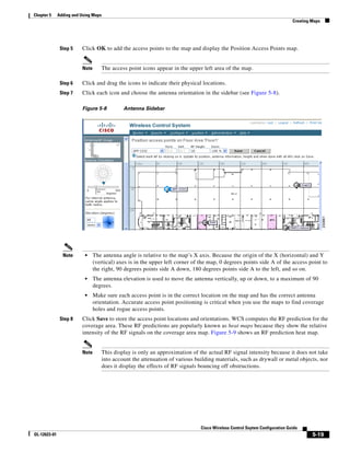
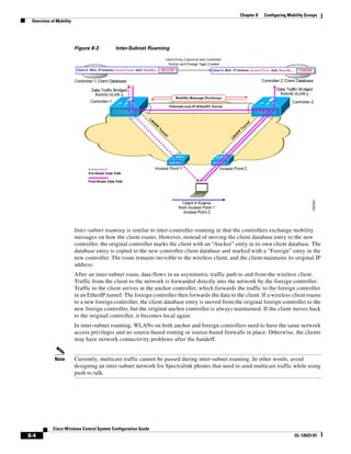
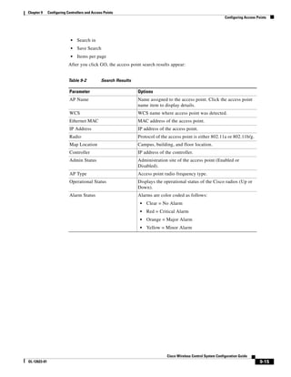
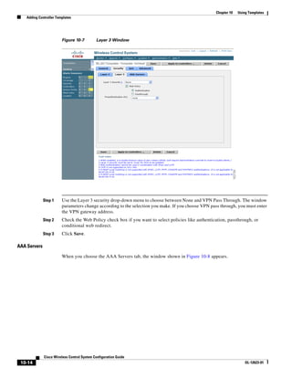
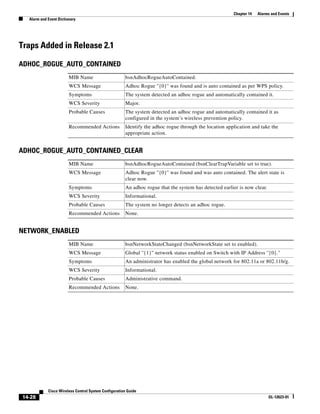
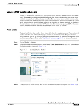
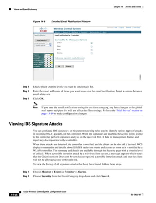
Figure 5-19 Repositioning Using Numerical Value Fields
Step 19 Adjust the floor’s characteristics with the WCS map editor by choosing the check box next to Launch
Map Editor. For an explanation of the map editor feature, see the “Using the Map Editor to Enhance
Floor Plans” section on page 5-9.
Step 20 At the new floor’s image window (Monitor > Maps > [CampusName] > [BuildingName] >
[FloorName]), go to the drop-down menu on the upper right and choose Add Access Points. Click Go.
Step 21 All access points that are connected to controllers are displayed. Even controllers that WCS is
configured to manage but which have not yet been added to another floor map are displayed. Select the
access points to be placed on the specific floor map by checking the boxes to the left of the access point
entries. Check the box to the left of the Name column to select all access points. Click OK.
Step 22 Each access point you have chosen to add to the floor map is represented by a gray circle (differentiated
by access point name or MAC address) and is lined up in the upper left part of the floor map. Drag each
access point to the appropriate location. (Access points turn blue when you click on them to relocate
Cisco Wireless Control System Configuration Guide
5-28 OL-12623-01](https://image.slidesharecdn.com/conbook-130317164116-phpapp01/85/Conbook-102-320.jpg)
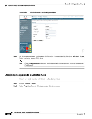
![Chapter 5 Adding and Using Maps
Creating a Network Design
them.) The small black arrow at the side of each access point represents Side A of each access point, and
each access point’s arrow must correspond with the direction in which the access points were installed.
(Side A is clearly noted on each 1000 series access point and has no relevance to the 802.11a radio.)
Step 23 To adjust the directional arrow, choose the appropriate orientation in the Antenna Angle drop-down
menu. Click Save when you are finished placing and adjusting each access point’s direction.
Note Access point placement and direction must directly reflect the actual access point deployment
or the system cannot pinpoint the device location.
Step 24 Repeat the above processes to create campuses, buildings, and floors until each device location is
properly detailed in a network design.
Changing Access Point Positions by Importing and Exporting a File
You can change an access point position by importing or exporting a file. The file contains only the lines
describing which access point you want to move. This option is a timesaver over manually changing
multiple access point positions. Follow these steps to change access point positions using the importing
or exporting of a file.
Step 1 Choose Monitor > Maps.
Step 2 From the Select a command drop-down menu, choose Properties.
Step 3 At the Unit of Dimenion drop-down menu, choose feet or meters.
Step 4 The Advanced Debug option must be enabled on both the location appliance and WCS so the location
accuracy testpoint is correct.
Step 5 In the Import/Export AP Placement portion of the window, click Browse to find the file you want to
import. The file in the [BuildingName], [FloorName], [APName], (aAngle), (bAngle), [X], [Y],
([aAngleElevation, bAngleElevation, Z]))) format must have already been created and added to WCS.
Note The parameters in square brackets are mandatory, and those in parentheses are optional.
Note Angles must be entered in radians (X,Y) , and the height is entered in feet. The aAngle and
bAngle range is from -2Pi (-6.28...) to 2Pi (6.28...), and the elevation ranges from -Pi (-3.14..)
to Pi (3.14..).
Step 6 Click Import. The RF calculation takes approximately two seconds per access point.
Cisco Wireless Control Ssytem Configuration Guide
OL-12623-01 5-29](https://image.slidesharecdn.com/conbook-130317164116-phpapp01/85/Conbook-103-320.jpg)
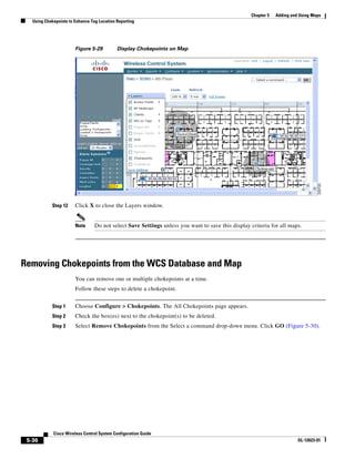
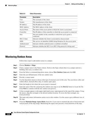
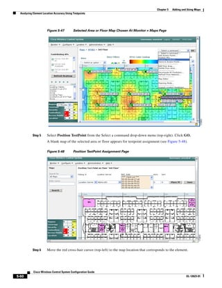

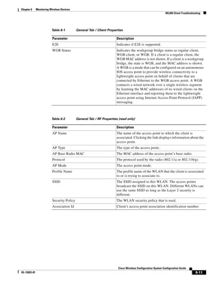
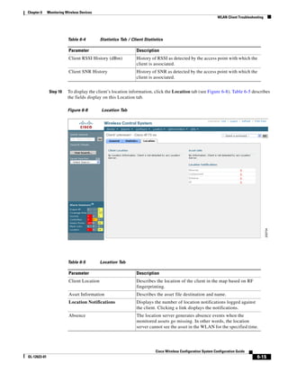
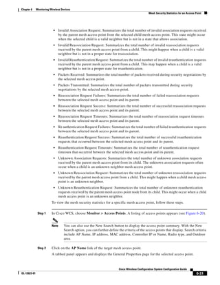
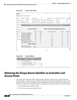

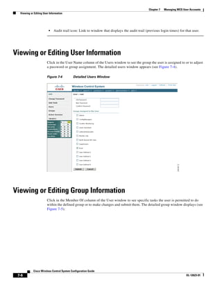
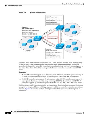


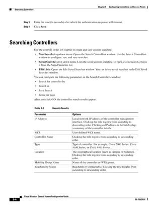

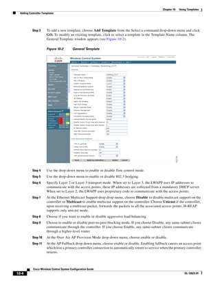
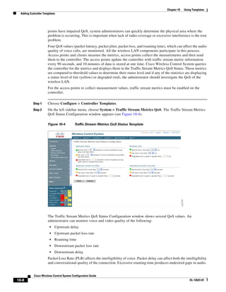
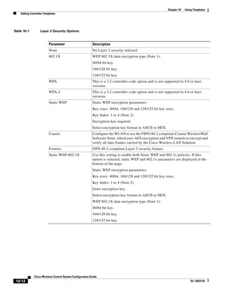
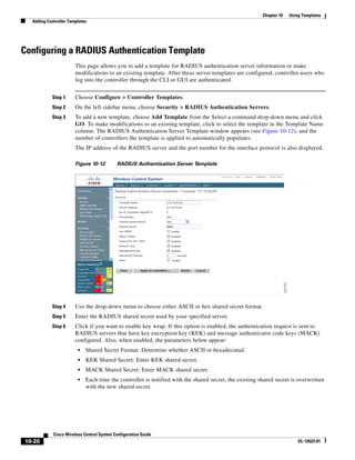
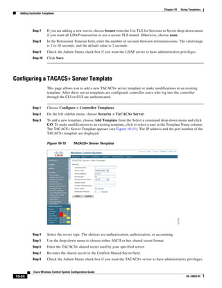
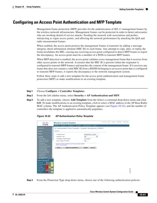
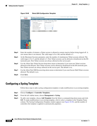
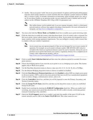


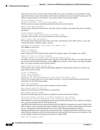
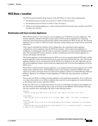
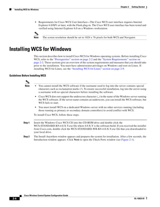
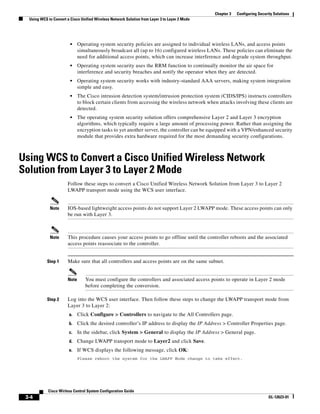
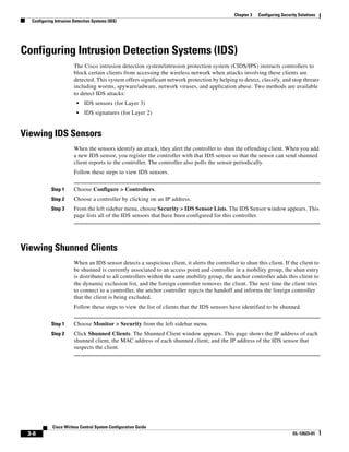
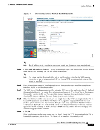
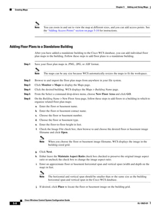
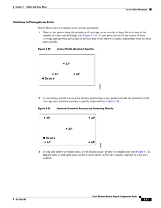
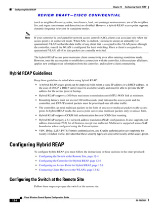
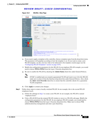
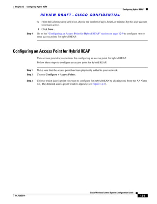
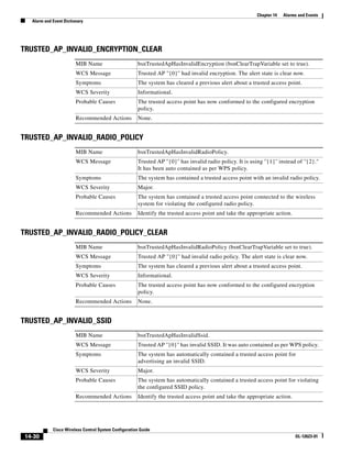
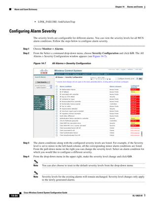
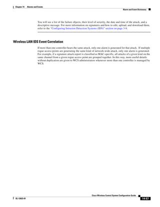
![Chapter 12 Configuring Hybrid REAP
Overview of Hybrid REAP
REVIEW DRAFT—CISCO CONFIDENTIAL
Overview of Hybrid REAP
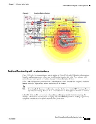
Hybrid REAP is a solution for branch office and remote office deployments. It enables customers to
configure and control access points in a branch or remote office from the corporate office through a wide
area network (WAN) link without deploying a controller in each office. There is no deployment
restriction on the number of hybrid-REAP access points per location. The hybrid-REAP access points
can switch client data traffic locally and perform client authentication locally when their connection to
the controller is lost. When they are connected to the controller, they can also send traffic back to the
controller.
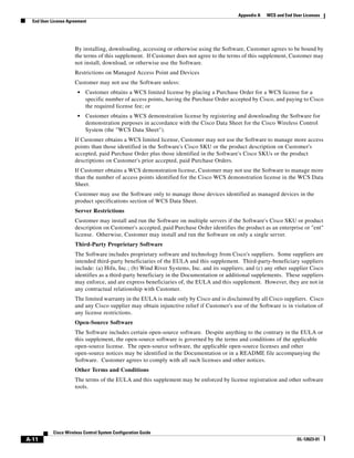
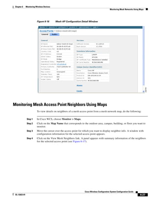
Hybrid REAP is supported only on the 1130AG and 1240AG access points and on the 2000 and 4400
series controllers, the Catalyst 3750G Integrated Wireless LAN Controller Switch, the Cisco WiSM, and
the Controller Network Module for Integrated Services Routers, and the controller within the Catalyst
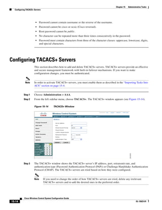
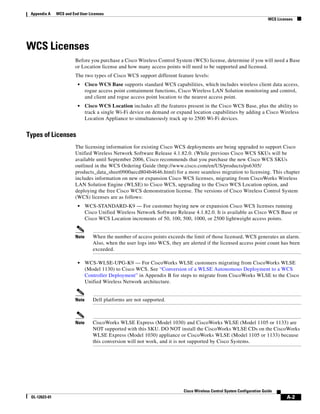
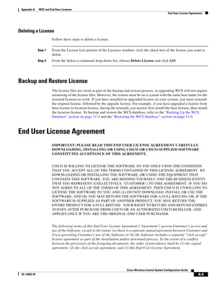
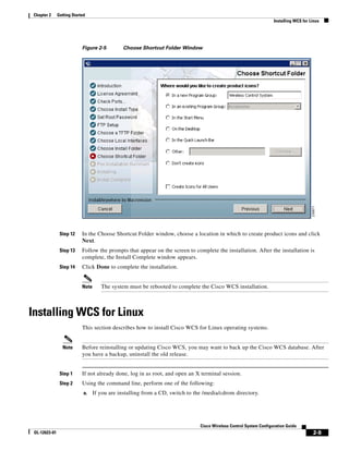
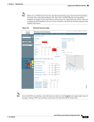
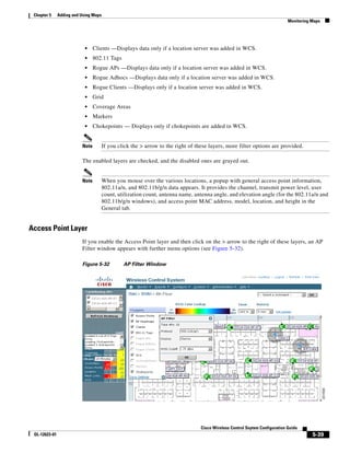
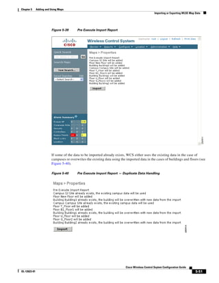
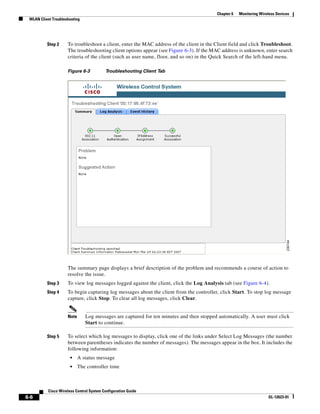
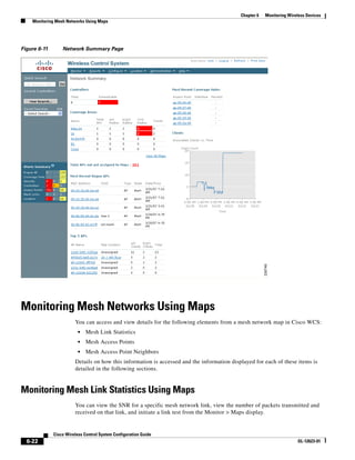
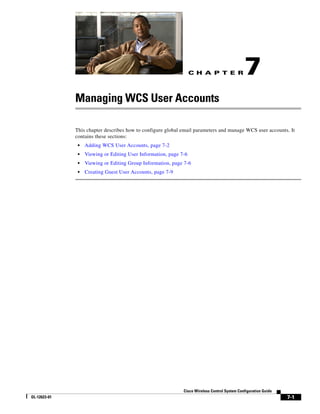
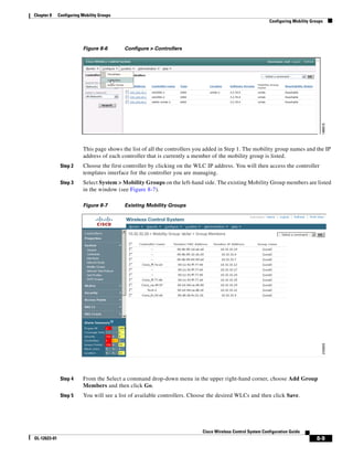
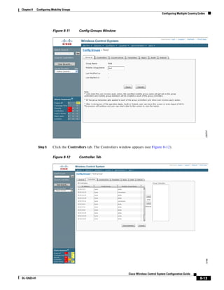
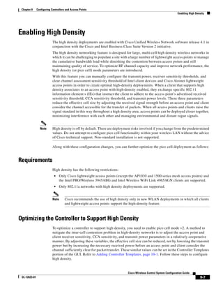
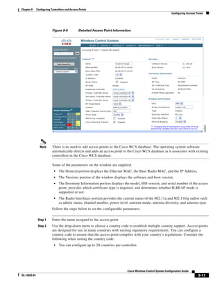
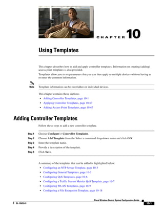
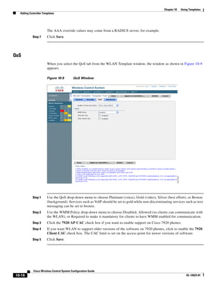
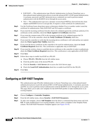
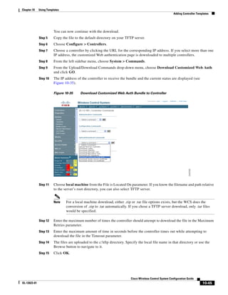
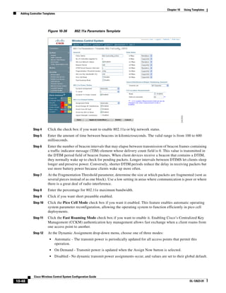
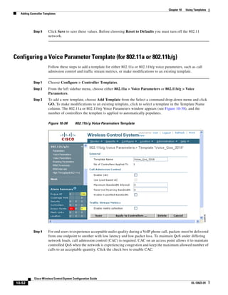
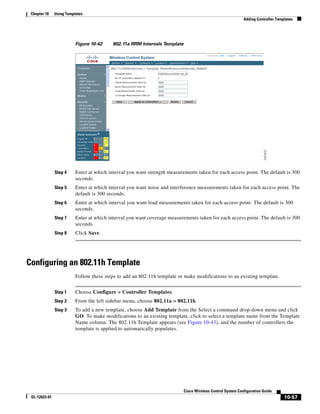
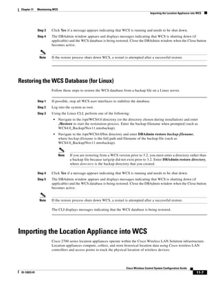
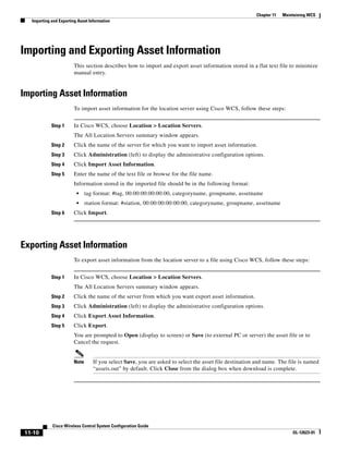
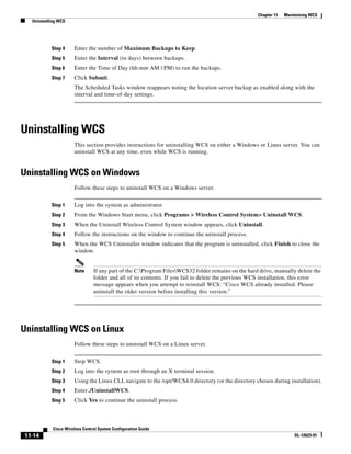
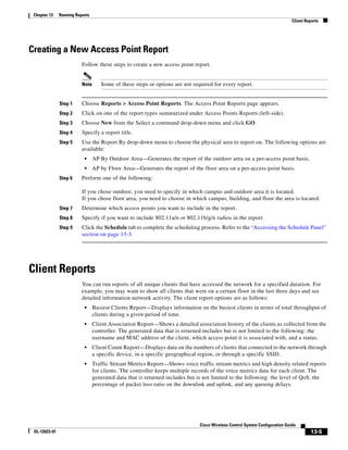
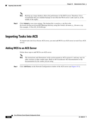
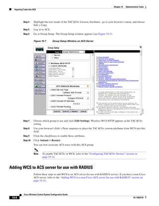
3750G Integrated Wireless LAN Controller Switch. Figure 12-1 illustrates a typical hybrid-REAP
deployment.
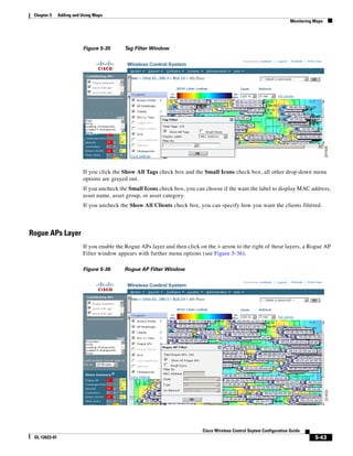
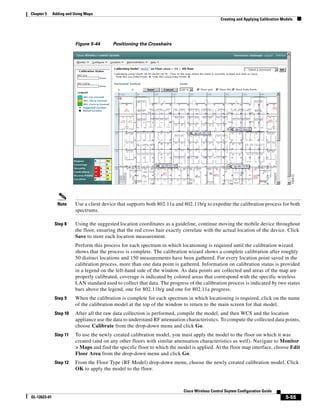
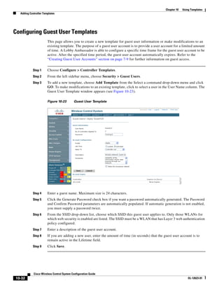
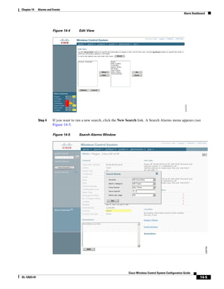
Figure 12-1 Hybrid REAP Deployment
Headquarters
WCS
DHCP server
WAN link VLAN 101
Controller
Local VLAN
802.1x Local switch
Management 10.10.99.2 AAA
AP-Manager 10.10.99.3 server
WLAN 99 Branch Trunk port
native VLAN 100
155859
Hybrid-REAP Access Points
Hybrid-REAP Authentication Process
When a hybrid-REAP access point boots up, it looks for a controller. If it finds one, it joins the controller,
downloads the latest software image from the controller and configuration information, and initializes
the radio. It saves the downloaded configuration in non-volatile memory for use in standalone mode.
A hybrid-REAP access point can learn the controller IP address in one of these ways:
• If the access point has been assigned an IP address fro m a DHCP server, it can discover a controller
through the regular LWAPP discovery process [Layer 3 broadcast, over-the-air provisioning
(OTAP), DNS, or DHCP option 43.]
Note OTAP does not work on the first boot out of the box.
Cisco Wireless Control System Configuration Guide
12-2 OL-12623-01](https://image.slidesharecdn.com/conbook-130317164116-phpapp01/85/Conbook-326-320.jpg)


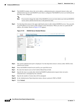
![Chapter 15 Administrative Tasks
Importing Tasks Into ACS
Step 4 Highlight the text inside of the RADIUS Custom Attributes, go to your browser’s menu, and choose
Edit > Copy.
Step 5 Log in to ACS.
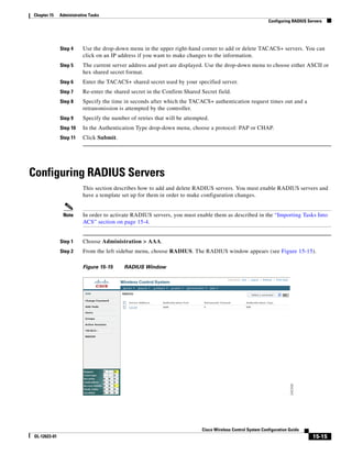
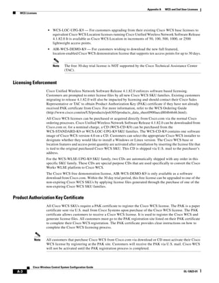
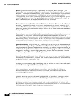
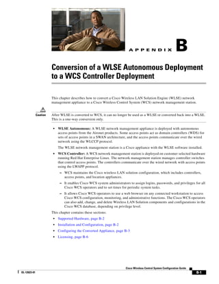
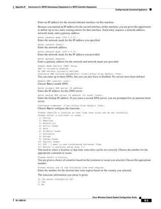
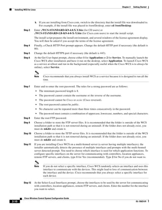
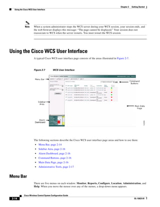
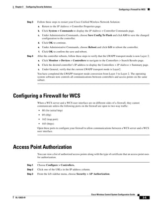
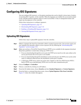
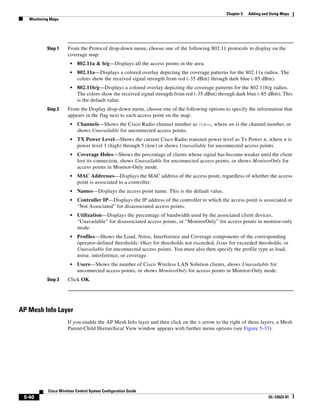
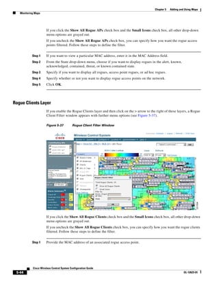
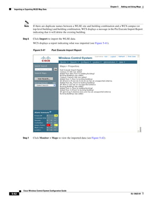
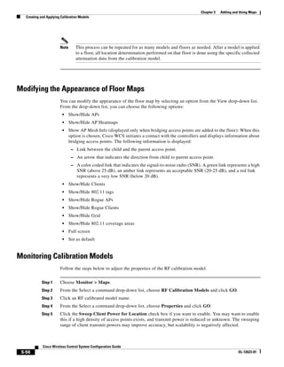
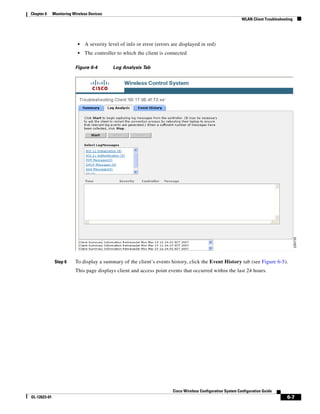
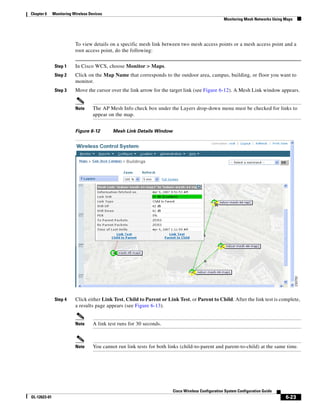
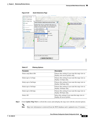
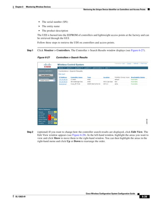
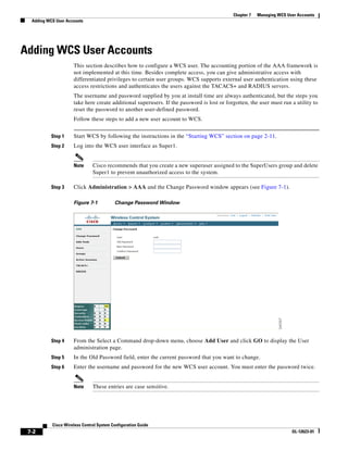
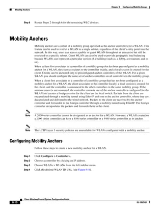
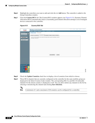
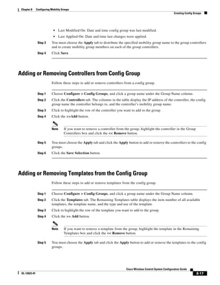
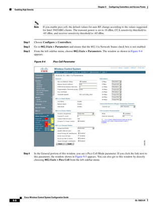
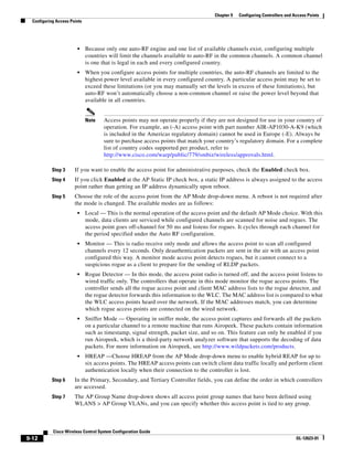
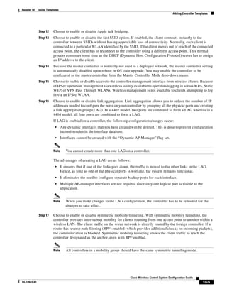
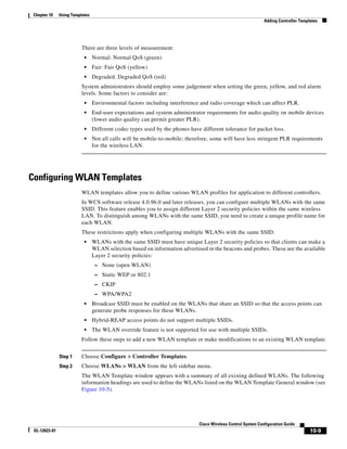
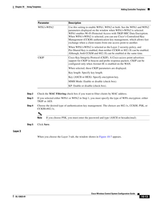
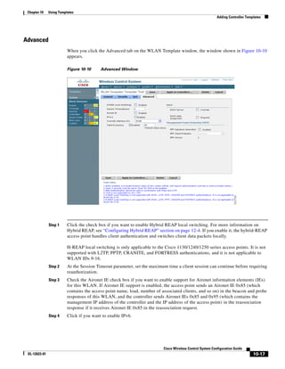
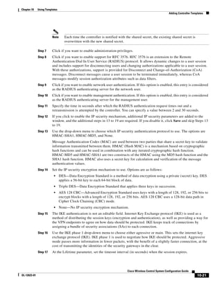
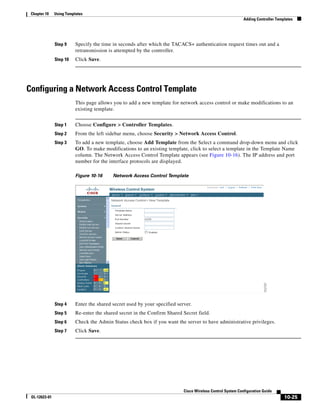
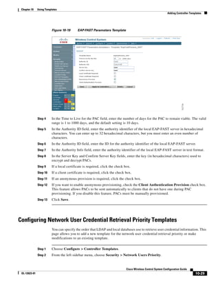
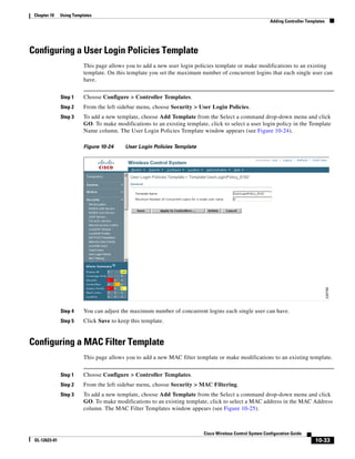
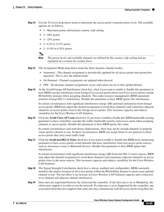
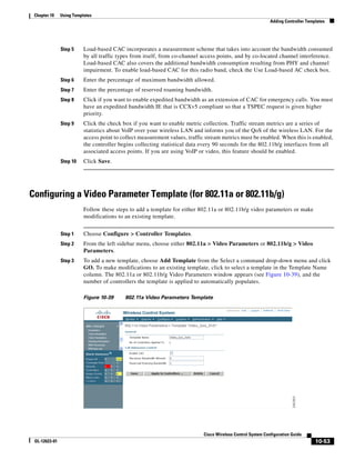
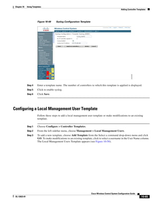
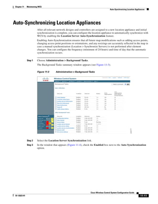
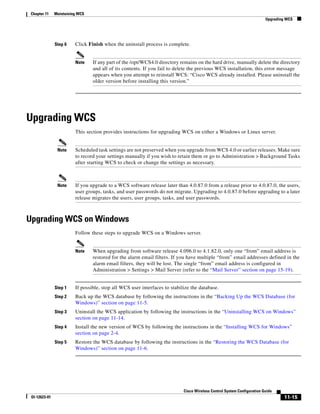
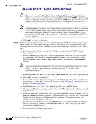
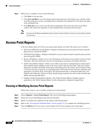
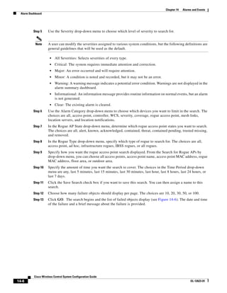
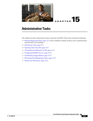
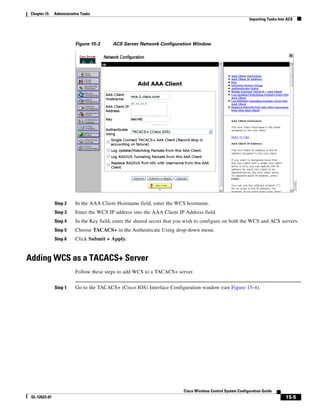
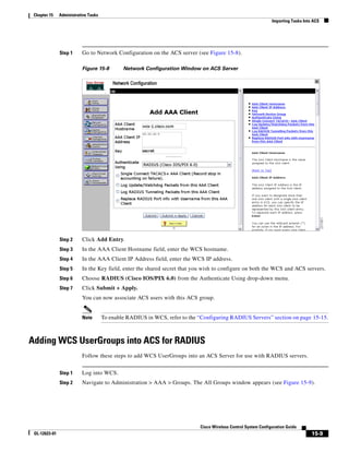
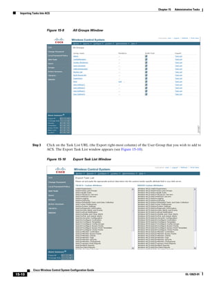
Step 6 Go to Group Setup. The Group Setup window appears (see Figure 15-11).
Figure 15-11 Group Setup Window on ACS Server
Step 7 Choose which group to use and click Edit Settings. Find [009001]cisco-av-pair under Cisco IOS/PIX
6.x RADIUS Attributes.
Step 8 Use your browser’s Edit > Paste sequence to place the RADIUS custom attributes from WCS into this
field.
Step 9 Click the checkboxes to enable these attributes.
Step 10 Click Submit + Restart.
You can now associate ACS users with this ACS group.
Note To enable RADIUS in WCS, refer to the “Configuring RADIUS Servers” section on page 15-15.
Adding WCS to a non-Cisco ACS server for use with RADIUS
WCS requires authorization information sent by a RADIUS server using the Vendor-Specific Attributes
(IETF RADIUS attribute number 26). The VSA contains the WCS RADIUS task list information (refer
to Figure 15-12).
Cisco Wireless Control System Configuration Guide
OL-12623-01 15-11](https://image.slidesharecdn.com/conbook-130317164116-phpapp01/85/Conbook-417-320.jpg)