This document provides a summary of the Cisco Wireless LAN Controller Configuration Guide:
- It describes Cisco's unified wireless network solution including single-controller and multiple-controller deployments. It also covers the operating system, security features, and supported controller platforms.
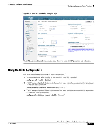
- It explains how to use the web browser and command-line interfaces to configure and manage controllers. This includes enabling interfaces, logging in, navigating menus, and using online help.
- It provides instructions for configuring the various controller ports and interfaces like management, AP-manager, virtual, and service-port interfaces using both the GUI and CLI. It also covers configuring dynamic interfaces.


![Preface
Conventions
Appendix A, “Safety Considerations and Translated Safety Warnings,” lists safety considerations and
translations of the safety warnings that apply to the Cisco Unified Wireless Network Solution products.
Appendix B, “Declarations of Conformity and Regulatory Information,” provides declarations of
conformity and regulatory information for the products in the Cisco Unified Wireless Network Solution.
Appendix C, “End User License and Warranty,” describes the end user license and warranty that apply
to the Cisco Unified Wireless Network Solution products.
Appendix D, “System Messages and LED Patterns,” lists system messages that can appear on the Cisco
Unified Wireless Network Solution interfaces and describes the LED patterns on controllers and
lightweight access points.
Appendix E, “Logical Connectivity Diagrams,”provides logical connectivity diagrams and related
software commands for controllers that are integrated into other Cisco products.
Conventions
This publication uses these conventions to convey instructions and information:
Command descriptions use these conventions:
• Commands and keywords are in boldface text.
• Arguments for which you supply values are in italic.
• Square brackets ([ ]) mean optional elements.
• Braces ({ }) group required choices, and vertical bars ( | ) separate the alternative elements.
• Braces and vertical bars within square brackets ([{ | }]) mean a required choice within an optional
element.
Interactive examples use these conventions:
• Terminal sessions and system displays are in screen font.
• Information you enter is in boldface screen font.
• Nonprinting characters, such as passwords or tabs, are in angle brackets (< >).
Notes, cautions, and timesavers use these conventions and symbols:
Note Means reader take note. Notes contain helpful suggestions or references to materials not contained in
this manual.
Caution Means reader be careful. In this situation, you might do something that could result equipment damage
or loss of data.
Cisco Wireless LAN Controller Configuration Guide
OL-9141-03 19](https://image.slidesharecdn.com/contcg40-oct-111011181122-phpapp01/85/Cont-cg40-oct-19-320.jpg)
![Preface
Conventions
Warning This warning symbol means danger. You are in a situation that could cause bodily injury. Before you
work on any equipment, be aware of the hazards involved with electrical circuitry and be familiar
with standard practices for preventing accidents. (To see translations of the warnings that appear
in this publication, refer to the appendix “Translated Safety Warnings.”)
Waarschuwing Dit waarschuwingssymbool betekent gevaar. U verkeert in een situatie die lichamelijk letsel kan
veroorzaken. Voordat u aan enige apparatuur gaat werken, dient u zich bewust te zijn van de bij
elektrische schakelingen betrokken risico’s en dient u op de hoogte te zijn van standaard
maatregelen om ongelukken te voorkomen. (Voor vertalingen van de waarschuwingen die in deze
publicatie verschijnen, kunt u het aanhangsel “Translated Safety Warnings” (Vertalingen van
veiligheidsvoorschriften) raadplegen.)
Varoitus Tämä varoitusmerkki merkitsee vaaraa. Olet tilanteessa, joka voi johtaa ruumiinvammaan. Ennen
kuin työskentelet minkään laitteiston parissa, ota selvää sähkökytkentöihin liittyvistä vaaroista ja
tavanomaisista onnettomuuksien ehkäisykeinoista. (Tässä julkaisussa esiintyvien varoitusten
käännökset löydät liitteestä "Translated Safety Warnings" (käännetyt turvallisuutta koskevat
varoitukset).)
Attention Ce symbole d’avertissement indique un danger. Vous vous trouvez dans une situation pouvant
entraîner des blessures. Avant d’accéder à cet équipement, soyez conscient des dangers posés par
les circuits électriques et familiarisez-vous avec les procédures courantes de prévention des
accidents. Pour obtenir les traductions des mises en garde figurant dans cette publication, veuillez
consulter l’annexe intitulée « Translated Safety Warnings » (Traduction des avis de sécurité).
Warnung Dieses Warnsymbol bedeutet Gefahr. Sie befinden sich in einer Situation, die zu einer
Körperverletzung führen könnte. Bevor Sie mit der Arbeit an irgendeinem Gerät beginnen, seien Sie
sich der mit elektrischen Stromkreisen verbundenen Gefahren und der Standardpraktiken zur
Vermeidung von Unfällen bewußt. (Übersetzungen der in dieser Veröffentlichung enthaltenen
Warnhinweise finden Sie im Anhang mit dem Titel “Translated Safety Warnings” (Übersetzung der
Warnhinweise).)
Avvertenza Questo simbolo di avvertenza indica un pericolo. Si è in una situazione che può causare infortuni.
Prima di lavorare su qualsiasi apparecchiatura, occorre conoscere i pericoli relativi ai circuiti
elettrici ed essere al corrente delle pratiche standard per la prevenzione di incidenti. La traduzione
delle avvertenze riportate in questa pubblicazione si trova nell’appendice, “Translated Safety
Warnings” (Traduzione delle avvertenze di sicurezza).
Advarsel Dette varselsymbolet betyr fare. Du befinner deg i en situasjon som kan føre til personskade. Før du
utfører arbeid på utstyr, må du være oppmerksom på de faremomentene som elektriske kretser
innebærer, samt gjøre deg kjent med vanlig praksis når det gjelder å unngå ulykker. (Hvis du vil se
oversettelser av de advarslene som finnes i denne publikasjonen, kan du se i vedlegget "Translated
Safety Warnings" [Oversatte sikkerhetsadvarsler].)
Aviso Este símbolo de aviso indica perigo. Encontra-se numa situação que lhe poderá causar danos
fisicos. Antes de começar a trabalhar com qualquer equipamento, familiarize-se com os perigos
relacionados com circuitos eléctricos, e com quaisquer práticas comuns que possam prevenir
possíveis acidentes. (Para ver as traduções dos avisos que constam desta publicação, consulte o
apêndice “Translated Safety Warnings” - “Traduções dos Avisos de Segurança”).
Cisco Wireless LAN Controller Configuration Guide
20 OL-9141-03](https://image.slidesharecdn.com/contcg40-oct-111011181122-phpapp01/85/Cont-cg40-oct-20-320.jpg)
![Preface
Related Publications
¡Advertencia! Este símbolo de aviso significa peligro. Existe riesgo para su integridad física. Antes de manipular
cualquier equipo, considerar los riesgos que entraña la corriente eléctrica y familiarizarse con los
procedimientos estándar de prevención de accidentes. (Para ver traducciones de las advertencias
que aparecen en esta publicación, consultar el apéndice titulado “Translated Safety Warnings.”)
Varning! Denna varningssymbol signalerar fara. Du befinner dig i en situation som kan leda till personskada.
Innan du utför arbete på någon utrustning måste du vara medveten om farorna med elkretsar och
känna till vanligt förfarande för att förebygga skador. (Se förklaringar av de varningar som
förekommer i denna publikation i appendix "Translated Safety Warnings" [Översatta
säkerhetsvarningar].)
Related Publications
These documents provide complete information about the Cisco Unified Wireless Network Solution:
• Quick Start Guide: Cisco 2000 Series Wireless LAN Controllers
• Quick Start Guide: Cisco 4400 Series Wireless LAN Controllers
• Cisco Wireless LAN Controller Command Reference
• Cisco Wireless Control System Configuration Guide
• Quick Start Guide: Cisco Wireless Control System for Microsoft Windows
• Quick Start Guide: Cisco Wireless Control System for Linux
• Quick start guide and hardware installation guide for your specific lightweight access point
Click this link to browse to the Cisco Support and Documentation page:
http://www.cisco.com/cisco/web/support/index.html
• Cisco 1800 Series Routers Hardware Installation Guide
• Cisco AP HWIC Wireless Configuration Guide
• Cisco Router and Security Device Manager (SDM) Quick Start Guide
• Cisco Aironet 2.4-GHz Articulated Dipole Antenna (AIR-ANT4941)
• Cisco Aironet High Gain Omnidirectional Ceiling Mount Antenna (AIR-ANT1728)
• Mounting Instructions for the Cisco Aironet 6.5 dBi Diversity Patch Wall Mount Antenna
• Cisco Aironet 2 dBi Diversity Omnidirectional Ceiling Mount Antenna (AIR-ANT5959)
• Cisco Multiband 2.4/5GHz Articulated Dipole Antenna (AIR-ANT1841)
• Cisco Multiband 2.4/5G Diversity Omnidirectional Ceiling Mount Antenna (AIR-ANT1828)
• Cisco Multiband 2.4/5G Patch Wall Mount Antenna (AIR-ANT1859)
• Mounting Instructions for the Cisco Diversity Omnidirectional Ceiling Mount Antenna
• Mounting Instructions for the Cisco Patch Wall Mount Antenna
Related documents from the Cisco TAC Web pages include:
• Antenna Cabling
Cisco Wireless LAN Controller Configuration Guide
OL-9141-03 21](https://image.slidesharecdn.com/contcg40-oct-111011181122-phpapp01/85/Cont-cg40-oct-21-320.jpg)


![Chapter 1 Overview
Controller Platforms
Controller Platforms
Controllers are enterprise-class high-performance wireless switching platforms that support 802.11a and
802.11b/802.11g protocols. They operate under control of the operating system, which includes the
Radio Resource Management (RRM), creating a Cisco UWN Solution that can automatically adjust to
real-time changes in the 802.11 RF environment. The controllers are built around high-performance
network and security hardware, resulting in highly-reliable 802.11 enterprise networks with unparalleled
security.
The following controllers are supported for use with software release 4.0:
• Cisco 2000 series controllers
• Cisco 2100 series controllers (4.0.206.0 and later)
• Cisco 4400 series controllers
• Catalyst 6500 Series Wireless Services Module (WiSM)
• Cisco 28/37/38xx Series Integrated Services Router with Controller Network Module
• Catalyst 3750G Integrated Wireless LAN Controller Switch
The first three controllers are stand-alone platforms. The remaining three controllers are integrated into
Cisco switch and router products.
Cisco 2000 and 2100 Series Controllers
The Cisco 2000 and 2100 series (2106) Wireless LAN Controllers work in conjunction with Cisco
lightweight access points and the Cisco Wireless Control System (WCS) to provide system-wide
wireless LAN functions.
Each 2000 and 2100 series controller controls up to six lightweight access points for multi-controller
architectures typical of enterprise branch deployments. It may also be used for single controller
deployments for small and medium-sized business environments.
Caution Do not connect a power-over-Ethernet (PoE) cable to the controller’s console port. Doing so may damage
the controller.
Note Wait at least 20 seconds before reconnecting an access point to the controller. Otherwise, the controller
may fail to detect the device.
Features Not Supported
These hardware features are not supported on 2000 and 2100 series controllers:
• Power over Ethernet (PoE) [2000 series controllers only]
Note Ports 7 and 8 on 2100 series controllers are PoE ports.
• Service port (separate out-of-band management 10/100-Mbps Ethernet interface)
Cisco Wireless LAN Controller Configuration Guide
OL-9141-03 1-9](https://image.slidesharecdn.com/contcg40-oct-111011181122-phpapp01/85/Cont-cg40-oct-31-320.jpg)


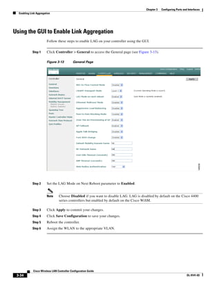
![Chapter 3 Configuring Ports and Interfaces
Configuring the Management, AP-Manager, Virtual, and Service-Port Interfaces
Note The management interface uses the controller’s factory-set distribution system MAC address.
Step 2 Enter config wlan disable wlan-number to disable each WLAN that uses the management interface for
distribution system communication.
Step 3 Enter these commands to define the management interface:
• config interface address management ip-addr ip-netmask gateway
• config interface vlan management {vlan-id | 0}
Note Enter 0 for an untagged VLAN or a non-zero value for a tagged VLAN. Cisco recommends
that only tagged VLANs be used on the controller.
• config interface port management physical-ds-port-number
• config interface dhcp management ip-address-of-primary-dhcp-server
[ip-address-of-secondary-dhcp-server]
• config interface acl management access-control-list-name
Note See Chapter 5 for more information on ACLs.
Step 4 Enter save config to save your changes.
Step 5 Enter show interface detailed management to verify that your changes have been saved.
Using the CLI to Configure the AP-Manager Interface
Follow these steps to display and configure the AP-manager interface parameters using the CLI.
Step 1 Enter show interface summary to view the current interfaces.
Note If the system is operating in Layer 2 mode, the AP-manager interface is not listed.
Step 2 Enter show interface detailed ap-manager to view the current AP-manager interface settings.
Step 3 Enter config wlan disable wlan-number to disable each WLAN that uses the AP-manager interface for
distribution system communication.
Cisco Wireless LAN Controller Configuration Guide
OL-9141-03 3-13](https://image.slidesharecdn.com/contcg40-oct-111011181122-phpapp01/85/Cont-cg40-oct-65-320.jpg)
![Chapter 3 Configuring Ports and Interfaces
Configuring the Management, AP-Manager, Virtual, and Service-Port Interfaces
Step 4 Enter these commands to define the AP-manager interface:
• config interface address ap-manager ip-addr ip-netmask gateway
• config interface vlan ap-manager {vlan-id | 0}
Note Enter 0 for an untagged VLAN or a non-zero value for a tagged VLAN. Cisco recommends
that only tagged VLANs be used on the controller.
• config interface port ap-manager physical-ds-port-number
• config interface dhcp ap-manager ip-address-of-primary-dhcp-server
[ip-address-of-secondary-dhcp-server]
• config interface acl ap-manager access-control-list-name
Note See Chapter 5 for more information on ACLs.
Step 5 Enter save config to save your changes.
Step 6 Enter show interface detailed ap-manager to verify that your changes have been saved.
Using the CLI to Configure the Virtual Interface
Follow these steps to display and configure the virtual interface parameters using the CLI.
Step 1 Enter show interface detailed virtual to view the current virtual interface settings.
Step 2 Enter config wlan disable wlan-number to disable each WLAN that uses the virtual interface for
distribution system communication.
Step 3 Enter these commands to define the virtual interface:
• config interface address virtual ip-address
Note For ip-address, enter any fictitious, unassigned, and unused gateway IP address, such as
1.1.1.1.
• config interface hostname virtual dns-host-name
Step 4 Enter reset system. At the confirmation prompt, enter Y to save your configuration changes to NVRAM.
The controller reboots.
Step 5 Enter show interface detailed virtual to verify that your changes have been saved.
Cisco Wireless LAN Controller Configuration Guide
3-14 OL-9141-03](https://image.slidesharecdn.com/contcg40-oct-111011181122-phpapp01/85/Cont-cg40-oct-66-320.jpg)
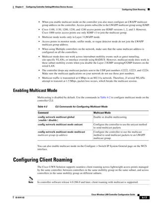
![Chapter 3 Configuring Ports and Interfaces
Configuring Dynamic Interfaces
Using the CLI to Configure the Service-Port Interface
Follow these steps to display and configure the service-port interface parameters using the CLI.
Step 1 Enter show interface detailed service-port to view the current service-port interface settings.
Note The service-port interface uses the controller’s factory-set service-port MAC address.
Step 2 Enter these commands to define the service-port interface:
• To configure the DHCP server: config interface dhcp service-port ip-address-of-primary-dhcp-
server [ip-address-of-secondary-dhcp-server]
• To disable the DHCP server: config interface dhcp service-port none
• To configure the IP address: config interface address service-port ip-addr ip-netmask gateway
Step 3 The service port is used for out-of-band management of the controller. If the management workstation
is in a remote subnet, you may need to add a route on the controller in order to manage the controller
from that remote workstation. To do so, enter this command:
config route network-ip-addr ip-netmask gateway
Step 4 Enter save config to save your changes.
Step 5 Enter show interface detailed service-port to verify that your changes have been saved.
Configuring Dynamic Interfaces
This section provides instructions for configuring dynamic interfaces using either the GUI or CLI.
Using the GUI to Configure Dynamic Interfaces
Follow these steps to create new or edit existing dynamic interfaces using the GUI.
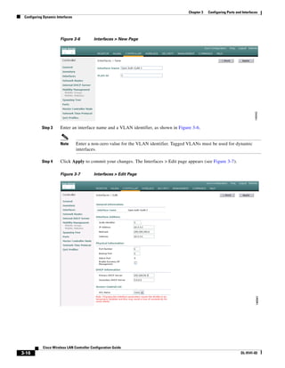
Step 1 Click Controller > Interfaces to access the Interfaces page (see Figure 3-5).
Step 2 Perform one of the following:
• To create a new dynamic interface, click New. The Interfaces > New page appears (see Figure 3-6).
Go to Step 3.
• To modify the settings of an existing dynamic interface, click the interface’s Edit link. The
Interfaces > Edit page for that interface appears (see Figure 3-7). Go to Step 5.
• To delete an existing dynamic interface, click the interface’s Remove link.
Cisco Wireless LAN Controller Configuration Guide
OL-9141-03 3-15](https://image.slidesharecdn.com/contcg40-oct-111011181122-phpapp01/85/Cont-cg40-oct-67-320.jpg)

![Chapter 3 Configuring Ports and Interfaces
Configuring Dynamic Interfaces
Step 4 Enter these commands to configure dynamic interfaces:
• config interface create operator-defined-interface-name {vlan-id | x}
Note Enter a non-zero value for the VLAN identifier. Tagged VLANs must be used for dynamic
interfaces.
• config interface address operator-defined-interface-name ip-addr ip-netmask [gateway]
• config interface vlan operator-defined-interface-name {vlan-id | 0}
• config interface port operator-defined-interface-name physical-ds-port-number
• config interface dhcp operator-defined-interface-name ip-address-of-primary-dhcp-server
[ip-address-of-secondary-dhcp-server]
• config interface operator-defined-interface-name quarantine enable
Note Use this command if you want to configure this VLAN as unhealthy. Doing so causes the
data traffic of any client that is assigned to this VLAN to pass through the controller, even
if the WLAN is configured for local switching. This command is generally used for clients
that are associated to a hybrid-REAP access point and the access point’s controller is
configured for network access control (NAC). See Chapter 12 for more information on
hybrid REAP.
• config interface acl operator-defined-interface-name access-control-list-name
Note See Chapter 5 for more information on ACLs.
Step 5 Enter save config to save your changes.
Step 6 Enter show interface detailed operator-defined-interface-name and show interface summary to verify
that your changes have been saved.
Note If desired, you can enter config interface delete operator-defined-interface-name to delete a dynamic
interface.
Cisco Wireless LAN Controller Configuration Guide
3-18 OL-9141-03](https://image.slidesharecdn.com/contcg40-oct-111011181122-phpapp01/85/Cont-cg40-oct-70-320.jpg)


![Chapter 3 Configuring Ports and Interfaces
Configuring a 4400 Series Controller to Support More Than 48 Access Points
Step 5 Enter the appropriate interface parameters.
Note Do not define a backup port for an AP-Manager Interface. Port redundancy is not supported for
AP-manager interfaces. If the AP-manager interface fails, all of the access points connected to
the controller through that interface are evenly distributed among the other configured
AP-manager interfaces.
Step 6 To make the interface an AP-manager interface, check the Enable Dynamic AP Management check
box.
Step 7 Click Save Configuration to save your settings.
Step 8 Repeat this procedure for each additional AP-manager interface that you want to create.
Connecting Additional Ports
To support more than 48 access points with a 4400 series controller in Layer 2 mode, you must connect
more controller ports to individual broadcast domains that are completely separated. Table 3-8 provides
an example in which each controller port is connected to an individual switch.
Table 3-8 Example Port Configuration on a 4404 Controller in Layer 2 Mode
[Distribution Switch 1]=Trunk=[Distribution Switch 2]
dot1q access access access
VLAN 250 VLAN 992 VLAN 993 VLAN 994
port 1 port 2 port 3 port 4
VLANs 992, 993, and 994 (used here as VLAN examples) are access VLANs, and you can assign them
any VLAN IDs that you choose. An IP address is not allocated to these VLANs, and these ports are
access ports only. To connect additional access points, assign the access port connecting the access point
to VLAN 992, 993, or 994. The access point then joins the controller using that isolated VLAN with
Layer 2 LWAPP. All Layer 2 LWAPP traffic received on ports 2, 3, and 4 egresses the management port
(configured as port 1) on VLAN 250 with a dot1q tag of 250.
With a Layer 2 LWAPP configuration, you should distribute access points across VLANs 250, 992, 993,
and 994 manually. Ideally, you should distribute 25 access points per port to balance a total of 100 access
points. If you have less than 100 access points, divide the number of access points by 4 and distribute
that number. For example, 48 total access points divided by 4 equals 12 access points per 4404 port. You
could connect 48 access points to port 1, 48 to port 2, and only 2 to port 3, but this unbalanced
distribution does not provide the best throughput performance for wireless clients and is not
recommended.
It does not matter where you connect ports 2, 3, and 4 as long as they can communicate with the access
points configured for their isolated VLANs. If VLAN 250 is a widely used infrastructure VLAN within
your network and you notice network congestion, redistribute all of the access points connected to
VLAN 250 to ports 2, 3, and 4. Port 1 still remains connected to VLAN 250 as the management network
interface but transports data only from wireless clients proxied by the controller.
Cisco Wireless LAN Controller Configuration Guide
OL-9141-03 3-41](https://image.slidesharecdn.com/contcg40-oct-111011181122-phpapp01/85/Cont-cg40-oct-93-320.jpg)


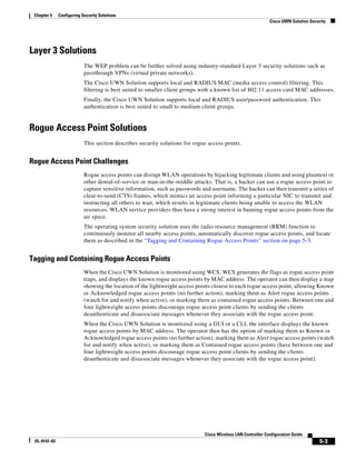
![Chapter 4 Configuring Controller SettingsWireless Device Access
Configuring Voice and Video Parameters
4. To see the TSM statistics for a particular client and the access point to which this client is associated,
enter this command:
show client tsm {802.11a | 802.11b} client_mac [ap_mac | all]
The optional all command shows all access points to which this client has associated. Information
similar to the following appears:
AP Interface Mac: 00:0b:85:01:02:03
Client Interface Mac: 00:01:02:03:04:05
Measurement Duration: 90 seconds
Timestamp 1st Jan 2006, 06:35:80
UpLink Stats
================
Average Delay (5sec intervals)............................35
Delay less than 10 ms.....................................20
Delay bet 10 - 20 ms......................................20
Delay bet 20 - 40 ms......................................20
Delay greater than 40 ms..................................20
Total packet Count.........................................80
Total packet lost count (5sec).............................10
Maximum Lost Packet count(5sec)............................5
Average Lost Packet count(5secs)...........................2
DownLink Stats
================
Average Delay (5sec intervals)............................35
Delay less than 10 ms.....................................20
Delay bet 10 - 20 ms......................................20
Delay bet 20 - 40 ms......................................20
Delay greater than 40 ms..................................20
Total packet Count.........................................80
Total packet lost count (5sec).............................10
Maximum Lost Packet count(5sec)............................5
Average Lost Packet count(5secs)...........................2
Note The statistics are shown in 90-second intervals. The timestamp field shows the specific
interval when the statistics were collected.
5. To see the TSM statistics for a particular access point and a particular client associated to this access
point, enter this command:
show ap stats {802.11a | 802.11b} ap_name tsm [client_mac | all]
The optional all command shows all clients associated to this access point. Information similar to
the following appears:
AP Interface Mac: 00:0b:85:01:02:03
Client Interface Mac: 00:01:02:03:04:05
Measurement Duration: 90 seconds
Timestamp 1st Jan 2006, 06:35:80
UpLink Stats
================
Average Delay (5sec intervals)............................35
Delay less than 10 ms.....................................20
Delay bet 10 - 20 ms......................................20
Delay bet 20 - 40 ms......................................20
Delay greater than 40 ms..................................20
Total packet Count.........................................80
Total packet lost count (5sec).............................10
Cisco Wireless LAN Controller Configuration Guide
Ol-9141-03 4-33](https://image.slidesharecdn.com/contcg40-oct-111011181122-phpapp01/85/Cont-cg40-oct-127-320.jpg)


![Chapter 6 Configuring WLANsWireless Device Access
Configuring WLANs
• To disable or enable the 802.1X authentication, use this command:
config wlan security 802.1X {enable | disable} wlan-id
After you enable 802.1X authentication, the controller sends EAP authentication packets between
the wireless client and the authentication server. This command allows all EAP-type packets to be
sent to and from the controller.
• If you want to change the 802.1X encryption level for a WLAN, use this command:
config wlan security 802.1X encryption wlan-id [40 | 104 | 128]
– Use the 40 option to specify 40/64-bit encryption.
– Use the 104 option to specify 104/128-bit encryption. (This is the default encryption setting.)
– Use the 128 option to specify 128/152-bit encryption.
• If you want to configure Cisco Aironet 802.11a/b/g Wireless LAN Client Adapters (CB21AG and
PI21AG) running PEAP-GTC to authenticate to a controller through a one-time password to a token
server, use these commands:
– config advanced eap identity-request-timeout—Configures the EAP identity request timeout
value in seconds. The default setting is 1 second.
– config advanced eap identity-request-retries—Configures the EAP identity request
maximum retries value. The default setting is 20.
– config advanced eap request-timeout—Configures the EAP request timeout value in seconds.
The default setting is 1 second.
– config advanced eap request-retries—Configures the EAP request maximum retries value.
The default setting is 2.
– show advanced eap—Shows the values that are currently configured for the config advanced
eap commands. Information similar to the following appears:
EAP-Identity-Request Timeout (seconds)........... 1
EAP-Identity-Request Max Retries................. 20
EAP-Request Timeout (seconds).................... 1
EAP-Request Max Retries.......................... 2
Configuring a WLAN for Both Static and Dynamic WEP
You can configure up to four WLANs to support static WEP keys, and you can also configure dynamic
WEP on any of these static-WEP WLANs. Follow these guidelines when configuring a WLAN for both
static and dynamic WEP:
• The static WEP key and the dynamic WEP key must be the same length.
• When you configure both static and dynamic WEP as the Layer-2 security policy, no other security
policies can be specified. That is, you cannot configure web authentication. However, when you
configure either the dynamic WEP or the static WEP as the Layer 2 security policy, you can
configure web authentication.
WPA1 and WPA2
Wi-Fi Protected Access (WPA or WPA1) and WPA2 are standards-based security solutions from the
Wi-Fi Alliance that provide data protection and access control for wireless LAN systems. WPA1 is
compatible with the IEEE 802.11i standard but was implemented prior to the standard's ratification;
WPA2 is the Wi-Fi Alliance's implementation of the ratified IEEE 802.11i standard.
Cisco Wireless LAN Controller Configuration Guide
6-8 OL-1926-06OL-9141-03](https://image.slidesharecdn.com/contcg40-oct-111011181122-phpapp01/85/Cont-cg40-oct-180-320.jpg)


![Chapter 6 Configuring WLANsWireless Device Access
Configuring WLANs
CKIP
Cisco Key Integrity Protocol (CKIP) is a Cisco-proprietary security protocol for encrypting 802.11
media. CKIP improves 802.11 security in infrastructure mode using key permutation, message integrity
check (MIC), and message sequence number. Software release 4.0 supports CKIP with static key. For
this feature to operate correctly, you must enable Aironet information elements (IEs) for the WLAN.
A lightweight access point advertises support for CKIP in beacon and probe response packets by adding
an Aironet IE and setting one or both of the CKIP negotiation bits [key permutation and multi-modular
hash message integrity check (MMH MIC)]. Key permutation is a data encryption technique that uses
the basic encryption key and the current initialization vector (IV) to create a new key. MMH MIC
prevents bit-flip attacks on encrypted packets by using a hash function to compute message integrity
code.
The CKIP settings specified in a WLAN are mandatory for any client attempting to associate. If the
WLAN is configured for both CKIP key permutation and MMH MIC, the client must support both. If
the WLAN is configured for only one of these features, the client must support only this CKIP feature.
CKIP requires that 5-byte and 13-byte encryption keys be expanded to 16-byte keys. The algorithm to
perform key expansion happens at the access point. The key is appended to itself repeatedly until the
length reaches 16 bytes. All lightweight access points except the AP1000 support CKIP.
You can configure CKIP through either the GUI or the CLI.
Using the GUI to Configure CKIP
Follow these steps to configure a WLAN for CKIP using the controller GUI.
Step 1 To enable Aironet IEs for this WLAN, check the Aironet IE check box under Cisco Client Extension
(CCX).
Step 2 Click WLANs to access the WLANs page.
Cisco Wireless LAN Controller Configuration Guide
6-12 OL-1926-06OL-9141-03](https://image.slidesharecdn.com/contcg40-oct-111011181122-phpapp01/85/Cont-cg40-oct-184-320.jpg)


![Chapter 6 Configuring WLANsWireless Device Access
Configuring WLANs
Note When the controller is in Layer 2 mode and WMM is enabled, you must put the access points on
a trunk port in order to allow them to join the controller.
Enabling 7920 Support Mode
The 7920 support mode contains two options:
• Support for 7920 phones that require call admission control (CAC) to be configured on and
advertised by the client device (these are typically older 7920 phones)
• Support for 7920 phones that require CAC to be configured on and advertised by the access point
(these are typically newer 7920 phones)
Note When access point-controlled CAC is enabled, the access point sends out a Cisco proprietary
CAC Information Element (IE) and does not send out the standard QBSS IE.
Enter this command to enable 7920 support mode for phones that require client-controlled CAC:
config wlan 7920-support client-cac-limit {enabled | disabled} wlan-id
Note You cannot enable both WMM mode and client-controlled CAC mode on the same WLAN.
Enter this command to enable 7920 support mode for phones that require access point-controlled CAC:
config wlan 7920-support ap-cac-limit {enabled | disabled} wlan-id
QBSS Information Elements Sometimes Degrade 7920 Phone Performance
If your WLAN contains both 1000 series access points and Cisco 7920 wireless phones, do not enable
the WMM or AP-CAC-LIMIT QBSS information elements. Do not enter either of these commands:
config wlan 7920-support ap-cac-limit enable wlan-id
config wlan wmm [allow | require] wlan-id
The information sent by 1000 series access points in the WMM and AP-CAC-LIMIT QBSS information
elements is inaccurate and could result in degradation of voice quality 7920 wireless phones. This issue
does not affect the CLIENT-CAC-LIMIT QBSS IE, which you enable using this command:
config wlan 7920-support client-cac-limit enable wlan-id
The CLIENT-CAC-LIMIT QBSS IE is the only QBSS IE that should be used in networks containing
both 1000 series access points and 7920 wireless phones.
Configuring Quality of Service Profiles
You can use the GUI or CLI to configure the Platinum, Gold, Silver, and Bronze QoS profiles.
Using the GUI to Configure QoS Profiles
To configure the Platinum, Gold, Silver, and Bronze QoS profiles using the GUI, follow these steps.
Step 1 Disable the 802.11a and 802.11b/g networks so that you can configure the QoS profiles.
Cisco Wireless LAN Controller Configuration Guide
OL-1926-06OL-9141-03 6-19](https://image.slidesharecdn.com/contcg40-oct-111011181122-phpapp01/85/Cont-cg40-oct-191-320.jpg)


![Chapter 6 Configuring WLANsWireless Device Access
Configuring WLANs
Figure 6-16 ACS Server Configuration
Step 4 Check the [009001] cisco-av-pair check box.
Step 5 Enter the following Cisco AV-pairs in the [009001] cisco-av-pair edit box to specify the URL to which
the user is redirected and the conditions under which the redirect takes place, respectively:
url-redirect=http://url
url-redirect-acl=acl_name
Cisco Wireless LAN Controller Configuration Guide
OL-1926-06OL-9141-03 6-33](https://image.slidesharecdn.com/contcg40-oct-111011181122-phpapp01/85/Cont-cg40-oct-205-320.jpg)


![Chapter 7 Controlling Lightweight Access Points
Cisco Aironet 1510 Series Lightweight Outdoor Mesh Access Points
Step 2 Click New. The MAC Filters > New page appears (see Figure 7-5).
Figure 7-5 MAC Filters > New Page
Step 3 In the MAC Address field, enter the MAC address of the access point.
Step 4 From the WLAN ID drop-down box, choose “Any WLAN.”
Step 5 In the Description field, enter a description of the access point. The text that you enter identifies the
access point on the controller. You may want to include an abbreviated name and the last few digits of
the MAC address, such as ap1510:62:39:10.
Step 6 From the Interface Name drop-down box, choose the controller interface to which the access point is to
connect.
Step 7 Click Apply to commit your changes. The access point now appears in the list of MAC filters on the
MAC Filtering page.
Step 8 Click Save Configuration to save your changes.
Step 9 Repeat this procedure to add the MAC addresses of additional access points to the list.
Using the CLI to Add the MAC Address of the Access Point to the Controller Filter List
Follow these steps to add a MAC filter entry for the access point on the controller using the controller
CLI.
Step 1 To add the MAC address of the access point to the controller filter list, enter this command:
config macfilter add ap_mac wlan_id interface [description]
A value of zero (0) for the wlan_id parameter specifies any WLAN, and a value of zero (0) for the
interface parameter specifies none. You can enter up to 32 characters for the optional description
parameter.
Step 2 To save your changes, enter this command:
save config
Cisco Wireless LAN Controller Configuration Guide
OL-9141-03 7-13](https://image.slidesharecdn.com/contcg40-oct-111011181122-phpapp01/85/Cont-cg40-oct-221-320.jpg)


![Chapter 7 Controlling Lightweight Access Points
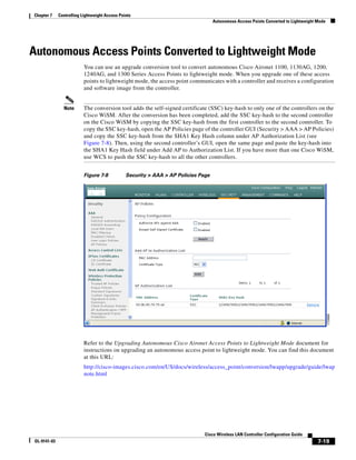
Autonomous Access Points Converted to Lightweight Mode
Using DHCP Option 43
Cisco 1000 series access points use a string format for DHCP option 43, whereas Cisco Aironet access
points use the type-length-value (TLV) format for DHCP option 43. DHCP servers must be programmed
to return the option based on the access point’s DHCP Vendor Class Identifier (VCI) string (DHCP
Option 60). Table 7-1 lists the VCI strings for Cisco access points capable of operating in lightweight
mode.
Table 7-1 VCI Strings For Lightweight Access Points
Access Point VCI String
Cisco 1000 Series Airespace 1200
Cisco Aironet 1130 Series Cisco AP c1130
Cisco Aironet 1200 Series Cisco AP c1200
Cisco Aironet 1240 Series Cisco AP c1240
This is the format of the TLV block:
• Type: 0xf1 (decimal 241)
• Length: Number of controller IP addresses * 4
• Value: List of the IP addresses of controller management interfaces
Refer to the product documentation for your DHCP server for instructions on configuring DHCP option
43. The Upgrading Autonomous Cisco Aironet Access Points to Lightweight Mode document contains
example steps for configuring option 43 on a DHCP server.
Using a Controller to Send Debug Commands to Access Points Converted to
Lightweight Mode
Enter this command to enable the controller to send debug commands to an access point converted to
lightweight mode:
config ap remote-debug [enable | disable | exc-command] Cisco_AP
When this feature is enabled, the controller sends debug commands to the converted access point as
character strings. You can send any debug command supported by Cisco Aironet access points that run
Cisco IOS software in lightweight mode.
Converted Access Points Send Crash Information to Controller
When a converted access point unexpectedly reboots, the access point stores a crash file on its local flash
memory at the time of crash. After the unit reboots, it sends the reason for the reboot to the controller.
If the unit rebooted because of a crash, the controller pulls up the crash file using existing LWAPP
messages and stores it in the controller flash memory. The crash info copy is removed from the access
point flash memory when the controller pulls it from the access point.
Cisco Wireless LAN Controller Configuration Guide
7-22 OL-9141-03](https://image.slidesharecdn.com/contcg40-oct-111011181122-phpapp01/85/Cont-cg40-oct-230-320.jpg)


![Chapter 7 Controlling Lightweight Access Points
Performing a Link Test
With the CCX link test, the controller can also test the link quality in the access point-to-client direction.
The controller issues link-test requests to the client, and the client records the RF parameters [received
signal strength indicator (RSSI), signal-to-noise ratio (SNR), etc.] of the received request packet in the
response packet. Both the link-test requestor and responder roles are implemented on the access point
and controller. Therefore, not only can the access point or controller initiate a link test to a CCX v4
client, but a CCX v4 client can initiate a link test to the access point or controller.
The controller shows these link-quality metrics for CCX link tests in both directions (out: access point
to client; in: client to access point):
• Signal strength in the form of RSSI (minimum, maximum, and average)
• Signal quality in the form of SNR (minimum, maximum, and average)
• Total number of packets that are retried
• Maximum retry count for a single packet
• Number of lost packets
• Data rate of a successfully transmitted packet
The controller shows this metric regardless of direction:
• Link test request/reply round-trip time (minimum, maximum, and average)
The 4.0 release of controller software supports CCX versions 1 through 4. CCX support is enabled
automatically for every WLAN on the controller and cannot be disabled. The controller stores the CCX
version of the client in its client database and uses it to limit the features for this client. If a client does
not support CCX v4, the controller performs a ping link test on the client. If a client supports CCX v4,
the controller performs a CCX link test on the client. If a client times out during a CCX link test, the
controller switches to the ping link test automatically. See the “Configuring Quality of Service Profiles”
section on page 6-19 for more information on CCX.
Note CCX is not supported on the AP1030.
Follow the instructions in this section to perform a link test using either the GUI or the CLI.
Cisco Wireless LAN Controller Configuration Guide
7-28 OL-9141-03](https://image.slidesharecdn.com/contcg40-oct-111011181122-phpapp01/85/Cont-cg40-oct-236-320.jpg)


![Chapter 7 Controlling Lightweight Access Points
Configuring Power over Ethernet
Use these commands to obtain information about CDP neighbors on the controller.
1. To see the status of CDP and to view CDP protocol information, enter this command:
show cdp
2. To see a list of all CDP neighbors on all interfaces, enter this command:
show cdp neighbors [detail]
The optional detail command provides detailed information for the controller’s CDP neighbors.
Note This command shows only the CDP neighbors of the controller. It does not show the CDP
neighbors of the controller’s associated access points.
3. To see all CDP entries in the database, enter this command:
show cdp entry all
4. To see various traffic-related parameters on a given port (for example, packets sent and received,
CRC errors, and so on), enter this command:
show cdp traffic
5. To see the CDP status for a specific access point, enter this command:
show ap cdp Cisco_AP
6. To see the CDP status for all access points that are connected to this controller, enter this command:
show ap cdp all
Use these commands to obtain CDP debug information for the controller.
1. To obtain debug information related to CDP packets, enter this command:
debug cdp packets
2. To obtain debug information related to CDP events, enter this command:
debug cdp events
Configuring Power over Ethernet
When an LWAPP-enabled access point (such as an AP1131 or AP1242) is powered by a power injector
that is connected to a Cisco pre-Intelligent Power Management (pre-IPM) switch, you need to configure
power over Ethernet (PoE), also known as inline power. You can configure PoE through either the GUI
or the CLI.
Using the GUI to Configure Power over Ethernet
Follow these steps to configure PoE using the controller GUI.
Step 1 Click Wireless and then the Detail link of the desired access point. The All APs > Details page appears
(see Figure 7-13).
Cisco Wireless LAN Controller Configuration Guide
OL-9141-03 7-33](https://image.slidesharecdn.com/contcg40-oct-111011181122-phpapp01/85/Cont-cg40-oct-241-320.jpg)


![Chapter 10 Configuring Radio Resource ManagementWireless Device Access
Configuring CCX Radio Management Features
Using the CLI to Obtain CCX Radio Management Information
Use these commands to obtain information about CCX radio management on the controller.
1. To see the CCX broadcast location measurement request configuration for all access points
connected to this controller in the 802.11a or 802.11b/g network, enter this command:
show advanced {802.11a | 802.11b} ccx global
2. To see the CCX broadcast location measurement request configuration for a particular access point
in the 802.11a or 802.11b/g network, enter this command:
show advanced {802.11a | 802.11b} ccx ap Cisco_AP
3. To see the clients configured for location calibration, enter this command:
show client location-calibration summary
4. To see the RSSI reported for both antennas on each access point that heard the client, enter this
command:
show client detail client_mac
Use these commands to obtain radio management debug information for the controller.
1. To debug CCX broadcast measurement request activity, enter this command:
debug airewave-director message {enable | disable}
2. To debug client location calibration activity, enter this command:
debug ccxrm [all | error | warning | message | packet | detail {enable | disable}]
3. To debug the output for forwarded probes and their included RSSI for both antennas, enter this
command:
debug dot11 load-balancing
Cisco Wireless LAN Controller Configuration Guide
10-32 OL-1926-06OL-9141-03](https://image.slidesharecdn.com/contcg40-oct-111011181122-phpapp01/85/Cont-cg40-oct-300-320.jpg)


![Chapter 11 Configuring Mobility GroupsWireless Device Access
Configuring Auto-Anchor Mobility
Step 5 Click Save Configuration to save your changes.
Step 6 Repeat Step 3 and Step 5 to set any other controllers as mobility anchors for this WLAN.
Step 7 Configure the same set of anchor controllers on every controller in the mobility group.
Using the CLI to Configure Auto-Anchor Mobility
Use these commands to configure auto-anchor mobility using the CLI.
1. Enter config wlan disable wlan-id to disable the WLAN for which you are configuring anchor
controllers.
2. To create a new mobility anchor for the WLAN, enter one of these commands:
– config mobility group anchor add wlan-id anchor-controller-ip-address
– config wlan mobility anchor add wlan-id anchor-controller-ip-address
Note The wlan-id must exist and be disabled, and the anchor-controller-ip-address must be a
member of the default mobility group.
Note Auto-anchor mobility is enabled for the WLAN when you configure the first anchor
controller.
3. To delete a mobility anchor for the WLAN, enter one of these commands:
– config mobility group anchor delete wlan-id anchor-controller-ip-address
– config wlan mobility anchor delete wlan-id anchor-controller-ip-address
Note The wlan-id must exist and be disabled.
Note Deleting the last anchor disables the auto-anchor mobility feature and resumes normal
mobility for new associations.
4. To see the list of controllers configured as mobility anchors for a specific WLAN, enter one of these
commands:
– show mobility anchor [wlan-id]
– show wlan mobility anchor [wlan-id]
Note The wlan-id is optional and constrains the list to the anchors in a particular WLAN. To see
all of the mobility anchors on your system, enter show mobility anchor.
5. To save your settings, enter this command:
save config
Cisco Wireless LAN Controller Configuration Guide
11-14 OL-9141-03](https://image.slidesharecdn.com/contcg40-oct-111011181122-phpapp01/85/Cont-cg40-oct-314-320.jpg)


![Chapter 12 Configuring Hybrid REAPWireless Device Access
Overview of Hybrid REAP
Overview of Hybrid REAP
Hybrid REAP is a solution for branch office and remote office deployments. It enables customers to
configure and control two or three access points in a branch or remote office from the corporate office
through a wide area network (WAN) link without deploying a controller in each office.
Note In release 4.0.206.0 and greater, Hybrid REAP can be used with up to eight access points.
The hybrid-REAP access points can switch client data traffic locally and perform client authentication
locally when their connection to the controller is lost. When they are connected to the controller, they
can also send traffic back to the controller.
Hybrid REAP is supported only on the 1130AG and 1240AG access points and on the 2000 and 4400
series controllers, the Catalyst 3750G Integrated Wireless LAN Controller Switch, the Cisco WiSM, and
the Controller Network Module for Integrated Services Routers. Figure 12-1 illustrates a typical
hybrid-REAP deployment.
Figure 12-1 Hybrid REAP Deployment
Headquarters
WCS
DHCP server
WAN link VLAN 101
Controller
Local VLAN
802.1x Local switch
Management 10.10.99.2 AAA
AP-Manager 10.10.99.3 server
WLAN 99 Branch Trunk port
native VLAN 100
155859
Hybrid-REAP Access Points
Hybrid-REAP Authentication Process
When a hybrid-REAP access point boots up, it looks for a controller. If it finds one, it joins the controller,
downloads the latest software image and configuration from the controller, and initializes the radio. It
saves the downloaded configuration in non-volatile memory for use in standalone mode.
A hybrid-REAP access point can learn the controller IP address in one of these ways:
• If the access point has been assigned an IP address from a DHCP server, it can discover a controller
through the regular LWAPP discovery process [Layer 3 broadcast, over-the-air provisioning
(OTAP), DNS, or DHCP option 43].
Note OTAP does not work on the first boot out of the box.
Cisco Wireless LAN Controller Configuration Guide
12-2 OL-9141-03](https://image.slidesharecdn.com/contcg40-oct-111011181122-phpapp01/85/Cont-cg40-oct-318-320.jpg)


![Appendix B Declarations of Conformity and Regulatory Information
FCC Statement for Cisco 2000 Series Wireless LAN Controllers
English Translation
Administrative Rules for Low-power Radio-Frequency Devices
Article 12
For those low-power radio-frequency devices that have already received a type-approval, companies,
business units or users should not change its frequencies, increase its power or change its original
features and functions.
Article 14
The operation of the low-power radio-frequency devices is subject to the conditions that no harmful
interference is caused to aviation safety and authorized radio station; and if interference is caused, the
user must stop operating the device immediately and can't re-operate it until the harmful interference is
clear.
The authorized radio station means a radio-communication service operating in accordance with the
Communication Act.
The operation of the low-power radio-frequency devices is subject to the interference caused by the
operation of an authorized radio station, by another intentional or unintentional radiator, by industrial,
scientific and medical (ISM) equipment, or by an incidental radiator.
Declaration of Conformity Statements
All the Declaration of Conformity statements related to this product can be found at the following URL:
http://tools.cisco.com/cse/prdapp/jsp/disclosure.jsp
FCC Statement for Cisco 2000 Series Wireless LAN Controllers
This equipment has been tested and found to comply with the limits for a Class B digital device, pursuant
to Part 15 of the FCC Rules. These limits are designed to provide reasonable protection against harmful
interference in a residential installation. This equipment generates, uses and can radiate radio frequency
energy and, if not installed and used in accordance with the instructions, may cause harmful interference
to radio communications. However, there is no guarantee that interference will not occur in a particular
installation. If this equipment does cause harmful interference to radio or television reception, which can
be determined by turning the equipment off and on, the user is encouraged to try to correct the
interference by one or more of the following measures:
• Reorient or relocate the receiving antenna.
• Increase the separation between the equipment and receiver.
• Connect the equipment into an outlet on a circuit different from that to which the receiver is
connected.
• Consult the dealer or an experienced radio/TV technician for help. [cfr reference 15.105]
Cisco Wireless LAN Controller Configuration Guide
B-8 Ol-9141-03](https://image.slidesharecdn.com/contcg40-oct-111011181122-phpapp01/85/Cont-cg40-oct-366-320.jpg)


![Copy of [ForKernelWifi]sudharsan-resume-2016](https://cdn.slidesharecdn.com/ss_thumbnails/3faae146-3196-4d5f-bb70-2763ffa1bccf-160224114138-thumbnail.jpg?width=640&height=640&fit=bounds)


