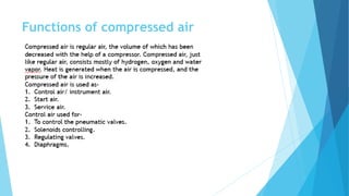
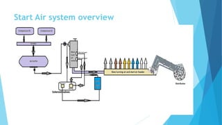
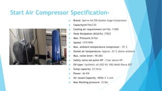
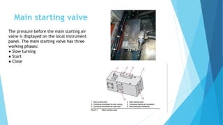
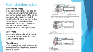
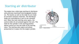
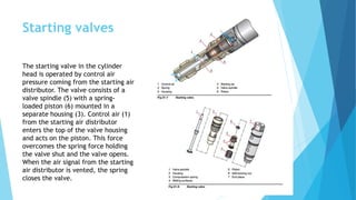
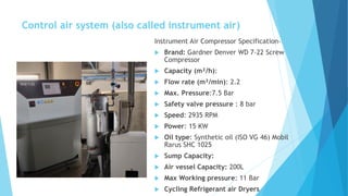
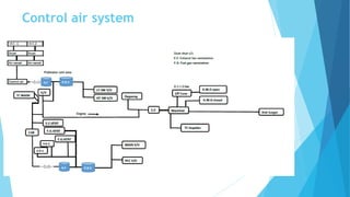
Compressed Air system
Dipongkar Saha.
Functions of compressed air
Starting Air System
The engine is started with a direct injection of compressed air through the
starting valves into the cylinders.
The starting air system consists of:
● Main starting valve. The main starting valve is a combined starting and slow
turning valve.
● Starting air distributor
● Starting valves
● Starting air vessel and piping (external system).
Start Air system overview
Start Air Compressor Specification-
 Brand: Sperre XA 250 double stage Compressor
 Capacity(m³/h):230
 Cooling air requirement (m³/h): 11000
 Heat dissipation (kCal/h): 37822
 Max. Pressure:30 Bar
 Speed: 1475 RPM
 Max. ambient temperature compressor : 55°C
 Outlet air temperature: Approx. 25°C above ambient
 Max. noise level : 98 dBA
 Safety valve set point HP : 3 bar above HP
 Oil type: Synthetic oil (ISO VG 100) Mobil Rarus 827
 Sump capacity: 23 litres
 Power: 46 KW
 Air vessel Capacity: 4800L X 3 unit
 Max Working pressure: 33 Bar
Main starting valve
The pressure before the main starting air
valve is displayed on the local instrument
panel. The main starting valve has three
working phases:
● Slow turning
● Start
● Close
Main starting valve
Slow turning Phase
In the slow turning phase, the pilot air
(1) moves the twin piston (3) so that the
slow turning circuit is open. The starting
air master valve has an integrated
throttle valve (4) for adjusting the slow
turning speed. Two full revolutions
should take 5-6 seconds. This ensures
that the slow turning speed is
appropriate for all starting conditions.
Start Phase
In the start phase, the pilot air (1)
pushes the hollow piston and the
start air flows freely.
Closed Phase
In the closed phase, there is no pilot air
and the valve breathes freely. The main
air line is closed
Starting air distributor
The engine has a slide-type starting air distributor
with precision-machined interchangeable bushes
(3). The bushes as well as the slide (5) are made
of corrosion-resistant materials. The distributor
slides are controlled by a cam at the camshaft
end. When the main starting valve opens, the
control slides (5) are pressed against the cam. The
slide for the cylinder in the starting position
admits control air into the slide of the starting
valve. The starting valve opens and allows
pressurized air to pass into the engine cylinder.
Starting valves
The starting valve in the cylinder
head is operated by control air
pressure coming from the starting air
distributor. The valve consists of a
valve spindle (5) with a spring-
loaded piston (6) mounted in a
separate housing (3). Control air (1)
from the starting air distributor
enters the top of the valve housing
and acts on the piston. This force
overcomes the spring force holding
the valve shut and the valve opens.
When the air signal from the starting
air distributor is vented, the spring
closes the valve.
Control air system (also called instrument air)
Instrument Air Compressor Specification-
 Brand: Gardner Denver WD 7-22 Screw
Compressor
 Capacity (m³/h):
 Flow rate (m³/min): 2.2
 Max. Pressure:7.5 Bar
 Safety valve pressure : 8 bar
 Speed: 2935 RPM
 Power: 15 KW
 Oil type: Synthetic oil (ISO VG 46) Mobil
Rarus SHC 1025
 Sump Capacity:
 Air vessel Capacity: 200L
 Max Working pressure: 11 Bar
 Cycling Refrigerant air Dryers
Compressor operating Instructions
 Turn the main switch to ON position.
 If there are alarms, press the controller's RESET button until all are confirmed.
 Stop the compressor at least for 10 minutes before checking the oil level.
 Check delivery valve and other valves in order.
 Air dryer ON
 Press the START button.
 Check all parameter
 Check Air vessel condensate line activate?
 Adjust the Unload and Load pressure values if required. The recommended
pressure difference between the Load and Unload pressures is 1 bar.
 Too small pressure difference causes foaming of the oil. This increases the oil
consumption and wearing of the components.
 The Unload pressure cannot be adjusted higher than the compressor’s allowed
maximum pressure
MAINTENANCE OF COMRPESSORS
 Do not fill oil between oil changes without knowing the reason for the oil
consumption. When oil is needed it is recommended to make log with the
amount and type of oil filled. Never mix oil types.
 The compressor needs to be started minimum once a week and to run for one
hour to secure that all water condensate in the oil system is evaporated.
 Before starting the compressor after a week stand still, open the oil drain plug
and check that no water is detected in the oil reservoir. If water is found drain it
out before starting the compressor.
 The running temperature of the compressor must be minimum 50°C above the
cooling media.
 Oil change must be done at 1500 running hours or at least every second year
whichever occurs first.
Control air system
HT & LT 3 way valve
 The main task of control air system is
to supply all pneumatic devices with
dry, good quality air at a constant 4 -7
bar pressure.
 The positioner transducer to the
control system or device that will
command the valve's position. This
could be a 4-20mA signal depending on
the transducer's specifications and
compatibility with your control system.
 Ensure that the air supply is dry,
filtered, and at a suitable temperature
to prevent any adverse effects on the
performance of the positioner
transducer.
LT 3- way valve HT 3- way valve
Air Waste Gate/Anti surge
 The air waste gate, the charge air pressure is
controlled by a butterfly valve, which in turn is
controlled by an I/P converter. The anti-surge
device is used to prevent the turbocharger
compressor from surging and the engine from
stalling in sudden load drops and frequent grid trips
by relieving pressurized air from the charge air
system to the exhaust system. During fast and
sufficiently large load drops at higher loads
(>~50%), the solenoid valve is energized and the
butterfly valve opens briefly.
 Air is supplied to the I/P converter and the
positioner in the actuator unit. The I/P converter
supplies a 0.2-1.0 bar control air pressure to the
positioner depending on the incoming 4-20 mA
control signal. The positioner pilot valve supplies
the actuator with air pressure according to the
control air pressure from the I/P converter.
Anti Surge device/Air waste gate
 The butterfly valve opens when the
charge air pressure is above and the
ambient temperature is below the set
values.
 The turbocharger pumps more air into
the cylinder at lower suction air
temperature causing the air pressure
in the air receiver to increase the
firing pressure.
 The air waste gate limits the charge
air pressure by releasing some of the
charge air back to the atmosphere.
This protects the engine from too high
firing pressure and turbocharger surge.
TC Impeller Cooling valve
 NT1-12 turbocharger higher rotor speed results in
higher compressor temperatures and would
consequently reduce the life of the impeller
were it not for the inclusion of an impeller
cooling valve.
 NT1-12 is fitted with an impeller cooling valve
that actuates at a trigger speed of 24,600rpm.
When the impeller cooling valve is switched on,
it allows cooling air to flow down the back of the
impeller thus keeping it operating within the
required temperature limits.
 The impeller cooling valve is fitted either side of
the main casing. It requires a compressed air
source to move the cooling control piston and a
3-way solenoid valve to control the start and end
of cooling as determined by the rotor speed to
achieve the required operating life of 50,000
hours the NT1-12
 below 24,600rpm there is no requirement for
cooling
 at 24,600rpm and above the impeller will require
cooling
Exhaust Gas venting
 The exhaust gases produced by the gas engine are
collected at the engine's exhaust manifold or exhaust
outlet. These gases contain various by products of
combustion, such as carbon dioxide, nitrogen oxides,
carbon monoxide, and particulate matter.
 exhaust gases are drawn into the fan, they are forced
through the exhaust fan housing and ductwork. The
fan's design and blades help in directing the gases in
the desired direction, usually towards an exhaust
stack or chimney.
 The operation of the exhaust fan in a gas engine
exhaust line can be controlled manually or through
automated systems. Control mechanisms may include
switches, sensors, or programmable logic controllers
(PLCs) that activate the fan based on engine
operating conditions, temperature thresholds, or
other relevant factors.
Gas Degassing
CGR unit
Thank you for being patience during
Training season!!!
Do you have any question???

Compressed Air system.pdf

  • 1.
  • 2.
  • 3.
    Starting Air System Theengine is started with a direct injection of compressed air through the starting valves into the cylinders. The starting air system consists of: ● Main starting valve. The main starting valve is a combined starting and slow turning valve. ● Starting air distributor ● Starting valves ● Starting air vessel and piping (external system).
  • 4.
  • 5.
    Start Air CompressorSpecification-  Brand: Sperre XA 250 double stage Compressor  Capacity(m³/h):230  Cooling air requirement (m³/h): 11000  Heat dissipation (kCal/h): 37822  Max. Pressure:30 Bar  Speed: 1475 RPM  Max. ambient temperature compressor : 55°C  Outlet air temperature: Approx. 25°C above ambient  Max. noise level : 98 dBA  Safety valve set point HP : 3 bar above HP  Oil type: Synthetic oil (ISO VG 100) Mobil Rarus 827  Sump capacity: 23 litres  Power: 46 KW  Air vessel Capacity: 4800L X 3 unit  Max Working pressure: 33 Bar
  • 6.
    Main starting valve Thepressure before the main starting air valve is displayed on the local instrument panel. The main starting valve has three working phases: ● Slow turning ● Start ● Close
  • 7.
    Main starting valve Slowturning Phase In the slow turning phase, the pilot air (1) moves the twin piston (3) so that the slow turning circuit is open. The starting air master valve has an integrated throttle valve (4) for adjusting the slow turning speed. Two full revolutions should take 5-6 seconds. This ensures that the slow turning speed is appropriate for all starting conditions. Start Phase In the start phase, the pilot air (1) pushes the hollow piston and the start air flows freely. Closed Phase In the closed phase, there is no pilot air and the valve breathes freely. The main air line is closed
  • 8.
    Starting air distributor Theengine has a slide-type starting air distributor with precision-machined interchangeable bushes (3). The bushes as well as the slide (5) are made of corrosion-resistant materials. The distributor slides are controlled by a cam at the camshaft end. When the main starting valve opens, the control slides (5) are pressed against the cam. The slide for the cylinder in the starting position admits control air into the slide of the starting valve. The starting valve opens and allows pressurized air to pass into the engine cylinder.
  • 9.
    Starting valves The startingvalve in the cylinder head is operated by control air pressure coming from the starting air distributor. The valve consists of a valve spindle (5) with a spring- loaded piston (6) mounted in a separate housing (3). Control air (1) from the starting air distributor enters the top of the valve housing and acts on the piston. This force overcomes the spring force holding the valve shut and the valve opens. When the air signal from the starting air distributor is vented, the spring closes the valve.
  • 10.
    Control air system(also called instrument air) Instrument Air Compressor Specification-  Brand: Gardner Denver WD 7-22 Screw Compressor  Capacity (m³/h):  Flow rate (m³/min): 2.2  Max. Pressure:7.5 Bar  Safety valve pressure : 8 bar  Speed: 2935 RPM  Power: 15 KW  Oil type: Synthetic oil (ISO VG 46) Mobil Rarus SHC 1025  Sump Capacity:  Air vessel Capacity: 200L  Max Working pressure: 11 Bar  Cycling Refrigerant air Dryers
  • 11.
    Compressor operating Instructions Turn the main switch to ON position.  If there are alarms, press the controller's RESET button until all are confirmed.  Stop the compressor at least for 10 minutes before checking the oil level.  Check delivery valve and other valves in order.  Air dryer ON  Press the START button.  Check all parameter  Check Air vessel condensate line activate?  Adjust the Unload and Load pressure values if required. The recommended pressure difference between the Load and Unload pressures is 1 bar.  Too small pressure difference causes foaming of the oil. This increases the oil consumption and wearing of the components.  The Unload pressure cannot be adjusted higher than the compressor’s allowed maximum pressure
  • 12.
    MAINTENANCE OF COMRPESSORS Do not fill oil between oil changes without knowing the reason for the oil consumption. When oil is needed it is recommended to make log with the amount and type of oil filled. Never mix oil types.  The compressor needs to be started minimum once a week and to run for one hour to secure that all water condensate in the oil system is evaporated.  Before starting the compressor after a week stand still, open the oil drain plug and check that no water is detected in the oil reservoir. If water is found drain it out before starting the compressor.  The running temperature of the compressor must be minimum 50°C above the cooling media.  Oil change must be done at 1500 running hours or at least every second year whichever occurs first.
  • 13.
  • 14.
    HT & LT3 way valve  The main task of control air system is to supply all pneumatic devices with dry, good quality air at a constant 4 -7 bar pressure.  The positioner transducer to the control system or device that will command the valve's position. This could be a 4-20mA signal depending on the transducer's specifications and compatibility with your control system.  Ensure that the air supply is dry, filtered, and at a suitable temperature to prevent any adverse effects on the performance of the positioner transducer. LT 3- way valve HT 3- way valve
  • 15.
    Air Waste Gate/Antisurge  The air waste gate, the charge air pressure is controlled by a butterfly valve, which in turn is controlled by an I/P converter. The anti-surge device is used to prevent the turbocharger compressor from surging and the engine from stalling in sudden load drops and frequent grid trips by relieving pressurized air from the charge air system to the exhaust system. During fast and sufficiently large load drops at higher loads (>~50%), the solenoid valve is energized and the butterfly valve opens briefly.  Air is supplied to the I/P converter and the positioner in the actuator unit. The I/P converter supplies a 0.2-1.0 bar control air pressure to the positioner depending on the incoming 4-20 mA control signal. The positioner pilot valve supplies the actuator with air pressure according to the control air pressure from the I/P converter.
  • 16.
    Anti Surge device/Airwaste gate  The butterfly valve opens when the charge air pressure is above and the ambient temperature is below the set values.  The turbocharger pumps more air into the cylinder at lower suction air temperature causing the air pressure in the air receiver to increase the firing pressure.  The air waste gate limits the charge air pressure by releasing some of the charge air back to the atmosphere. This protects the engine from too high firing pressure and turbocharger surge.
  • 17.
    TC Impeller Coolingvalve  NT1-12 turbocharger higher rotor speed results in higher compressor temperatures and would consequently reduce the life of the impeller were it not for the inclusion of an impeller cooling valve.  NT1-12 is fitted with an impeller cooling valve that actuates at a trigger speed of 24,600rpm. When the impeller cooling valve is switched on, it allows cooling air to flow down the back of the impeller thus keeping it operating within the required temperature limits.  The impeller cooling valve is fitted either side of the main casing. It requires a compressed air source to move the cooling control piston and a 3-way solenoid valve to control the start and end of cooling as determined by the rotor speed to achieve the required operating life of 50,000 hours the NT1-12  below 24,600rpm there is no requirement for cooling  at 24,600rpm and above the impeller will require cooling
  • 18.
    Exhaust Gas venting The exhaust gases produced by the gas engine are collected at the engine's exhaust manifold or exhaust outlet. These gases contain various by products of combustion, such as carbon dioxide, nitrogen oxides, carbon monoxide, and particulate matter.  exhaust gases are drawn into the fan, they are forced through the exhaust fan housing and ductwork. The fan's design and blades help in directing the gases in the desired direction, usually towards an exhaust stack or chimney.  The operation of the exhaust fan in a gas engine exhaust line can be controlled manually or through automated systems. Control mechanisms may include switches, sensors, or programmable logic controllers (PLCs) that activate the fan based on engine operating conditions, temperature thresholds, or other relevant factors.
  • 19.
  • 20.
  • 21.
    Thank you forbeing patience during Training season!!! Do you have any question???