Comparative study of gfrp laminated rc column using experimental results and isis canada
•
1 like•383 views

IJRET : International Journal of Research in Engineering and Technology is an international peer reviewed, online journal published by eSAT Publishing House for the enhancement of research in various disciplines of Engineering and Technology. The aim and scope of the journal is to provide an academic medium and an important reference for the advancement and dissemination of research results that support high-level learning, teaching and research in the fields of Engineering and Technology. We bring together Scientists, Academician, Field Engineers, Scholars and Students of related fields of Engineering and Technology

Recommended
Recommended
More Related Content
Viewers also liked
Viewers also liked (20)
More from eSAT Publishing House
More from eSAT Publishing House (20)
Recently uploaded
Recently uploaded (20)
Comparative study of gfrp laminated rc column using experimental results and isis canada
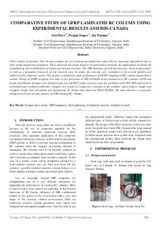
- 1. IJRET: International Journal of Research in Engineering and Technology eISSN: 2319-1163 | pISSN: 2321-7308 _______________________________________________________________________________________ Volume: 03 Issue: 04 | April-2014, Available @ http://www.ijret.org 700 COMPARATIVE STUDY OF GFRP LAMINATED RC COLUMN USING EXPERIMENTAL RESULTS AND ISIS-CANADA Atri Dave 1 , Poojan Nagar 2 , Jay Parmar 3 1 Student, Civil Engineering, Gandhinagar Institute of Technology, Gujarat, India 2 Student, Civil Engineering, Gandhinagar Institute of Technology, Gujarat, India 3 Assistant Professor Civil Engineering, Indus University, Gujarat, India Abstract Fibre reinforced polymers have become popular for civil engineering application especially for structural upgradation due to their sound engineering properties. These materials have been found to be particularly attractive for applications involving the strengthening and rehabilitation of reinforced concrete structure. The FRP laminates provide the necessary hoop reinforcement, as well as a permanent formwork for the concrete core. In return, the concrete core contributes to the overall stability and stiffness of the composite system. This project is intended to study performance of GFRP wrapping on RC column representative sample. Design of GFRP wrapping was done as per provisions in ISIS-CANADA design manual no.4. RC cylinders of 600 mm height and 200 mm diameter were designed and cast with M25 grade concrete as per the guidelines of IS:456-2000 and tested in unconfined and confined conditions, compare test results of compressive strength of the ordinary representative sample and wrapped sample also calculating and analogizing the design steps based on ISIS-CANADA. The main objective is to predict ultimate axial load carrying capacity of FRP confined RC columns Key Words: Comparative study; FRP laminates; Strengthening; Confined concrete; Analytical study --------------------------------------------------------------------***---------------------------------------------------------------------- 1. INTRODUCTION Over the last few years, there has been a worldwide increase in the use of composite materials for the rehabilitation of deficient reinforced concrete (RC) structures. One important application of this composite retrofitting technology is the use of fibre reinforced polymer (FRP) jackets or sheets to provide external confinement to RC columns when the capacity of existing structure is inadequate. RC columns need to be laterally confined in order to ensure large deformation under load before failure and to provide an adequate load resistance capacity. In the case of a seismic event, energy dissipation allowed by a well-confined concrete core can often save lives. On the contrary, a poorly confined concrete column behaves in a brittle manner, leading to sudden and catastrophic failures. Use of externally bonded FRP composite for strengthening can be a cost effective alternative for upgrading the performance of existing RC columns. More research work is been carried out analysing on the flexural behaviour of RC beams, efficiency of FRP confinement related to the radius of the cross-section edges, size and shape of the concrete column cross-section. Thus six reinforced concrete column specimens were casted and wrapped and unwrapped samples were tested in order to get the experimental results. Different country has formulated different types of design steps to find out the compressive strength. The design of the fibre composite system was done as per the guide lines from ISIS- Canada fibre wrap manual no.-4.The analytical results were derived as per guidelines of ISIS-Canada and thus these results were compared with the experimental results. Thus verifying the design steps mentioned in the fibre wrap manual. 2. EXPERIMENTAL PROGRAM 2.1 Reinforcement details Steel cage with main steel 6-12mm∅ of grade Fe-415, lateral ties of 3-8mm∅ @ 190mm with lateral tie ring diameter 150mm. Fig1 (a) Steel Cage (b) 8mm Circular Steel Tie
- 2. IJRET: International Journal of Research in Engineering and Technology eISSN: 2319-1163 | pISSN: 2321-7308 _______________________________________________________________________________________ Volume: 03 Issue: 04 | April-2014, Available @ http://www.ijret.org 701 2.2 Concrete mix Concrete machine mix of M25 grade was prepared as per provision in IS: 456-2000 using 53 grade cement, sand and fine and course aggregates. Proportion of material as per volumetric batch was CSA – 1:1:2.Immediate slump test results showed a true slump of 80 mm using standard slump cone. Water cement ratio was maintained 0.55. Table 1.Concrete Mix Properties Material Volume(m^3) Volumetric Proportion Water 0.040 0.184 Cement 0.053 0.244 Sand 0.053 0.244 Aggregate mix 0.071 0.327 Total 0.217 ~1.00 2.3 Casting of RC column The respective column representative sample were cast of pre-decided dimensions using PVC pipe as a formwork of diameter 210mm and 600mm high, the column representative sample of dimensions 200mm diameter and 600mm height was obtained. The pipes were erected on the back side of the flat and leveled shuttering panel to obtain finished bottom and in order to reduce loss of water from concrete empty cement bags were laid between pipe and panel. Cover of 25mm was provided. Fig2. (a) PVC Pipe (b) Casting Arrangement 2.4 Fibre properties The properties of GFRP sheet are presented in Table 2. The resin system used to bond the glass fabrics over the columns is an epoxy resin made of two parts, resin and hardener. Fig. 3 shows GFRP sheet in roll form and defines the direction of layer of fibre which is more in longitudinal direction as compared to the transverse direction. Table 2.GFRP Properties Supplied by Manufacturer Sikawrap-100 G/45: Fibre weight(g/𝒎 𝟐 ) Sheet width(mm) Fibre thickness(mm) 935 600 0.358 Ultimate tensile strength(MPa) Elastic modulus(MPa) Ultimate elongation(%) 3400 76,000 2.8 Fig.3. GFRP (a) Sheet Roll (b) Unidirectional Sheet 2.5 Wrapping of columns The concrete surface needed to be cleaned with wire brush to remove all the loose dust particles. Primer coats were applied over the concrete surface. Epoxy resin mix was made from the two different parts i.e. base and hardener. They were taken in equal proportion and mixed together. Epoxy resin mix was applied over the surface with hand brush. After application of the epoxy resin mix a pre-cut GFRP sheet were wrapped around the columns with the help of tamping brush and roller. The fibres were impregnated with epoxy resin mix in order to achieve complete confinement. The air pockets were removed with the help roller. Fig 4 (a) Application of Mix on the Clean Substrate (b)Application of Fibre Cloth (c) Impregnating the Fibre with Resin Mix
- 3. IJRET: International Journal of Research in Engineering and Technology eISSN: 2319-1163 | pISSN: 2321-7308 _______________________________________________________________________________________ Volume: 03 Issue: 04 | April-2014, Available @ http://www.ijret.org 702 2.6 Test setup The Uniaxial compression load test on the Column representative sample was performed with the help of digital Universal Testing Machine (UTM) of 1000kN capacity having a least count of 0.01kN, applying Uniaxial loading at 7.33kN/minute of rate of loading, to the sample placed in vertical orientation to the loading plates. An arrangement was made in order to get the Axial deflection in the samples with the help of magnetic pole and dial gauge. Needle of the dial gauge was rested on hydraulic drum such that change in length of column and vertical movement of the hydraulic drum is equal. The column sample was subjected to compressive load up to failure and the respective observation values were recorded as under 3. Results and discussion 3.1 Analytical study According to IS:456-2000 the ultimate load carrying capacity of the unconfined column specimen was found to be 495.80 kN Thus the test results obtained for unconfined specimens were quite satisfactory. The bonding of FRP sheets, where the fibre orientation is perpendicular to the column axis to limit the circumferential strains in the column, constitutes confinement. The ultimate confinement pressure due to FRP strengthening „𝑓𝑙𝑓𝑟𝑝 ‟ may be determined as: 𝑓𝑙𝑓𝑟𝑝 = 2𝑁 𝑏 ∅ 𝑓𝑟𝑝 𝑓 𝑓𝑟𝑝𝑢 𝑡 𝑓𝑟𝑝 𝐷 𝑔 = 6.64MPa For a continuous confinement, the volumetric ratio of the FRP strength to the concrete strength is defined as: ɷ 𝑤 = 2𝑓 𝑙𝑓𝑟𝑝 ∅ 𝑐 𝑓´ 𝑐 = 0.88 The compressive strength of the confined concrete 𝑓′ 𝑐𝑐 is determined from the following equation: 𝑓´ 𝑐𝑐 =𝑓´ 𝑐(1+𝛼 𝑝𝑐 ɷ 𝑤 ) = 47MPa The performance coefficient for a circular column „𝛼 𝑝𝑐 ‟, depends on the FRP stiffness and ultimate strain, the concrete strength, the quality of application and the fibre- resin-concrete bond. In view of the limited test data currently available, a Coefficient „𝛼 𝑝𝑐 ‟ of 1.0 is suggested at the present time. The factored axial load resistance „𝑝𝑟𝑚𝑎𝑥 ‟ for a confined column is given by the following equation: 𝑝𝑟𝑚𝑎𝑥 =ke [𝛼1(∅ 𝑐)(𝑓´ 𝑐𝑐 )(𝐴 𝑔 − 𝐴 𝑐) + ∅ 𝑠(𝑓𝑦 )(𝐴 𝑠𝑡)]= 792.48kN ‘𝑘 𝑒’ is a strength reduction factor applied for unexpected eccentricities and „𝛼1‟ the ratio of average stress in the rectangular compression block to the specified concrete strength. Hence, the analytical calculations show that the compressive strength of the column member increases after confinement by GFRP wrap. 3.2 Failure Modes and Crack patterns The confined concrete strength is essentially dependent on the maximum confining pressure that the FRP can apply. The FRP confinement increases the axial load carrying capacity of concrete structures.Failure of column was not due to debonding of the GFRP laminate. It can be seen that cracks are developed inside the concrete core. On one of the sample slight rupture of the laminate was observed. At the top of the column glass fibre were seen disturbed after loading. The gradual failure of the confined columns with the sign of debonding at the top and middle half section is desirable from viewpoint of structural integrity. 3.3 Ultimate load carrying capacity GFRP wrapping for circular columns were expected to increase the axial load carrying capacity by 59.83% as per Fig. 5. Laboratory Test Setup for Uniaxial loading of Columns Fig 6. (a) Cracks developed with in the Concrete Core (b) Slight Rupture of Glass Fibres (c) Failure due to Core Cracking and not Delamination
- 4. IJRET: International Journal of Research in Engineering and Technology eISSN: 2319-1163 | pISSN: 2321-7308 _______________________________________________________________________________________ Volume: 03 Issue: 04 | April-2014, Available @ http://www.ijret.org 703 provisions in fibre manual by ISIS-Canada. The increase of 72.25% in axial load carrying capacity of specimen was observed when actual experiment was performed. The increment in analytical values was found comparatively low because of strength reduction factor of 0.85 applied for unexpected eccentricities to the final equation. Again the performance coefficient for a circular column „αpc’ depends on the FRP stiffness and ultimate strain, the concrete strength, the quality of application and the fibre-resin- concrete bond. In view of the limited test data currently available, a coefficient „αpc’ of 1.0 was suggested at the present time. Perhaps due to unavailability of accurate data this error might have aggregated. Fig 7. Ultimate Failure load for columns 3.4 Axial deformation Load vs. axial deformation behaviour for all columns is presented in Fig. 7. This gives information that confined specimens can undergo large deformations along with higher load carrying capacity. Also the significant improvement of ductile property was noticed. Also it can be seen that the confined specimen have rather more stability in terms of load carrying capacity as can be noticed by respective deformations. The curve generated for confined sample is much smoother than that of the unconfined samples. Fig 7. Load vs. Deformation Behavior for Columns 3.5 Axial Stress vs. Axial Strain Axial strain for columns was calculated from vertical deformation measured from dial gauge. Axial stress for columns was calculated as load divided by cross sectional area. Average axial strain was evaluated from average axial deformation for the columns. Modulus of elasticity was found out for linear elastic zone coordinates in both the curves by calculating the slope for that coordinates on the respective curves. It was observed that for all points on curve the improvement in modulus of elasticity was not significant. Thus it can be concluded that confinement of circular columns does not contribute much to the elastic property of the reinforced concrete. Fig 8. Axial Stress vs. Axial Strain Behaviour for Columns 4. Conclusion The confined concrete strength is essentially dependent on the maximum confining pressure that the FRP can apply. The FRP confinement increases the axial load carrying capacity of concrete structures. The increase of 72.25% axial load carrying capacity of specimen was observed after confinement. The gradual failure of the confined columns with the sign of debonding of glass fibre at the top and middle half section is desirable from viewpoint of structural integrity. The confinement of circular columns does not contribute much to the elastic property of the reinforced concrete rather it enhances more the ductility and stability of the reinforced concrete. It can be seen that the experimental values obtained were having minimum error and the design steps are safe enough to be executed even in Indian climatic conditions with good workmanship in regular practice. 5. Acknowledgements We are primarily thankful to Mr. Vijay Shah, Bhoomi Consultants, for his recommendation of area of research. We are thankful to Shree Ideas Unlimited for providing us the material and permission to cast the specimens on their site. We acknowledge Mr. Rumit Parikh,Vihan Techno Solutions for providing GFRP material as well as manpower for wrapping of columns. Our sincere thanks are to Mr. Nilesh Anandjiwala, AERI 509 876 495.8 792.48 0 200 400 600 800 1000 UCC CCC Axial Load (kN) Experimental Analytical 0 200 400 600 800 1000 0 2 4 6 8 10 AxialLoad(kN) Axial Deformation(kN) UCC CCC 0 10 20 30 0 0.005 0.01 0.015 0.02 Axialstress Axial strain CCC UCC
- 5. IJRET: International Journal of Research in Engineering and Technology eISSN: 2319-1163 | pISSN: 2321-7308 _______________________________________________________________________________________ Volume: 03 Issue: 04 | April-2014, Available @ http://www.ijret.org 704 laboratory for providing us the recommendation to perform tests in National Council of Cement and Building Materials under his supervision. We are also thankful to Mr. Tejas Parikh, EIE Instruments Pvt. Ltd. for providing us the necessary instruments for deflection check. 6. References 1. Indian Standard - IS : 456-2000 for RCC Short Column Design. 2. ISIS CANADA - Design Manual No. 4, September 2001, “Strengthening Reinforced Concrete Structures with Externally-Bonded Fibre Reinforced Polymers”. 3. Canadian Code - A23.3-94 (CSA 1994) 4. ACI 440.2R-08, Reported by ACI Committee 440 – “Guide for the Design and Construction of Externally Bonded FRP Systems for Strengthening Concrete Structures”. 5. M. Reza Ehsaniand M. Reza Kianoush.“AXIAL COMPRESSIVE STRENGTH OF REINFORCED CONCRETE COLUMNS WRAPPED WITH FIBRE REINFORCED POLYMERS (FRP)”. 6. Hamid Saadatmanesh, Mohammad R. Ehsani, and Limin Jin Technical Paper no. 94-S20 “Repair of Earthquake-Damaged RC Columns with FRP Wraps”. 7. FIB - Féd. Int. du Béton, 2001Externally Bonded FRP Reinforcement for RC Structures: Technical Report on the Design and Use of Externally Bonded Fibre Reinforced Polymer Reinforcement (FRP EBR) for Reinforced Concrete Structures 8. CPWD, Govt. of India, New Delhi, Handbook on Repair and Rehabilitation of RCC Structures. 9. Muhammad N.S. Hadi,Volume 74, Issue 2, July 2006,Composite Structures. 10. Huang Gu, Volume 27, Issue 7, 2006,Materials & Design. 11. Rahul Raval and Urmil Dave, Procedia Engineering, Volume 51, 2013, Pages 240–249, “Behavior of GFRP Wrapped RC Columns of Different Shapes”, 12. Tarek H. Almusallam, Composites Part B: Engineering, Volume 38, Issues 5–6, July–September 2007, “Behavior of normal and high-strength concrete cylinders confined with E-glass/epoxy composite laminates”.