ELH – 3.1: ADVANCED DIGITAL COMMUNICATION UNIT – II Coding techniques
1. ELH – 3.1: ADVANCED DIGITAL COMMUNICATION UNIT – II
1
Notes by Mr. Chandrakantha T S, Dept.t of PG Studies & Research in Electronics Kuvempu University, Jnanasahyadri, Shankaraghatta,2023-24
UNIT – II
Coding Techniques
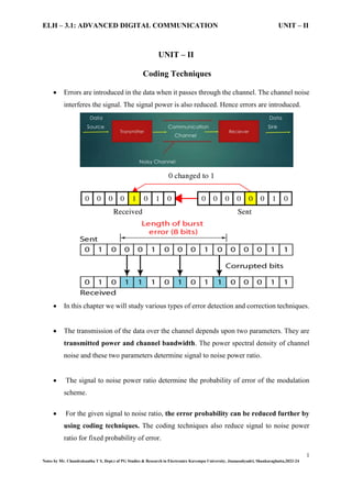
Errors are introduced in the data when it passes through the channel. The channel noise
interferes the signal. The signal power is also reduced. Hence errors are introduced.
In this chapter we will study various types of error detection and correction techniques.
The transmission of the data over the channel depends upon two parameters. They are
transmitted power and channel bandwidth. The power spectral density of channel
noise and these two parameters determine signal to noise power ratio.
The signal to noise power ratio determine the probability of error of the modulation
scheme.
For the given signal to noise ratio, the error probability can be reduced further by
using coding techniques. The coding techniques also reduce signal to noise power
ratio for fixed probability of error.
2. ELH – 3.1: ADVANCED DIGITAL COMMUNICATION UNIT – II
2
Notes by Mr. Chandrakantha T S, Dept.t of PG Studies & Research in Electronics Kuvempu University, Jnanasahyadri, Shankaraghatta,2023-24
Coding techniques play a crucial role in information transmission and storage systems,
enhancing reliability and efficiency.
One prominent approach is convolutional coding, a method widely used in digital
communication systems to add redundancy to data for error detection and correction.
Error Control Coding
Error control coding is a crucial aspect of digital communication systems, aiming to
detect and correct errors introduced during data transmission.
Redundancy bits are added to the original data to create a codeword, providing the
receiver with the means to identify and correct errors.
This process involves encoding at the transmitter and decoding at the receiver.
Channel Encoding
Channel encoding involves the addition of redundant information to the original data
before transmission, allowing for the detection and correction of errors at the receiver.
3. ELH – 3.1: ADVANCED DIGITAL COMMUNICATION UNIT – II
3
Notes by Mr. Chandrakantha T S, Dept.t of PG Studies & Research in Electronics Kuvempu University, Jnanasahyadri, Shankaraghatta,2023-24
Convolutional codes are one type of channel encoding technique. In a convolutional
encoder, input data is processed continuously, and the output is a coded sequence with
controlled redundancy.
Channel Decoding
Channel decoding is the process of reconstructing the original data at the receiver by
utilizing the redundant information added during encoding.
For convolutional codes, the Viterbi algorithm is a widely used decoding technique.
It involves traversing the trellis diagram to find the most likely path that corresponds to
the transmitted sequence.
Advantages of Coding Technique
1. Improved Transmission Efficiency:
Optimized Data Representation: Coding enhances data representation for
efficient use of available bandwidth.
Fast Encoding and Decoding: Efficient algorithms contribute to quicker
transmission rates, enabling more data transfer within a given timeframe.
2. Reduced Probability of Error and Error Correction:
Redundancy for Error Detection: Coding introduces redundancy for effective
error detection.
4. ELH – 3.1: ADVANCED DIGITAL COMMUNICATION UNIT – II
4
Notes by Mr. Chandrakantha T S, Dept.t of PG Studies & Research in Electronics Kuvempu University, Jnanasahyadri, Shankaraghatta,2023-24
Automatic Error Correction: Error correction codes automatically fix errors
during transmission, ensuring data integrity and reducing the probability of
errors.
3. Optimized Transmitted Power and Channel Bandwidth:
Minimized Transmission Power: Coding minimizes the required power for
transmission while maintaining reliability.
Bandwidth Efficiency: Carefully designed codes make effective use of
frequency spectrum, allowing for increased data transmission within allocated
bandwidth.
4. Signal-to-Noise Power Ratio Improvement:
Noise Combat: Coding techniques are designed to combat channel noise,
enhancing the signal-to-noise power ratio.
Distinguishing Signal from Noise: Error correction codes help distinguish the
actual signal from noise, improving overall data transmission reliability.
5. Reduction in Signal-to-Noise Power for Fixed Probability of Error:
Lower Signal-to-Noise Ratio: Coding allows achieving a lower signal-to-noise
power ratio for a fixed probability of error.
Robust Code Design: Careful code design enhances signal robustness,
enabling reliable communication even in the presence of noise.
Convolutional Encoding
Convolutional encoding is a powerful error-correcting technique employed in digital
communication systems to enhance the reliability of data transmission.
Unlike block codes, which operate on fixed-sized blocks of data, convolutional codes
process data in a continuous manner.
This approach is particularly advantageous in scenarios where the data stream is
continuous, such as in wireless communication, satellite communication, and digital
broadcasting.
5. ELH – 3.1: ADVANCED DIGITAL COMMUNICATION UNIT – II
5
Notes by Mr. Chandrakantha T S, Dept.t of PG Studies & Research in Electronics Kuvempu University, Jnanasahyadri, Shankaraghatta,2023-24
Convolutional Encoder Representation
The representation of a convolutional encoder through different methods:
i. Convolutional Encoder (Generator) Representation
ii. State Diagram
iii. Tree Diagram
iv. Trellis Diagram
i) Convolutional Encoder (Generator) Representation
A convolutional coding is done by combining the fixed number of input bits. The input
bits are stored in the fixed length shift register and they are combined with the help of
mod-2 adders.
This operation is equivalent to binary convolution and hence it is called convolutional
coding. This concept is illustrated with the help of simple example given below.
Operation
Whenever the message bit is shifted to position 'm', the new values of x1 and x2 are
generated depending upon in, ml and m2. ml and m2 store the previous two message
bits. The current bit is present in m. Thus we can write,
1 0 1 2
x m m m
and 2
2 0
x m m
The output switch first samples x1 and then x2. The shift register then shifts contents
of m 1 to m2 and contents of in to mi. Next input bit is then taken and stored in in.
Again x1 and x2 are generated according to this new combination m0, m1 and m2.
6. ELH – 3.1: ADVANCED DIGITAL COMMUNICATION UNIT – II
6
Notes by Mr. Chandrakantha T S, Dept.t of PG Studies & Research in Electronics Kuvempu University, Jnanasahyadri, Shankaraghatta,2023-24
The output switch then samples x1 then x2. Thus the output bit stream for successive
input bits will be, 1 2 1 2 1 2 1 2.................
X=x x x x x x x x and so on ...
Here note that for every input message bit two encoded output bits x1 and x2 are
transmitted. In other words, for a single message bit, the encoded codeword is two bits.
Example:
Parameters of Convolutional Codes
Convolutional codes are characterized by several parameters that define their properties and
behavior. Let's discuss the key parameters associated with convolutional codes.
1) (n, k, K):
n: The number of output bits per input bit. It represents the rate of the convolutional
code. If n = 1, it's a rate-1 code. If n > 1, it's a rate-n code.
k: The number of input bits that affect the generation of one output bit
K: Constraint length, which is the number of bits in the shift register (excluding the
current input bit). It's the span over which the encoder has memory.
7. ELH – 3.1: ADVANCED DIGITAL COMMUNICATION UNIT – II
7
Notes by Mr. Chandrakantha T S, Dept.t of PG Studies & Research in Electronics Kuvempu University, Jnanasahyadri, Shankaraghatta,2023-24
Example: A convolutional code with (n=2, k=1, K=3) means it is a rate-1/2 code with
a constraint length of 2.
2) Code Rate (r):
The code rate, denoted as k
r =
n
, represents the ratio of the number of
information bits (k) to the total number of bits in the encoded sequence (n).
It provides information about the efficiency of the code.
Example: If a convolutional code has k=1 and n=2, then the code rate is
1
r =
2
3) Constraint Length (L):
The constraint length (L) of a convolutional code is the total number of shift register
stages involved in the encoding process.
It is directly related to k and K, where
L=K× n
( -1)+k
Example: For a convolutional code with k=1 and K=3, the constraint length would be
L=3× (2−1) +1=4.
4) Dimension of the Code (m):
The dimension of a convolutional code, denoted as m, represents the number of states
in the Sate/trellis diagram.
The dimension is related to the number of shift register states and is given by
K
m = 2 , where K is the constraint length.
Example: If a convolutional code has a constraint length of K=3, the dimension would
be 3
m = 2 = 8 .
8. ELH – 3.1: ADVANCED DIGITAL COMMUNICATION UNIT – II
8
Notes by Mr. Chandrakantha T S, Dept.t of PG Studies & Research in Electronics Kuvempu University, Jnanasahyadri, Shankaraghatta,2023-24
Types of Convolutional Encoding
The types of convolutional encoding methods can be categorized into analytical methods and
graphical methods.
a) Analytical Method:
1. Time Domain Approach:
a. Convolutional Method:
This approach involves defining convolutional codes directly in the time domain. It focuses
on the shift register operations and feedback connections that generate the encoded sequence.
Types of Convolutional Encoding
a)Analytical Method
1. Time Domain
Approach
a.Convoutional
Method
b.Matrix
Generator
Method
2. Transform
Domain
Approach
b)Graphical Method
a)State Diagram
b)Code Tree
Diagram
c)Trellis
Diagram
9. ELH – 3.1: ADVANCED DIGITAL COMMUNICATION UNIT – II
9
Notes by Mr. Chandrakantha T S, Dept.t of PG Studies & Research in Electronics Kuvempu University, Jnanasahyadri, Shankaraghatta,2023-24
Problems:
10. ELH – 3.1: ADVANCED DIGITAL COMMUNICATION UNIT – II
10
Notes by Mr. Chandrakantha T S, Dept.t of PG Studies & Research in Electronics Kuvempu University, Jnanasahyadri, Shankaraghatta,2023-24
11. ELH – 3.1: ADVANCED DIGITAL COMMUNICATION UNIT – II
11
Notes by Mr. Chandrakantha T S, Dept.t of PG Studies & Research in Electronics Kuvempu University, Jnanasahyadri, Shankaraghatta,2023-24
b. Matrix Generator Method:
In this method, matrices are used to represent the connections and operations of the
convolutional encoder. The generator matrix is a key component, and it allows for a concise
representation of the encoding process.
12. ELH – 3.1: ADVANCED DIGITAL COMMUNICATION UNIT – II
12
Notes by Mr. Chandrakantha T S, Dept.t of PG Studies & Research in Electronics Kuvempu University, Jnanasahyadri, Shankaraghatta,2023-24
13. ELH – 3.1: ADVANCED DIGITAL COMMUNICATION UNIT – II
13
Notes by Mr. Chandrakantha T S, Dept.t of PG Studies & Research in Electronics Kuvempu University, Jnanasahyadri, Shankaraghatta,2023-24
2. Transform Domain Approach:
This approach involves representing convolutional codes in a transformed domain, such as the
frequency domain.
14. ELH – 3.1: ADVANCED DIGITAL COMMUNICATION UNIT – II
14
Notes by Mr. Chandrakantha T S, Dept.t of PG Studies & Research in Electronics Kuvempu University, Jnanasahyadri, Shankaraghatta,2023-24
15. ELH – 3.1: ADVANCED DIGITAL COMMUNICATION UNIT – II
15
Notes by Mr. Chandrakantha T S, Dept.t of PG Studies & Research in Electronics Kuvempu University, Jnanasahyadri, Shankaraghatta,2023-24
16. ELH – 3.1: ADVANCED DIGITAL COMMUNICATION UNIT – II
16
Notes by Mr. Chandrakantha T S, Dept.t of PG Studies & Research in Electronics Kuvempu University, Jnanasahyadri, Shankaraghatta,2023-24
b) Graphical Method:
1. State Diagram:
A state diagram is a graphical representation of a convolutional code. It illustrates the states of
the shift registers and the transitions between them based on the input symbols. Each state
represents a unique configuration of the shift registers.
17. ELH – 3.1: ADVANCED DIGITAL COMMUNICATION UNIT – II
17
Notes by Mr. Chandrakantha T S, Dept.t of PG Studies & Research in Electronics Kuvempu University, Jnanasahyadri, Shankaraghatta,2023-24
2. Code Tree Diagram:
The code tree diagram is another graphical representation that shows the paths through the
encoder for all possible input sequences. It provides a visual way to understand how the
encoding process evolves based on different inputs.
18. ELH – 3.1: ADVANCED DIGITAL COMMUNICATION UNIT – II
18
Notes by Mr. Chandrakantha T S, Dept.t of PG Studies & Research in Electronics Kuvempu University, Jnanasahyadri, Shankaraghatta,2023-24
3. Trellis Diagram:
The trellis diagram is a compact representation that combines elements of the state diagram
and the code tree. It visualizes the transitions between states for each input bit, allowing for an
efficient representation of the encoding process. The trellis diagram is particularly useful for
understanding and implementing the Viterbi algorithm for decoding.
19. ELH – 3.1: ADVANCED DIGITAL COMMUNICATION UNIT – II
19
Notes by Mr. Chandrakantha T S, Dept.t of PG Studies & Research in Electronics Kuvempu University, Jnanasahyadri, Shankaraghatta,2023-24
Formulation of the Convolutional Decoding Problem:
In convolutional coding, information bits are processed using convolutional encoders to
produce a coded sequence.
The convolutional decoding problem involves recovering the original information
bits from the received, possibly noisy, coded sequence.
This problem is typically solved using algorithms such as the Viterbi algorithm, which
searches for the most likely path through the trellis diagram representing the
convolutional code.
Properties of Convolutional Codes
1.Distance Property of Convolutional Codes
The distance properties of a convolutional code determine its ability to correct errors.
The minimum distance dmin of a code is defined as the smallest number of bit changes
required to convert one valid codeword into another.
Mathematically, it is expressed as min , (
, , )
j
i
c c ci cj
d min C HammingDistance ci cj
,whereC is the set of all valid codewords in the convolutional code.
For example, consider a convolutional code with two codewords C1=1101 and C2
=1010.
The Hamming distance between these codewords is
dmin=HammingDistance(1101,1010)=3, indicating that the minimum distance of the
code is 3.
2. Systematic Convolutional Codes
Systematic convolutional codes have a systematic encoder, which means that the
original data bits appear explicitly in the codeword.
The systematic form of a convolutional encoder is given by
)
c D
( ) ( )
= u ×g(
D D
where:
c(D) is the codeword polynomial,
20. ELH – 3.1: ADVANCED DIGITAL COMMUNICATION UNIT – II
20
Notes by Mr. Chandrakantha T S, Dept.t of PG Studies & Research in Electronics Kuvempu University, Jnanasahyadri, Shankaraghatta,2023-24
u(D) is the information polynomial,
g(D) is the generator polynomial.
For example, let u(D)=1011 and g(D)=1+D+D2. The systematic convolutional
codeword is obtained by polynomial multiplication
2 2
2 3 4 5 6
( ) ( ) ( ) (
c D = 1+ D+ D × 1+ D+ D × 1 )
+ D
=1+D+D +D +D +D +D
So, the systematic convolutional codeword is 1011110010, where the original data
bits 10111011 are explicitly present.
3.Nonsystematic Convolutional Codes
Nonsystematic convolutional codes do not have a systematic structure, and the encoded
bits may not be the same as the original data bits.
The encoder is a general polynomial multiplication )
c D
( ) ( )
= u ×g(
D D
where u(D) is the information polynomial and g(D) is the generator polynomial.
For example, let u(D)=1011 and g(D)=1+D+D2. The nonsystematic convolutional
codeword is obtained by polynomial multiplication
2 2
2 3 4 5 6
( ) ( ) ( ) (
c D = 1+ D+ D × 1+ D+ D × 1 )
+ D
=1+D+D +D +D +D +D
So, the nonsystematic convolutional codeword is also 11011101101110, but in this
case, the original data bits are not explicitly present in the codeword.
4. Performance Bounds for Convolutional Codes
Coding Gain(G): Coding gain is a measure of the improvement in performance achieved by
using error-correcting codes. It is defined as the difference in signal-to-noise ratio (SNR)
between the uncoded system and the coded system required to achieve a certain error rate.
10
coded
1
)
G = 10log
BER
( where BER is the bit error rate.
Example:
Let's assume the following:
Uncoded System BER (BERuncoded): 10−3
(1 in 1000 bits is in error).
Coded System BER (BEBERcoded): 10−5
(1 in 100,000 bits is in error).
21. ELH – 3.1: ADVANCED DIGITAL COMMUNICATION UNIT – II
21
Notes by Mr. Chandrakantha T S, Dept.t of PG Studies & Research in Electronics Kuvempu University, Jnanasahyadri, Shankaraghatta,2023-24
10 -5
5
10
1
G
0
(
1 )
= 0log
1
G =10log 10
G =10×5
G =50
( )
The coding gain, in this case, is 50 dB. This means that the coded system provides a 50 dB
improvement in signal-to-noise ratio (SNR) compared to the uncoded system for the same bit
error rate. In practical terms, the coded system achieves a significantly better performance,
allowing for more reliable communication in the presence of noise or interference.
A higher coding gain indicates a more robust and reliable communication system.
Convolutional codes, and error-correcting codes in general, are designed to provide substantial
coding gain, enhancing the system's ability to recover the transmitted information accurately.
Convolutional Decoding Algorithms
1. Sequential Decoding (Viterbi Algorithm):
Sequential decoding is commonly used in convolutional codes, and the Viterbi
algorithm is a popular method for implementing it.
Convolutional codes use shift registers to encode information, and the Viterbi
algorithm is employed to find the most likely sequence of transmitted bits
Viterbi decoding is a maximum likelihood decoding algorithm used for decoding
convolutional codes.
Choose the symbol or codeword with the highest likelihood as the estimated transmitted
message.
)
arg max (
x
x P x y
∣
where x^ is the estimated transmitted message, y is the received signal, and x
represents possible transmitted messages.
22. ELH – 3.1: ADVANCED DIGITAL COMMUNICATION UNIT – II
22
Notes by Mr. Chandrakantha T S, Dept.t of PG Studies & Research in Electronics Kuvempu University, Jnanasahyadri, Shankaraghatta,2023-24
Maximum Likelihood Decoding is widely used in various communication systems,
including those using error-correcting codes. It can be applied to different modulation
schemes, channel models, and coding techniques.
The Viterbi decoder traverses the trellis, calculating metrics for each path and selecting
the most likely path.
Example
Consider a rate-1/2, constraint length 3, convolutional code with the generator polynomials
g1 (D)=1+D2
and g2(D)=D+D2
. The trellis diagram for this code will have 2^2 = 4 states
since it's a rate-1/2 code.
Now, let's go through a Viterbi decoding example with a received sequence. Consider the
received sequence =110101010.
Path Metric Calculation:
For each state, calculate the path metrics for each incoming branch based on Hamming
distance:
State 00 to State 00: Path Metric = Hamming distance(00, 00) = 0
State 00 to State 01: Path Metric = Hamming distance(00, 01) = 1
State 01 to State 01: Path Metric = Hamming distance(01, 01) = 0
State 01 to State 10: Path Metric = Hamming distance(01, 10) = 2
State 10 to State 00: Path Metric = Hamming distance(10, 00) = 2
State 10 to State 01: Path Metric = Hamming distance(10, 01) = 1
State 11 to State 10: Path Metric = Hamming distance(11, 10) = 1
State 11 to State 11: Path Metric = Hamming distance(11, 11) = 0
23. ELH – 3.1: ADVANCED DIGITAL COMMUNICATION UNIT – II
23
Notes by Mr. Chandrakantha T S, Dept.t of PG Studies & Research in Electronics Kuvempu University, Jnanasahyadri, Shankaraghatta,2023-24
Survivor Path and Updated Metric: For each state, choose the incoming branch with
the minimum path metric and update the metric accordingly. Keep track of the survivor
path.
State 00: Choose State 00 to State 00 (Path Metric = 0)
State 01: Choose State 00 to State 01 (Path Metric = 1)
State 10: Choose State 00 to State 01 (Path Metric = 1)
State 11: Choose State 11 to State 11 (Path Metric = 0)
Repeat for the Next Set of Bits: Repeat the process for the next set of received bits until
the entire sequence is processed.
24. ELH – 3.1: ADVANCED DIGITAL COMMUNICATION UNIT – II
24
Notes by Mr. Chandrakantha T S, Dept.t of PG Studies & Research in Electronics Kuvempu University, Jnanasahyadri, Shankaraghatta,2023-24
2.Feedback Decoding:
Feedback decoding involves using previously decoded bits to improve the decoding process.
This feedback information can come from known bits or estimated bits in earlier stages of
decoding.
25. ELH – 3.1: ADVANCED DIGITAL COMMUNICATION UNIT – II
25
Notes by Mr. Chandrakantha T S, Dept.t of PG Studies & Research in Electronics Kuvempu University, Jnanasahyadri, Shankaraghatta,2023-24
3. Turbo codes
Turbo codes are a type of error-correcting code that uses multiple parallel convolutional
encoders and an iterative decoding process.
Turbo Encoder:
Turbo encoding relies on the use of two or more parallel convolutional encoders and an
interleaver to introduce redundancy and improve error correction capabilities.
Input Data Stream: The turbo encoder starts with the input data stream, which is the sequence of bits
that need to be transmitted.
Binary Data Stream (Input): 110101
Turbo Interleaver: A turbo interleaver is used to rearrange the input data bits in a systematic way. The
purpose of interleaving is to spread errors that may occur during transmission across different parts of
the encoded sequence. This helps the error correction decoder to better handle burst errors.
Assume a simple block interleaver where we rearrange the bits: 101101
Convolutional Encoder 1 - Parity Bits: The first convolutional encoder takes the interleaved data and
generates parity bits based on the convolutional encoding process. Convolutional encoding involves
using shift registers and exclusive OR (XOR) operations to produce additional bits (parity bits) that are
appended to the original data.
Assuming a simple convolutional code, let's say Conv Encoder 1 generates two parity bits:
11010110
Convolutional Encoder 2 - Parity Bits: Simultaneously, the second convolutional encoder takes the
same interleaved data and produces a different set of parity bits using a different set of shift registers
and XOR operations. The two sets of parity bits from Conv Encoder 1 and Conv Encoder 2 are then
combined with the interleaved data.
26. ELH – 3.1: ADVANCED DIGITAL COMMUNICATION UNIT – II
26
Notes by Mr. Chandrakantha T S, Dept.t of PG Studies & Research in Electronics Kuvempu University, Jnanasahyadri, Shankaraghatta,2023-24
Conv Encoder 2 produces a different set of parity bits:10101001
Combine the bits from Conv Encoder 1 and Conv Encoder 2 with the interleaved data:
1011011101010110100101
Puncturing and Mapping: Puncturing is a process of selectively discarding some of the parity bits to
reduce the overall redundancy and increase the data rate. The puncturing pattern is determined by a
puncture map. After puncturing, the remaining bits are mapped to a specific modulation scheme. This
step prepares the data for transmission.
Let's use a puncture map to remove some bits (represented by 'x'):
1 0 1 1 0 1 1 1 0 1 0 1 0 1 0 0 1 0 1
Encoder Output: The final output of the turbo encoder is the combination of the interleaved data,
punctured and mapped parity bits, and any remaining uncoded bits. This output is then transmitted over
the communication channel.
Turbo Decoder:
A turbo decoder is the counterpart to a turbo encoder and is designed to decode information
received over a noisy communication channel. It utilizes iterative decoding techniques and
multiple decoding stages to improve error correction performance.
Noisy Information and Parity Bits: The received signal contains both the original
information bits and additional parity bits. The information bits may be corrupted due to noise
during transmission.
27. ELH – 3.1: ADVANCED DIGITAL COMMUNICATION UNIT – II
27
Notes by Mr. Chandrakantha T S, Dept.t of PG Studies & Research in Electronics Kuvempu University, Jnanasahyadri, Shankaraghatta,2023-24
Decoder 1 (Decoding Stage 1): The first decoding stage, often referred to as the soft-input
soft-output (SISO) decoder, processes the received information along with the parity bits. This
decoder produces a "soft" estimate of the likelihood (probability) of each bit being a 0 or a 1.
The output of this stage is used to inform the second decoding stage.
Deinterleaver: The output from the first decoder, which is the soft estimate of the information
bits, is deinterleaved to reorder the bits to their original sequence. This is the reverse process
of the interleaving applied by the turbo encoder.
Turbo Interleaver: The deinterleaved soft information is then interleaved again using the
turbo interleaver. This process prepares the data for the second decoding stage.
Decoder 2 (Decoding Stage 2): The second decoding stage, similar to the first stage, processes
the interleaved soft information along with the parity bits. This decoder takes into account both
the current soft information and the feedback from the first decoding stage. The output is
another set of soft estimates.
Deinterleaver (Reverse): The output from the second decoder is deinterleaved, again
reversing the interleaving process applied by the turbo encoder.
Hard Limiter: The deinterleaved soft estimates are then subjected to a "hard limiter"
operation. This involves making decisions to convert the soft estimates into hard decisions,
typically rounding to the nearest binary value (0 or 1).
Decoded Bits: The final output of the turbo decoder is the sequence of decoded bits obtained
after the hard limiter operation. These decoded bits represent the best estimate of the original
information bits.
28. ELH – 3.1: ADVANCED DIGITAL COMMUNICATION UNIT – II
28
Notes by Mr. Chandrakantha T S, Dept.t of PG Studies & Research in Electronics Kuvempu University, Jnanasahyadri, Shankaraghatta,2023-24
***********